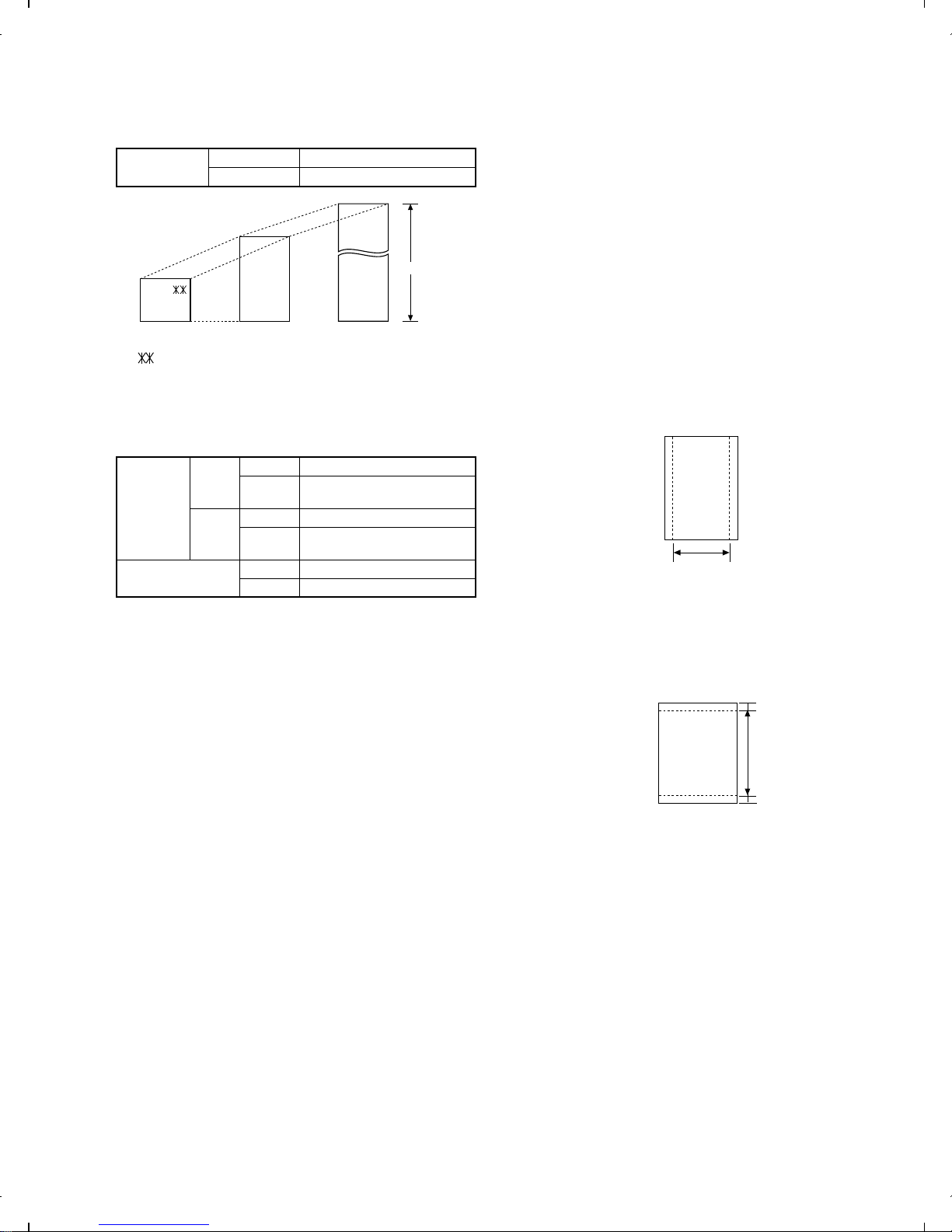
7. Use of Document Carrier Sheet
A document carrier sheet must be used for the following documents.
•Those with tears.
•Those smaller than size 148 mm (W) x 128 mm (L).
•Carbon-backed documents
NOTE: To transmit a carbon-backed document, insert a white sheet
of paper between the carbon back of the document and the
document carrier.
•Those containing an easily separable writing substance (e.g., trac-
ing paper written on with a soft, heavy lead pencil).
NOTES: •When using the document carrier, carefully read the in-
structions written on the back.
•If the document carrier is dirty, clean it with a soft, moist
cloth, and then dry it before using for transmission.
•Do not place more than one document in the carrier at a
time.
[4] Installation
1. Site selection
Take the following points into consideration when selecting a site for
this model.
ENVIRONMENT
•The machine must be installed on a level surface.
•Keep the machine away from air conditioners, heaters, direct sun-
light, and dust.
•Provide easy access to the front, back, and sides of the machine.
In particular, keep the area in front of the machine clear, or the
original document may jam as it comes out after scanning.
•The temperature should be between 5°and 35°C.
•The humidity should be between 30% and 85% (without conden-
sation).
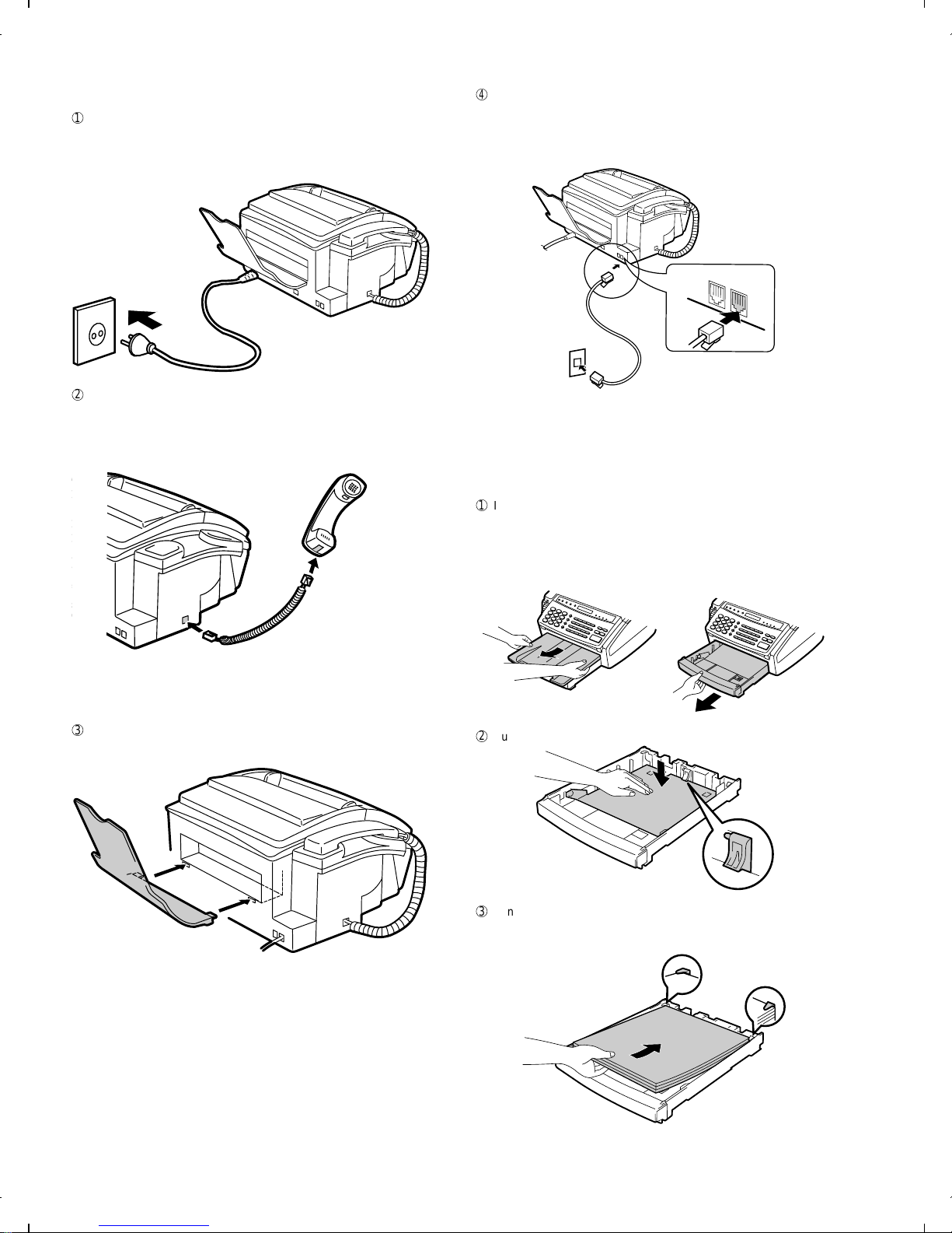
ELECTRICITY
230-240V, 50 Hz, grounded (2-prong) AC outlet is required.
Caution!
•Connection to a power source other than that specified will cause
damage to the equipment and is not covered under the warranty.
•If your area experiences a high incidence of lightning or power
surges, we recommend that you install a surge protector for the
power and telephone lines. Surge protectors can be purchased at
most telephone specialty stores.
If the machine is moved from a cold to a warm place...
If the machine is moved from a cold to a warm place, it is possible
that the reading glass may fog up, preventing proper scanning of
documents for transmission. To remove the fog, turn on the power
and wait approximately 2 hours before using the machine.
TELEPHONE JACK
A standard RJ11C telephone jack must be located near the machine.
This is the telephone jack commonly used in most homes and offices.
•Plugging the fax machine into a jack which is not an RJ11C jack
may result in damage to the machine or your telephone system. If
you do not know what kind of jack you have, or needed to have
one installed, contact the telephone company.
2. Installing the imaging film (FO-16CR)
1
Grasp the finger hold on the right side of the printing compartment
cover, and pull up to open the cover.
2
Push back the green levers on each side of the printing compart-
ment, and rotate the printing head frame up and to the rear.
•Caution! The printing head (the strip of metal on the under-
side of the frame) applies heat to the printing film. It
may be hot if a document has just been printed.
3
If you are replacing the imaging film, take the old film out of the
printing compartment and remove the three (3) green gears and
the green flange from the ends of the spools.
DO NOT DISCARD THE GREEN GEARS AND THE GREEN
FLANGE!
Direction of insertion
Make print straight
across paper
E.G.
Place the document
carrier in the document
feeder with the clear film
side down
FO-1850TH
1 – 4