E-2
Precautions
General
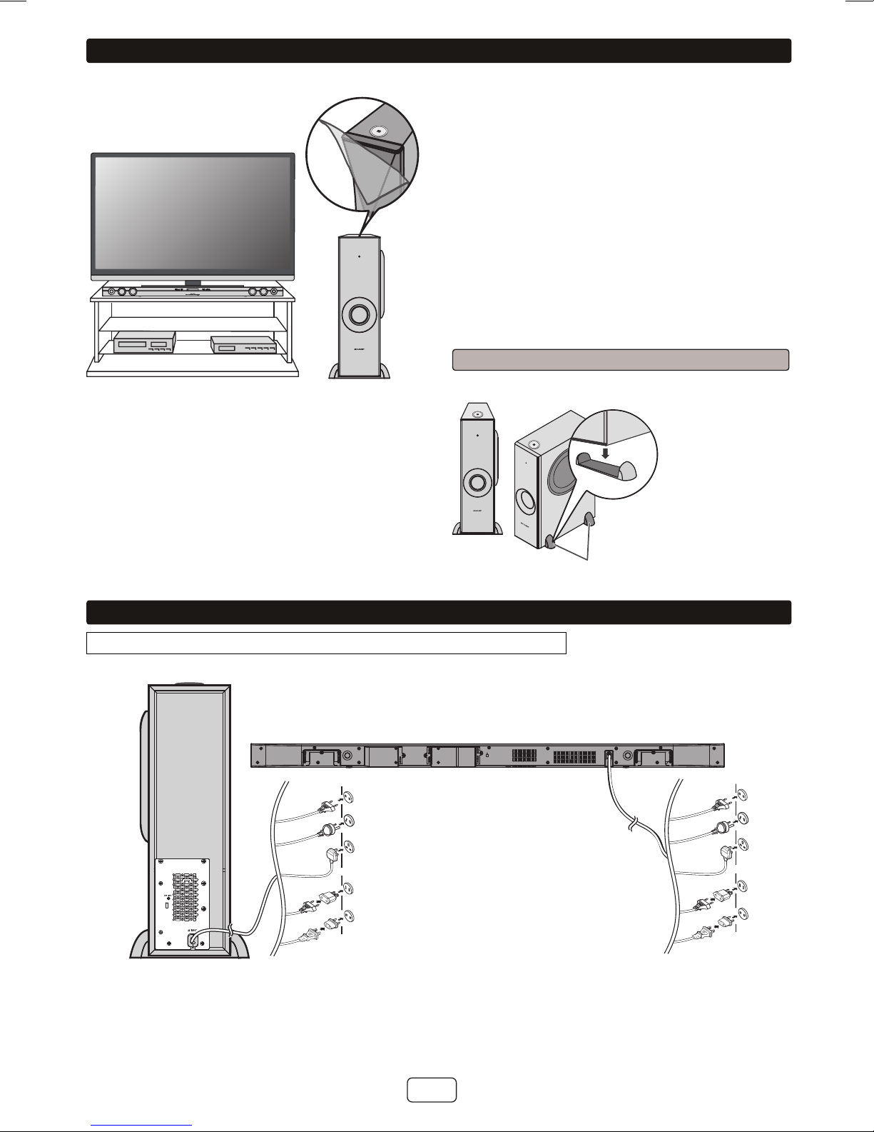
Keep your equipment at least 10 cm of free space
along the sides, top and back for proper ventilation.
10 cm
10 cm
10 cm
10 cm
10 cm
10 cm10 cm
Use the unit on a firm, level surface free from vibration.
Keep the unit away from direct sunlight, strong
magnetic fields, excessive dust, humidity and
electronic/electrical equipment (home computers,
facsimiles, etc.) which generate electrical noise.
Do not place anything on top of the unit.
Do not expose the unit to moisture, to temperatures
higher than 60°C (140°F) or to extremely low
temperatures.
If the unit does not work properly, unplug and plug it in
again. Than turn on the unit.
In case of an electrical storm, unplug the unit for
safety.
Hold the AC power plug by the head when removing it
from the wall socket, as pulling the lead can damage
internal wires.
The AC power plug is used as a disconnect device
and shall always remain readily operable.
Do not remove the outer cover, as this may result
in electric shock. Refer internal service to your
local SHARP service facility.
The ventilation should not be impeded by covering the
ventilation openings with items, such as newspapers,
tablecloths, curtains, etc.
No naked flame sources, such as lighted candles,
should be placed on the apparatus.
Attention should be drawn to the environmental
aspects of battery disposal.
This unit should only be used within the range of 5°C -
35°C (41°F - 95°F).
SHARP is not responsible for damage due to improper
use. Refer all servicing to a SHARP authorised
service centre.
Warnings:
The voltage used must be the same as that specified
on this unit. Using a higher voltage is dangerous and
may result in a fire or other type of accident causing
damage. SHARP will not be held responsible for any
damage resulting from such usage.
In case of repairing, please bring the entire system set
to the service centre.
Volume control
The sound level at a given volume setting depends on
speaker efficiency, location and various other factors.
It is advisable to avoid exposure to high volume levels,
which occurs whilst turning the unit on with the volume
control setting up high, or whilst continually listening at
high volumes.
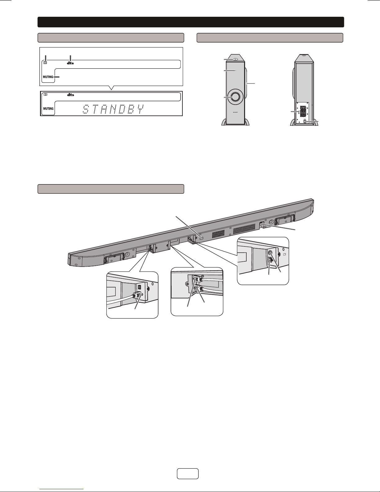
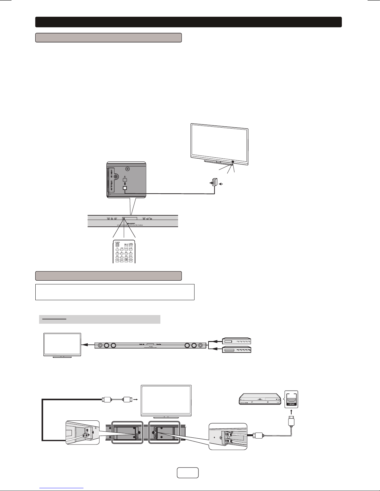
Controls and indicators
Sound Bar Front Panel
1
34 5 76 8 9
2
1. Left Channel Speakers
2. Right Channel Speakers
3. On/Standby Button
4. INPUT Button
5. Pairing Button
6. Remote Sensor
7. Sound Mode Button
8. Volume Down Button
9. Volume Up Button