Shure EXHIBIT 212 User manual

Case: 1:17-cv-03078 Document #: 901-3 Filed: 08/12/20 Page 580 of 609 PageID #:48596
Page 1 of 26
PGR2020-00079
Shure v. ClearOne
ClearOne Ex. 2169

Page 1
1
TABLE OF CONTENTS
INTRODUCTION ..................................................................................................3
CTG System Components............................................................................................................................ 3
Other Components that may be connected ................................................................................................ 3
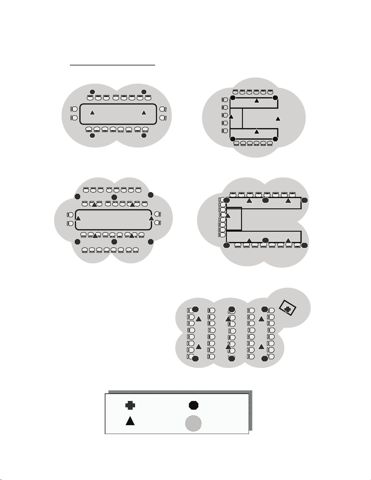
Typical Room Configurations ..................................................................................................................... 4
INSTALLATION AND WIRING OF CTG MICROPHONES AND SPEAKERS.....5
Tools Required for Installation ................................................................................................................... 5
CTG Microphones-General......................................................................................................................... 5
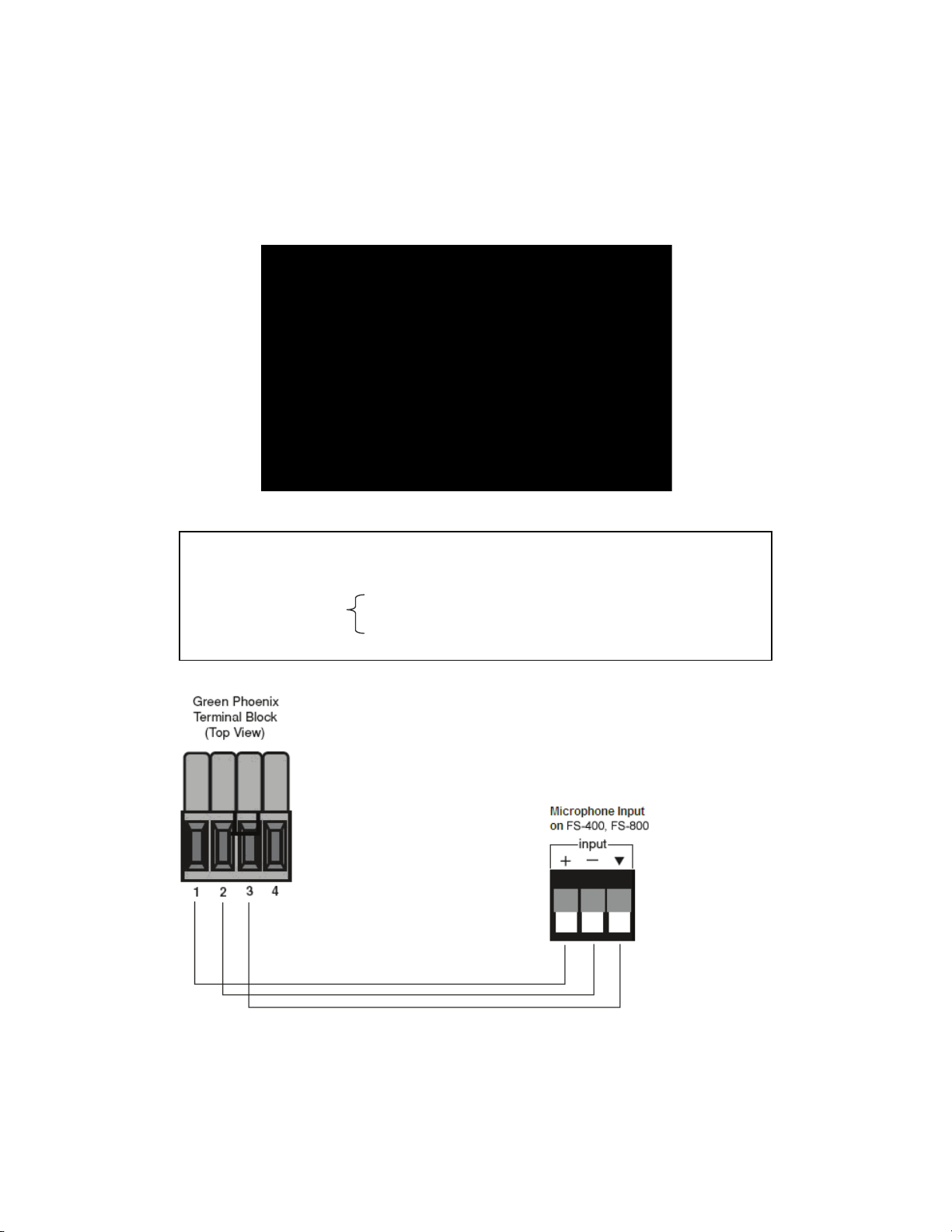
Connection Module Wiring Detail .............................................................................................................. 6
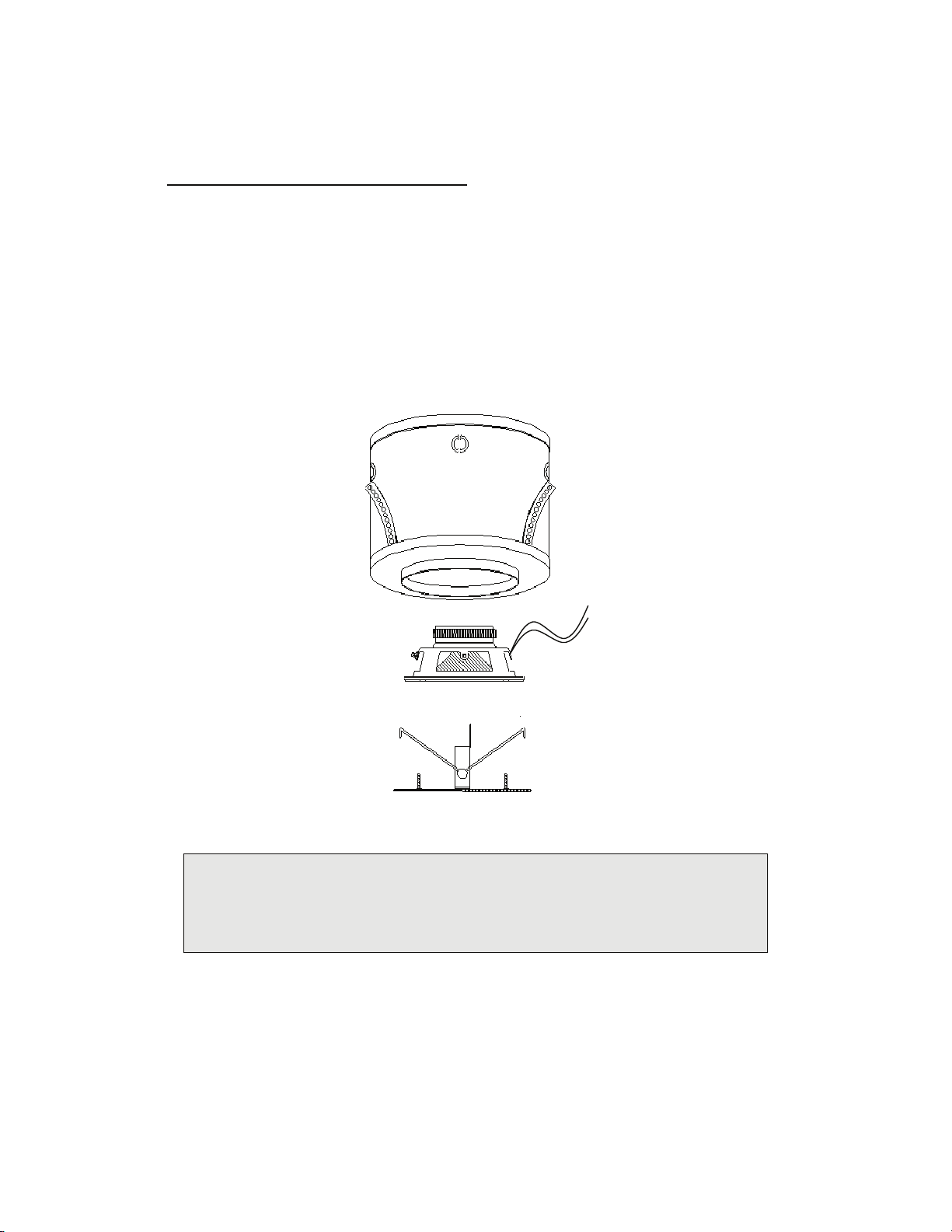
Ceiling Microphone (CM-01) Mounting Detail: ........................................................................................ 7
Table Implant Microphone (TM-02) Mounting Detail.............................................................................. 8
Table Top Microphone (TM-01) Mounting Detail: ...................................................................................8
Ceiling Speaker (SP-01) Mounting Detail .................................................................................................. 8
Ceiling Speaker (SP-01) Mounting Detail .................................................................................................. 9
FS-400 AND FS-800 BEAMFORMING TELECONFERENCE INTERFACES ...10
Overview ..................................................................................................................................................... 10
Panel Descriptions ...................................................................................................................................... 11
Connecting and Placing Audio Conference Calls .................................................................................... 13
Calibration for Audio Conferencing ........................................................................................................ 14
Integration to Video Conferencing ........................................................................................................... 14
Codec Compatibility................................................................................................................................ 14
Connecting the Codec.............................................................................................................................. 14
Calibration for Video Codec.................................................................................................................... 15
Recording a Conference............................................................................................................................. 16
Linking Multiple Mixers............................................................................................................................ 17
CTG SOFTWARE...............................................................................................18
Advanced Control Panel ............................................................................................................................ 19
Case: 1:17-cv-03078 Document #: 901-3 Filed: 08/12/20 Page 581 of 609 PageID #:48597
Page 2 of 26
PGR2020-00079
Shure v. ClearOne
ClearOne Ex. 2169

Page 2
2
Basic Control Panel .................................................................................................................................... 20
Adjusting Volume Settings ........................................................................................................................ 20
Push to Talk Feature .................................................................................................................................. 21
TROUBLESHOOTING GUIDE ...........................................................................22
COMPONENT SPECIFICATIONS .....................................................................23
CTG FS-400 and FS-800 Specifications.................................................................................................... 23
CTG Microphones: CM-01, TM-01, TM-02. ...........................................................................................24
SP-01 Ceiling Speaker Module.................................................................................................................. 24
RETURNS ..........................................................................................................24
WARRANTY………………………………………………..….INSIDE REAR COVER
Case: 1:17-cv-03078 Document #: 901-3 Filed: 08/12/20 Page 582 of 609 PageID #:48598
Page 3 of 26
PGR2020-00079
Shure v. ClearOne
ClearOne Ex. 2169

Page 3
3
Rev 11/21/2008
Introduction
This manual provides instructions for the wiring and mounting of CTG
microphones, speaker modules, and the connections and operation of the FS-
400/800 Beamforming Mixers.
CTG System Components
FS-400 or FS-800 Mixer and Teleconference Interface
CM-01 Ceiling Microphones
TM-01 Tabletop Microphones
TM-02 Table Implant Microphones
SP-01 Ceiling Speaker Modules
Telephone dial pad
Power adapter
USB cable
Mixer linking cable
Software CD
The Software includes Setup, Recording, and Phone Dialing utilities. Please refer to the
Help files for information on using the Setup and recording software. The Dialer is
intuitive and needs no Help file.
We suggest checking our website periodically for updates and additions to our software
library at http://www.ctgaudio.com
Other Components that may be connected
(Check with CTG for compatibility by manufacturer and model)
Group videoconferencing system
Ceiling, table, lapel, podium or handheld presentation microphone
Recording Device
Amplifier to drive room speakers
CTG is available to remotely assist with the design, installation and/or
troubleshooting of all CTG systems at no charge.Please contact technical support
with any questions or for assistance.
Conference Technology Group
3740 Kori Road
Jacksonville, FL 32257
904.880.5125 telephone
75.146.66.189 IP video
Case: 1:17-cv-03078 Document #: 901-3 Filed: 08/12/20 Page 583 of 609 PageID #:48599
Page 4 of 26
PGR2020-00079
Shure v. ClearOne
ClearOne Ex. 2169

Page 4
4
Typical Room Configurations
Drawings show microphone and speaker locations
U-shaped tables
30’x30’ coverage area
Large u-shaped tables
40’x30’ coverage area
Centered conference table
25’x15’ coverage area
Centered conference table with perimeter seating
45’x30’ coverage area
Training room with movable furniture
50’x30’ coverage area
Table Microphone
Ceiling Microphone
Ceiling Speaker
Microphone
Coverage area
Case: 1:17-cv-03078 Document #: 901-3 Filed: 08/12/20 Page 584 of 609 PageID #:48600
Page 5 of 26
PGR2020-00079
Shure v. ClearOne
ClearOne Ex. 2169

Page 5
5
Installation and wiring of CTG Microphones and Speakers
Tools Required for Installation
The following tools are recommended for the installation of the ceiling components and
setup:
½inch drill – for drilling through an acoustic tile, a perfect hole will be made for
the CM-01 ceiling microphone
Hand saw – the ceiling speaker enclosure requires a 6 3/8-inch hole
Wall snake – in most rooms, cables will need to run down through a wall and
terminate at the FS-400, FS-800
Wire nuts – for ceiling speakers
Wire Stripper
Small blade screw driver – often referred to in the industry as a “tweaker”
Ladder
CTG Microphones-General
CTG microphones are true 360° Omni directional. They are electret condenser boundary
microphones. The microphone itself should be flush mounted in a boundary of at least
12” in diameter. The element in the table top microphone (TM-01) is mounted in a base
designed to acoustically couple to the table surface and provide an adequate boundary.
CTG microphones connect to microphone Inputs.*
* Each microphone must connect directly to the FS-400/800 with a “homerun”
connection.
Recommended Microphone Cable
22 gauge single pair shielded (plenum rated) Belden® type 82761 or equivalent
CAUTION:
Phantom voltage supplied to CTG microphones can be 2 to 50 Volts DC. The FS-400/800
microphone inputs provide 24 volts DC
To avoid crosstalk, it is preferred microphone and speaker cable NOT be bundled or run
together in the same conduit over long distances
Case: 1:17-cv-03078 Document #: 901-3 Filed: 08/12/20 Page 585 of 609 PageID #:48601
Page 6 of 26
PGR2020-00079
Shure v. ClearOne
ClearOne Ex. 2169

Page 6
6
Connection Module Wiring Detail
A connection module (MCM-101) is supplied with each microphone
On the MCM-101 is a four position Phoenix Terminal Block.
Phoenix Terminal Block
Connection Module
PHOENIX TERMINAL BLOCK CONNECTIONS:
Terminal 1….Positive
Terminal 2….Negative
Terminal 3….Shield
Terminal 4….To housing
Note:
A ground jumper between terminals 3 and 4 should be removed if the
ceiling tile is foil backed or if any part of the microphone housing
comes in contact with building ground.
Case: 1:17-cv-03078 Document #: 901-3 Filed: 08/12/20 Page 586 of 609 PageID #:48602
Page 7 of 26
PGR2020-00079
Shure v. ClearOne
ClearOne Ex. 2169

Page 7
7
Ceiling Microphone (CM-01) Mounting Detail
(Note, ceiling microphones should not be mounted in ceilings higher than 10 feet without consulting CTG
support)
STEP 1
Wire Phoenix Terminal
Block to end of cable run
from the FS-400/800
microphone input and
plug into connection
module.
STEP 2
Drill ½” hole in the tile at
desired location. Push
microphone barrel, with
attached 18” cable and
mini XLR connector up
through ½” hole in tile
until lip stops against tile.
Secure on top of tile with
friction clip.
STEP 3
Plug mini XLR connector at
end of 18” cable into male
jack on connection module.
Rest connection module on
top of tile.
Case: 1:17-cv-03078 Document #: 901-3 Filed: 08/12/20 Page 587 of 609 PageID #:48603
Page 8 of 26
PGR2020-00079
Shure v. ClearOne
ClearOne Ex. 2169

Page 8
8
Table Implant Microphone (TM-02) Mounting Detail
Table Top Microphone (TM-01) Mounting Detail:
Ceiling Speaker (SP-01) Mounting Detail
Step 1: Drill ½” hole into the table
Push microphone barrel, with attached 18”cable and mini XLR through the
table from surface until lip stops. Secure from underneath with friction clip.
Step 2: Position connection module underneath the table within reach of the 18”
microphone cable. Remove protective paper from the foam tape and press the
bottom to table. Secure with screws provided and plug in the mini XLR from
microphone cable.
Step 3: Wire Phoenix Terminal Block to end of cable run from FS-400/800 microphone
input and plug into connection module.
Step 1: Position connection module to desired location underneath table. Remove
paper from the foam tape and press the bottom to table. Secure with screws.
Step 2: Plug mini XLR from table microphone cable into module and locate microphone on
the table.
Step 3: Wire Phoenix Terminal Block to end of cable run from FS-400/800 microphone
input and plug into connection module.
Case: 1:17-cv-03078 Document #: 901-3 Filed: 08/12/20 Page 588 of 609 PageID #:48604
Page 9 of 26
PGR2020-00079
Shure v. ClearOne
ClearOne Ex. 2169

Page 9
9
The speaker enclosures supplied will require a 6 3/8-inch hole in the ceiling material.
Ceiling Speaker (SP-01) Mounting Detail
The speaker grills are supplied with the speakers already mounted and attached to the
enclosures with torsion springs inserted into clips inside the enclosure. To remove the
grille simply pull it away from the enclosure and compress the springs to detach.
To simplify installation CTG attaches a twelve-inch wire to each speaker terminal so that
it may be connected with wire nuts. The red wire is positive.
(Note: Blind mounts are available from CTG for dry wall ceilings or ceilings with
inadequate space above. Tile bridges are also available as an option.)
Although the FS-400/800 mixers do not contain a speaker amplifier, it is vital that return
audio from an external video codec be routed through the mixers before being connected
to a speaker amplifier. This allows the return audio to be sampled to enable echo
cancellation. To facilitate this there are SPEAKER IN and SPEAKER OUT
connections on the rear panel of the mixers.
Each speaker has a
direct “homerun”
connection to the
speaker amplifier
Recommended speaker cable:
18 gauge twisted pair (plenum rated) Belden type 82740 or
equivalent
Case: 1:17-cv-03078 Document #: 901-3 Filed: 08/12/20 Page 589 of 609 PageID #:48605
Page 10 of 26
PGR2020-00079
Shure v. ClearOne
ClearOne Ex. 2169

Page 10
10
FS-400 and FS-800 Beamforming Teleconference Interfaces
Overview
The CTG FS-400 and FS-800 Beamforming Mixers are an advanced solution for group
audio and video teleconferencing, intra-room presentations, and meetings with recording
capacity. They differ only in the number of microphone inputs (4 or 8), and both include
a telephone interface to connect directly to the Public Service Telephone Network
(PSTN). They can also connect at Line Level to any Video codec with a suitable Line
Level input connection. The FS-400 and FS-800 may be daisy chained to allow a nearly
infinite number of microphones. Any mixer in the chain may be the master. The mixers
provide advanced Echo Cancellation, Noise Reduction, and De-Reverberation to reduce
the room reflections that can seriously degrade speech intelligibility. Simple software is
provided to set audio levels for the microphone mixer and the telephone interface.
Recording software is also included. A dial pad is included to dial, connect and
disconnect phone calls.
Both of the mixers take advantage of the increased computational power of the latest
digital processors to provide enhancements not previously available. Every attached
microphone is sampled 16,000 times per second and the audio picked up by each is
analyzed and compared in arrival time. Audio from any microphone that enhances
intelligibility of a person speaking is combined, while audio that would degrade
intelligibility is discarded. The system constantly adjusts to changes and effectively
follows a moving speaker.
Noise Suppression- Noise suppressor acts on long term noise (HVAC noise, fans, and
lighting hum.
De-Reverberation- All sounds in a room are reflected from room surfaces. A de-
reverberation algorithm determines reflections by comparing the time difference with the
original sound and reduces annoying room echoes. As a result rooms that have marginal
acoustic characteristics for good teleconferencing are made usable.
Case: 1:17-cv-03078 Document #: 901-3 Filed: 08/12/20 Page 590 of 609 PageID #:48606
Page 11 of 26
PGR2020-00079
Shure v. ClearOne
ClearOne Ex. 2169

Page 11
11
Panel Descriptions
The FS-400/800 powers the CTG microphones and can be linked to
support an unlimited number of microphones. The PSTN phone line
connection allows for stand alone audio conferencing and the Interfaces
are easily integrated to video conferencing codec’s.
Front panel of FS-400 or FS-800
1. Power on/off Switch with LED indicator
2. USB mini B: Used for PC Communication, both audio and setup
3. Dialer: Input for dial pad to dial, connect and disconnect calls
4. Phone Line: Input (standard RJ11) to connect phone line from wall plate
Case: 1:17-cv-03078 Document #: 901-3 Filed: 08/12/20 Page 591 of 609 PageID #:48607
Page 12 of 26
PGR2020-00079
Shure v. ClearOne
ClearOne Ex. 2169

Page 12
12
Back panel of FS- 400
5. Microphone inputs (1-4): CTG ceiling microphones, table microphones, or
implant microphones are connected here.
6. Speaker In (mandatory): This is the return audio from the video codec
7. Output: This output is connected to a line level input of the video codec
8. Speaker Out: This will be connected to the speaker amplifier.
9. Link Up: This is an expansion port which allows multiple units to be linked
together and function as one system for large rooms.
10. Link Down: This is an expansion port which allows multiple units to be linked
together and function as one system for large rooms.
11. Power Connector: USB: Power supply through USB mini B @ 5 V DC
automatically adjusts to 110 to 240 volt mains.
Back Panel FS- 800
12. Microphone inputs (1- 4): CTG ceiling microphones, table microphones, or
implant microphones are connected here
13. Speaker In (mandatory): This is the return audio from the video codec
14. Mixer Output: This output is connected to a line level input of the video codec.
15. Speaker Out: This will be connected to the speaker amplifier.
16. Link Up: This is an expansion port which allows multiple units to be linked
together and function
17. Microphone inputs (5-8): CTG ceiling microphones, table microphones, or
implant microphones are connected here.
18. Link Down: This is an expansion port which allows multiple units to be linked
together and function as one system for large rooms.
19. Power Connector USB provided power supply through USB mini B at
5 VDC automatically adjusts to 110 to 240 volt mains.
Case: 1:17-cv-03078 Document #: 901-3 Filed: 08/12/20 Page 592 of 609 PageID #:48608
Page 13 of 26
PGR2020-00079
Shure v. ClearOne
ClearOne Ex. 2169

Page 13
13
Connecting and Placing Audio Conference Calls
For audio teleconferencing over standard analog PSTN phone lines there are two
options. First connect the FS-400/800 to the standard RJ-11 telephone wall jack from the
similar jack marked Phone Line on the mixers front panel.
1. A software dialer, similar to the hardware dial pad but with additional capabilities,
such as Flash, Mute, Volume, and Number Recall is included on the supplied software
CD, and may be used instead of the hardware dialer shown below through the USB Data
port.
2. Or attach the included hardware telephone dial pad to the narrower jack marked
Dialer. To place a call press the button at the top of the dial pad showing a telephone
handset, and dial when the dial tone is heard, to hang up after the conference, press the
same button again. (see Illus. A) Telephone volume level can be adjusted with the
CTG Setup Software (Page 18). There are two additional buttons at the top of the dial
pad that can be pressed to conveniently redial the last dialed phone number.
(Illus. A)
Case: 1:17-cv-03078 Document #: 901-3 Filed: 08/12/20 Page 593 of 609 PageID #:48609
Page 14 of 26
PGR2020-00079
Shure v. ClearOne
ClearOne Ex. 2169

Page 14
14
Calibration for Audio Conferencing
It is important to maintain “standard transmission levels” with handsets, speakerphones
and conference phones. The standards that reference “Send Loudness Ratings” (SLR) are
described in the ITU’s G. 111 standard and also referenced in the P. 340 standard.
The goal is to maintain a dynamic range >20db as described in the videoconferencing
calibration section. The speech level should average +6db to ensure a comfortable level
at the far end.
In General, the audio level of people speaking in the distant rooms should be about the
same as a person speaking in the same room with you.
Integration to Video Conferencing
Codec Compatibility
The FS-400 and the FS-800 are compatible with almost all video codec’s.
Connecting the Codec
The FS-400/800 Output should be connected at line level to a video codec. CTG will
provide the appropriate connecting cable for the particular codec model if known. The
following illustration shows the connection between video codec and the microphone
mixer. For specific illustrations and instructions to connect to commonly used codecs
refer to the support section of www.ctgaudio.com or call CTG support at (904) 880-5125
Codec (Rear Panel): NOTE: This Illustration is a simulated codec panel and does not
represent any particular brand.
Case: 1:17-cv-03078 Document #: 901-3 Filed: 08/12/20 Page 594 of 609 PageID #:48610
Page 15 of 26
PGR2020-00079
Shure v. ClearOne
ClearOne Ex. 2169

Page 15
15
Calibration for Video Codec
It is important to maintain “standard transmission levels” to be compatible with other systems.
The following illustration details the targeted send level.
Some codecs have an audio meter that displays the transmission level.
Ideally the output level of the mixer should be adjusted so voices peak between +5 to +10 dB.
CTG technical support can assist in determining the proper send level over a video call.
During calibration, the volume control indicator of the video codec should be set at about mid-
range. Typically the video codec will display an on screen graphic that will indicate the incoming
audio level when a volume key is pressed.
-20 -15 -10 0 +5 +10 +15
Ideal noise floor – noise should not
be detected at the distant end if the
ambient noise floor is under -12dB
Ideal speech level – adjust send
level so average speech peaks at
+8 to +10
Dynamic range goal = >20dB
FS-400/800 provides
exceptional signal to
noise ratio
Case: 1:17-cv-03078 Document #: 901-3 Filed: 08/12/20 Page 595 of 609 PageID #:48611
Page 16 of 26
PGR2020-00079
Shure v. ClearOne
ClearOne Ex. 2169

Page 16
16
Recording a Conference
Audio recordings can be made of a conference by connecting a computer to the front
panel USB Jack on the FS-400/800 and recording to a computer hard drive. This may
also be used to record meetings within a room. When another recording device is used to
record within a room (no teleconferencing) the output jack on the back panel can be
connected at line level to a recorder. (See Illus. B)
Easy to use CTG Windows recording software is included. Instructions for recording can
be found in the recording software utility help file.
(Illus. B)
(Note: when using the FS-400/800 output for recording within a room, a codec or other line level
device may not be connected)
Case: 1:17-cv-03078 Document #: 901-3 Filed: 08/12/20 Page 596 of 609 PageID #:48612
Page 17 of 26
PGR2020-00079
Shure v. ClearOne
ClearOne Ex. 2169

Page 17
17
Linking Multiple Mixers
A short linking cable is provided with every mixer. Any number of FS-400 and FS-800
mixers can be linked to support any number of microphones required. The link
connectors on each end of the cable are different to prevent being plugged into the wrong
LINK jack. (see illus E) Any mixer in the chain can act as a master or slave, Any
software level change made to any mixer will be applied to all the mixers in the chain.
(Illus. E)
Case: 1:17-cv-03078 Document #: 901-3 Filed: 08/12/20 Page 597 of 609 PageID #:48613
Page 18 of 26
PGR2020-00079
Shure v. ClearOne
ClearOne Ex. 2169

Page 18
18
CTG Software
To load and use setup software, connect USB cable to front panel data port,(see illus. D)
(Illus. D)
The CTG Audio Setup Utility is designed to help you control the audio levels coming in
and going out of your CTG product. This utility will:
1) Identify the CTG device you are using and indicate whether it’s connected (or not
connected).
2) Set the audio levels to a comfortable default value. Once you modify the levels the unit
will save and restore your preferred levels anytime you connect a unit or open the audio
utility (you can choose not to save your settings and to go back to the default values).
3) The utility will allow you to control the level of signal going to and coming back from
your telephone. It will also allow you to control the level and balance of the bridge (the
connection between your telephone counterpart and VoIP counterpart in PSTN versions)
This utility is not necessary in order to use your CTG system. Some audio levels (VoIP)
can be controlled through your Windows mixers while others that are not controlled by
Windows (telephone and bridge) are set to a comfortable default level. However, this
utility adds another level of control that some users prefer to have.
An important feature of the utility is the ability to disable / enable the bridge connection.
This is intended to prevent your telephone counterpart from hearing unwanted sounds
coming out of your computer.
The software must be installed to a laptop or desktop computer running Microsoft
Windows 98 or newer, and connected to the FS-400 or FS-800 mixer with the provided
USB cable to the front Data Port on the mixer. The indicator will turn from Red to Green
and indicate the device is connected. If you already have an older version of the CTG
Case: 1:17-cv-03078 Document #: 901-3 Filed: 08/12/20 Page 598 of 609 PageID #:48614
Page 19 of 26
PGR2020-00079
Shure v. ClearOne
ClearOne Ex. 2169

Page 19
19
Audio Setup you will need to uninstall it first. Please go to “Start”-> “Control Panel” -
> “Add or Remove Programs”, look for “CTG Audio Setup” and choose “Remove”.
Locate the installation file downloaded to your PC or use the Provided CD. Run the
installation wizard by double-clicking on the file icon and choosing “Run”. Follow the
instructions on the installation wizard, and click finish when done. A shortcut for the
CTG Audio Setup Utility will automatically be placed on your Windows' desktop screen
after installation. Once installed, you can double-click on the shortcut to launch the
utility.
To uninstall this software use the Windows Add / Remove utility. To do so click on
“Start” -> “Control Panel” -> “Add or Remove Programs”. After clicking “Add or
Remove Programs” you should scroll down the list of software applications installed on
your PC until you find “CTG Audio Setup”. Once found, click on the “Remove” button
next to it and then click “Yes”.
Advanced Control Panel
The advanced control panel allows you to control:
Speaker:
- Level of signal coming from the PC (VoIP communication)
- Level of signal coming from the Phone (or VCA)
- Master volume controlling directly the signal broadcasted on the
device’s loudspeaker
Transmit:
- Level of signal sent to the PC (VoIP communication)
- Level of signal sent to your Phone (or VCA)
- Master volume controlling directly the level of your internal
microphone’s signal
Case: 1:17-cv-03078 Document #: 901-3 Filed: 08/12/20 Page 599 of 609 PageID #:48615
Page 20 of 26
PGR2020-00079
Shure v. ClearOne
ClearOne Ex. 2169
Table of contents
Other Shure Microphone System manuals

Shure
Shure UHF Wireless System Owner's manual

Shure
Shure UHF-R Wireless User manual

Shure
Shure BLX4R User manual

Shure
Shure AMS4000 User guide

Shure
Shure ULX-D User manual

Shure
Shure Performance Gear User manual

Shure
Shure THE TWIN PRO 27C8642 User manual

Shure
Shure ULX-D User manual

Shure
Shure PGXD Series User manual

Shure
Shure BLX24R/SM58-H10 User manual

Shure
Shure PSM1000 User manual

Shure
Shure A412B User manual

Shure
Shure GLX-D User manual

Shure
Shure Microflex MX400 Series User manual

Shure
Shure M44C User manual

Shure
Shure A412B User manual

Shure
Shure SLX Wireless System User manual

Shure
Shure BLX Wireless System User manual

Shure
Shure T series User manual

Shure
Shure BLX Wireless System User manual