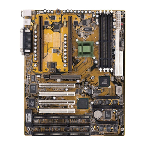
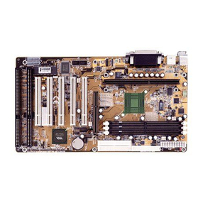
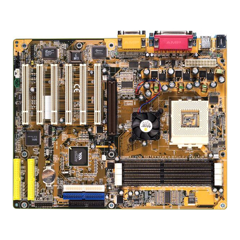
Shuttle HOT-579 User manual

HOT-579
Pentium™processor
Based PCIMAINBOARD
User's Manual

1
NOTICE
Copyright 1997.
AllRightReserved
Manual Ver 1.1
Allinformation, documentation, andspecifications contained inthis manual aresubject to changewithout prior
notificationbythemanufacturer.
The author assumes no responsibility for any errors or omissions which may appear in this document nor does it make a
commitment to update the information contained herein.
TRADEMARKS
All the brands and product names referred to in this manual are trademarks or registered trademarks of their respective
holders.
FCC Notice:
This equipment has been tested and found to comply with the limits for a Class B digital device, pursuant to Part 15 of FCC
Rules. These limits are designed to provide reasonable protection against harmful interference in a residential installation.
This equipment generates, uses and can radiate radio frequency energy. If not installed and used properly, in strict accordance
with the manufacturer's instructions, may cause harmful interference to radio communications. However, there is no guarantee
that interference will not occur in a particular installation. If this equipment does cause interference to radio or television
reception, which can be determined by turning the equipment off and on, the user is encouraged to try to correct the interfer-
ence by one or more of the following measures :
Reorient or relocate the receiving antenna.
Increase the separation between the equipment and receiver.
Connect the equipment into an outlet on a circuit different from that to which the receiver is connected.
Consult the dealer or an experienced radio/television technician for help and for additional suggestions.
The user may find the following booklet prepared by the Federal Communications Commission helpful "How to Identify and
Resolve Radio-TV Interference Problems." This booklet is available from the U.S. Government Printing Office. Washington,
DC 20402, Stock 004-000-00345-4
FCCWarning
The user is cautioned that changes or modifications not expressly approved by the manufacturer could void the users authority
to operate this equipment.
Note: In order for an installation of this product to maintain compliancewith the limits for a Class B device, shielded cables
and power cord must be used.
CE Notice:
Following standards were applied to this product, in order to achieve compliance with the electromagnetic compatibility :
- Immunity in accordance with EN 50082-1: 1992
- Emissions in accordance with EN 55022: 1987 Class B.

2
T
T
PREFACE ........................................................................................................................3
CHAPTER 1 FEATURES ......................................................................................................4
Accessories of HOT-579 .......................................................................................................................... 6
CHAPTER 2HARDWARE CONFIGURATION.............................................................................7
Jumper Setting........................................................................................................................................... 7
CPUClock Configurations - JP4 ~ JP6 and JP11 ~ JP14........................................................................ 8
SystemClock and CPUMultiplier onHOT-579 ..................................................................................... 9
CPUVoltage Configuration -JP33 ........................................................................................................ 10
Flash EEPROM Vpp - JP17................................................................................................................... 11
ClearCMOS -JP19................................................................................................................................. 11
PowerSupply Type Select - JP31........................................................................................................... 11
Connectors& Sockets............................................................................................................................. 12
CHAPTER 3MEMORY CONFIGURATION ..............................................................................14
CHAPTER 4 FLASH UTILITY .............................................................................................16
CHAPTER 5 BIOS SETUP ...............................................................................................18
MainMenu .............................................................................................................................................. 19
StandardCMOS Setup............................................................................................................................ 21
BIOS Features Setup............................................................................................................................... 23
Chipset Features Setup............................................................................................................................ 25
PowerManagement Setup ...................................................................................................................... 27
PCIConfiguration Setup......................................................................................................................... 29
Integrated Peripherals ............................................................................................................................. 31
PasswordSetting ..................................................................................................................................... 33
TABLE OF CONTENTS

3
P
P
HOT-579mainboardis a highlyintegratedIBM PC/AT compatible systemboard. The
designwill accept AMD K5, K6, Intel Pentium P54C, Pentium MMX, IDT-C6 and Cyrix/
IBM6x86, 6x86L, 6x86MX processors and also featureshigh-performance pipelinedburst
secondarycache memory support with size of 1024KB or 512KB. The memory subsystem
isdesigned to support up to 512 MB of EDO RAM, Standard FastPage DRAM and SDRAM
instandard 72-pin SIMM socket and 168-pin 3.3V DIMMsocket.
HOT-579provides a new level of I/O integration. VIA580VPX chipset provides increased
integrationandimprovedperformance over other chipsetdesigns.
TheVIA580VPX chipsetprovides anintegrated BusMastering IDEcontroller withtwo high
performanceUltra 33DMA IDE interfaces for up to four IDE devices.
TheonboardI/Ocontrollerprovides the standard PCI/Ofunctions:floppyinterface, two
FIFOserial ports,an IrDAdevice portand aSPP/EPP/ECP capableparallel port.
Upto fourPCI localbus slots provide a high bandwidth data path for data-movement
intensivefunctions suchas graphics,and up to three ISA slots complete the I/O function.
TheHOT-579 providesthe foundation for cost effective, high performance, highly expand-
ableplatforms, which deliverthelatest in Pentiumprocessor and I/Ostandard.
PREFACE

4
FEATURES
1
1
TheHOT-579 Mainboard is carefullydesigned for thedemanding PC userwhowants high performance
andmanyintelligentfeatures in a compactpackage:
Chipset:
FeaturesVIA580VPXChipset with I/Osubsystems.
CPUSupport:
AMD K6 166~266 MHz, K5 PR75~PR166,
IntelPentium 75~200MHz, Pentium MMX 166~233 MHz,
Cyrix/IBM6x86 P120+~P166+,6x86L P166+,6x86MX PR166~PR266,
IDT-C6150~200MHz.
SecondaryCache:
Onboard1024KB or512KB PipelinedBurst Cache.
VersatileMemorySupports:
Equippedwith fourSIMM sockets to support (4, 8,16, 32, 64 and128MB) 72-pin EDO or
FPmemory modulesand twoDIMM sockets to (8, 16, 32, 64 or 128MB) 168-pin
SDRAMmemory modulesup to256 MB.
PCIandISA ExpansionSlots:
Providesfour 32-bit PCI slotsand three 16-bit ISAslots.
OnboardI/OChip:
Providesone Floppyport; oneoptional PS/2mouse connector; twohigh-speed UART
compatibleserial ports andone parallel portwith ECP andEPP capabilities. Serial Port 2
canalso bedirected fromCOM2 tothe InfraredModule forwireless connections.
OnboardPCI Bus MasterIDE Controller:
TwoUltra DMA/33 Bus Master IDEPorts supportsfour IDE devices up to33 MB/sec
IDEtransfers and supports Enhanced PIO Modes 3 and 4and BusMaster IDE DMA
Mode 2 devices.
Onboard12-pin AT and20-pin ATXPower Supply:
ProvidesAT and ATXpower connector onboard.
ATXpower supports soft-on/off function.

5
SystemBIOS:
ProvideslicensedAwardV4.51PG BIOS on FlashEEPROM.
SupportsGreenPC, DMI andBundledwith Symbios Login(NCR) SDCMV4.0 SCSI
BIOS.
ACPI:
SupportACPI(AdvancedConfigurationandPowerInterface) function. ACPI provide
moreEnergy SavingFeatures for the future operating system supporting OS Direct
PowerManagement (OSPM) functionality.
BoardSize:
3/4baby AT compact size 220mm x 235mm.

6
ACCESSORIESOF HOT-579

7
2
2
Jumper Setting
Jumperpin headers show on right side are
usedtoconfigure system clock,CPU
multiplierandCPU voltages.
SystemClock- JP11,JP12 andJP13
JP11,JP12 andJP13 are3-pins header
jumperwhich isused toadjust System
Clock from 50MHz to 83 MHz.
CPUMultiplier -JP4, JP5and JP6
JP4,JP5 and JP6 are2-pins header jumper
hichis used to adjust CPU core multiplier
from 1.5X to 5.5X.
CPUVoltages-JP33
JP33is used to adjust onboard voltages output from Switching type regulatorsto CPU by
insertingor removing mini jumper from pin headers.
Thosehardware settings are made through the useof jumpercaps to connect jumper pins on
the main board. The jumpers will be show graphically such as to connect pins 3&4 and
5&6, and to connect pins 1&2 and 3&4 for six pin jumpers.
Jumpers will be show graphically such as to connect pins 2&4 and to connect
pins3&4 for four pin jumpers.
Jumpers with two pins will be shown as for Short (On) and for Open (Off).
Toconnect the pins, simply place a plasticjumper cap over the two pins as diagramed.
HARDWARECONFIGURATION

8
CPU Clock Configuration - JP4 ~ JP6 and JP11 ~ JP13
ProcessorSpeedSystem
Clock MultiplierVcore/Vio
IntelPentium
P55CMMX
233 MHz66 MHz3.5x2.8V/3.3V
200 MHz66 MHz3x2.8V/3.3V
166 MHz66 MHz2.5x2.8V/3.3V
IntelPentium
P54C
200 MHz66 MHz3x3.3V
166 MHz66 MHz2.5x3.3V
150 MHz60 MHz2.5x3.3V
133 MHz66 MHz2x3.3V
120 MHz60 MHz2x3.3V
100 MHz66 MHz1.5x3.3V
90 MHz60 MHz1.5x3.3V
75 MHz50 MHz1.5x3.3V
AMD-K6
266 MHz66 MHz4x2.2V/3.3V
233 MHz66 MHz3.5x3.2V/3.3V
(2.2V/3.3V)
200 MHz66 MHz3x2.9V/3.3V
166 MHz66 MHz2.5x2.9V/3.3V
AMD-K5
PR166 66 MHz1.75 x3.52V
PR133 66 MHz1.5x3.52V
PR120 60 MHz1.5x3.52V
PR100 66 MHz1.5x3.52V
PR90 60 MHz1.5x3.52V
PR75 50 MHz1.5x3.52V
Cyrix/IBM
6x86MX
PR266 66 MHz3.5x2.9V/3.3V
PR233 66 MHz3x2.9V/3.3V
PR200 66 MHz2.5x2.9V/3.3V
PR166 60 MHz2.5x2.9V/3.3V
Cyrix/IBM
6x86L P166+66 MHz2x2.8V/3.3V
P150+60 MHz2x2.8V/3.3V
Cyrix/IBM
6x86
P166+66 MHz2x3.52V
P150+60 MHz2x3.52V
P133+55 MHz2x3.52V
P120+50 MHz2x3.52V
IDT-C6
150MHz60 MHz2.5x3.52V
180MHz60 MHz3x3.52V
200MHz66 MHz3x3.52V
Table 2-1

9
SystemClock and CPUMultiplier on HOT-579
Forwhom like to set up system manually, listed tables show all theSystem Clock and CPU
Multiplierthat HOT-579 can offer.
Table2-2 showsthe System Clock from 50 MHz to 83 MHz.
Table2-3 showsCPU Multiplier from 1.5X to 5.5X.
Note:Since PCI clockis halfof systemclock, 75MHzand 83MHzsystemclocks may
causePCIclockbeyond PCIspecification.
System
Clock
JP11
JP12
JP13 PCIClock
50 MHzJP11:2-3On
JP12:2-3On
JP13:2-3On25 MHz
55 MHzJP11:2-3On
JP12:1-2On
JP13:2-3On27.5MHz
60 MHzJP11:1-2On
JP12:2-3On
JP13:2-3On30 MHz
66 MHzJP11:2-3On
JP12:2-3On
JP13:1-2On33 MHz
75 MHzJP11:1-2On
JP12:1-2On
JP13:2-3On37.5MHz
83 MHzJP11:2-3On
JP12:1-2On
JP13:1-2On41.5MHz
MultiplierJP4
JP5
JP6MultiplierJP4
JP5
JP6
1.5 x JP4:Off
JP5:Off
JP6:Off 4 x JP4:On
JP5:Off
JP6:On
2 x JP4:Off
JP5:Off
JP6:On4.5 x JP4:On
JP5:On
JP6:On
2.5 x JP4:Off
JP5:On
JP6:On5 x JP4:On
JP5:On
JP6:Off
3 x JP4:Off
JP5:On
JP6:Off 5.5 x JP4:On
JP5:Off
JP6:Off
3.5 x JP4:Off
JP5:Off
JP6:Off
Table 2-2
Table 2-3

10
CPU Voltage Configuration - JP33
Voltage JP33 Voltage JP33 Voltage JP33
Auto-setting
3.1 V 2.5 V
3.0 V 2.4 V
3.52 V 2.9 V 2.3 V
3.4 V 2.8 V 2.2 V
3.3 V 2.7 V 2.1 V
3.2 V 2.6 V
Table 2-4

11
FlashEEPROM Vpp -JP17
ClearCMOS - JP19
PowerSupply Type Select
HOT-579mainboard supports two types of Flash EEPROM:5 volt and 12 volt. By setting up
jumperJP17, the main board can use both 5V or 12V flash EEPROMwith new system BIOS
filesas they come available.
JP17 Pin2-3 Close for 12V Flash EEPROM
JP17 Pin 1-2 Close for 5V Flash EEPROM
HOT-579mainboard supports jumper JP19for discharging mainboard’sCMOS memory.
Thisjumper canclear the CMOS data stored in the sub-system chip. To clear the CMOS
datapleasefollowlistedsteps:
1) Turn off the PC,
2)Remove the jumper cap from JP19 pin 1-2,
3)Insert the jumper cap to JP19 pin 2-3 for a brief while,
4)Remove the jumper cap from JP19 pin 2-3,
5)Reinsert thejumper cap to JP19 pin 1-2,
6) Turn on the PC.
HOT-579provide bothAT andATX power connector on-board, AT and ATX power supply
areavailable on HOT-579. Jumper JP31 is used to set whattype of power supply is pluged to
the main board.
Power
SupplyTypeOutline JP31
12-Pin
AT Type
20-Pin
ATXType
Table 2-5

12
Connectors& Sockets
ITEMFUNCTIONITEMFUNCTION
SIM1,2,3,4On-boardSIMMsocketsUSB1UniversalSerialBus(USB)Connectors
DIMM1,2On-board3.3VDIMM socketsIRInfra-Red Connectors
PCI1,2,3,4On-boardPCISlotsHDDLEDOn-boardEnhanced IDER/WLEDConnector
SL1,2,3On-boardISA SlotsRESETHardwareResetSwitchConnector
IDE1On-boardPCIPrimaryIDEConnectorKEYLOCKPowerLEDand Keylock Connector
IDE2On-boardPCISecondaryIDEConnectorSPEAKERPCSpeakerConnector
FDC On-boardFloppyControllerConnectorCNA1ATXPowerSupplyConnector
PRN On-boardParallelPortConnectorCN9ATPowerSupplyConnector
COM1On-boardSerialPort-1ConnectorPWRONMomentaryTypeATXPowerSwitchingConnector
COM2On-boardSerialPort-2Connector
CN4On-boardPS/2MousePortConnector
Table 2-6
IDE, Floppy, Parallel and Serial port
connectors
Themain board shipped withone 40-pin ribboncable for
IDEH.D.D , one 34-pin ribbon cable forF.D.D, one25-pin
ribboncable for printer and two9-pin ribbon cable for
COMport devices. Ribbon cablesshould always be
connectedwith the red stripe on the Pin 1 side of the
connector.
PS/2 Mouse connector
The main board provides a mini DIN
connector or a 5 pins PS/2 mouse
headerforoptional PS/2 mousecable.
Diagramon theright sideindicates the
pinoutof the 5-pin header.
HOT-579mainboardsupplies two
typesof optional PS/2 mouse adapter
cable,type 1have 6-holesplug with
hole2 and hole 6 wireless; type 2 have
5-holesplug with hole 2 wireless.
Caution: When a PS/2 mouse is used,
makesure connect PS/2 mouse adapter
cable hole 1 to the pin 1 of onboard
PS/2connector (JP20). Reversed
connecting may cause damage to your
PS/2mouse.

13
USB1, USB2 - USB connectors
Themain boardprovides twosets USB(Universal SerialBus)
connectors-USB1 and USB2forUSB devices use.
JP18 - Infrared module connectors
Themain board provides a5-pin infrared andfast infrared
connectorsasanoptionalinfrared module for wirelesstrans-
mittingand receiving.
PWR ON - ATX Power Switch Button
Connector
(Availableonly when ATX power supply is used).
Thesystem power can becontrolled by amomentary switch
connector. Pushingthe switchbutton will turn the system off .
Note:Whena AT PowerSupply isused to HOT-579,please
donot connectany momentaryswitch toPWR ON.
AT and ATX Power connectors
Themain boardprovides bothAT andATX Powerconnector.
ATXpower supportssoft poweron/off function.
JumperJP31 is used to set which type of power supply is used
(Please alsorefer to page11 PowerSupply TypeSelect)

14
3
3
TheHOT-579 mainboard provides four 72-pinSIMM sockets andtwo 168-pinDIMM
socketsthat make it possible to install up to 256MB of RAM. The SIMMsocket support
4MB,8MB, 16MB, 32MB, 64MB and 128MB 5V single- ordouble-side fastpage or EDO
DRAMmodules, andDIMM socketsupport 8MB,16MB, 32MB,64MB, and128MB 3.3V
single-or double-side SDRAM, fast page, or EDO modules.
Thefour SIMM sockets are arrangedin two banks of twosockets each,the two DIMM socket
arearranged intwo banksof one socket each. Each bank provides a 64/72-bit wide data path.
Note:
Maximummemory sizeis 512MBtotal forall SIMM.
Maximummemory sizeis 256MBtotal forall DIMM.
Ifusing SIMM modules,each bankmust be filledwith a pairof samemodules.
Theuser should notpopulate both5V SIMMmodules &3.3V DIMMmodules
atthesametime.
Thememory configuration tables on next page list the SIMMs and DIMMs memory configu-
ration.
MEMORYCONFIGURATION

15
SIM 1 SIM 2 SIM 3 SIM 4 DIM1DIM2TOTAL
4 MB 4 MB 8 MB
4 MB 4 MB 4 MB 4 MB 16 MB
8 MB 8 MB 16 MB
4 MB 4 MB 8 MB 8 MB 24 MB
8 MB 8 MB 8 MB 8 MB 32 MB
16 MB 16 MB 32 MB
4 MB 4 MB 16 MB 16 MB 40 MB
8 MB 8 MB 16 MB 16 MB 48 MB
16 MB 16 MB 16 MB 16 MB 64 MB
32 MB 32 MB 64 MB
4 MB 4 MB 32 MB 32 MB 72 MB
8 MB 8 MB 32 MB 32 MB 80 MB
16 MB 16 MB 32 MB 32 MB 96 MB
32 MB 32 MB 32 MB 32 MB 128 MB
64 MB 64 MB 128 MB
4 MB 4 MB 64 MB 64 MB 136 MB
8 MB 8 MB 64 MB 64 MB 144 MB
16 MB 16 MB 64 MB 64 MB 160 MB
32 MB 32 MB 64 MB 64 MB 192 MB
64 MB 64 MB 64 MB 64 MB 256 MB
128 MB 128 MB 256 MB
128 MB 128 MB 128 MB 128 MB 512 MB
8 MB 8 MB
8 MB 8 MB 16 MB
8 MB 16 MB 24 MB
16 MB 16 MB
16 MB 16 MB 32 MB
16 MB 32 MB 48 MB
32 MB 32 MB
32 MB 32 MB 64 MB
32 MB 64 MB 96 MB
64 MB 64 MB
64 MB 64 MB 128 MB
64 MB 128 MB 192 MB
128 MB 128 MB
128 MB 128 MB 256 MB

16
Flash Utility
4
4
Thischapterbriefly discusses AwardFlash utility providesinstructionsto guide youthrough
updating your old BIOS. The file name we use to program here is test.bin, and the file name
to save old BIOS is 579.OLD. Please note that those file names are not absolute. They are
onlyexamplesto let youhavea more clearunderstandingof the updatingprocess.
How to Begin
1. Please type "awdflash" and press the ENTER key to begin the updating process.
2. Onceyou enter, you will seea main menu displaying:
3. Movethe cursor to "File Nameto Program:"
4. Type the program name "test.bin", and then press the ENTER key.
5. Atthe bottomof the menu, you will be requested to answer:
"DoYou Wantto SaveBIOS (Y/N)? "
Thefollowing manual is intended to guide youthrough the process of both "No" and "Yes"
cases respectively.
If "No"
If you do not wish to save the old BIOS:
1. Pleasetype "N", and then press the ENTER key.
2. Then you will be requested to answer:
"AreYou Sureto Program? "
3. Answer ôNö if you do not want to program, and then it will exit.

17
If "Yes"
Tosave the old BIOS:
1. Pleaserespond "Y", andthen press theENTER key.
2. Move the cursor to "File Name to Save: "
3. Type file name "579.OLD", and then press the ENTER key. (Your old BIOS will be
saved in the file name you create. In this case, the old BIOS is saved in the file name,
579.OLD).
4. Then you will be requested to answer:
"AreYou Sure toProgram (Y/N)? "
5. Type "Y" to begin programming, and press the ENTER key.
6. Whenthe programming is finished,the showing messagewill appear:
7. Onceyou see the showing message "Power Off or Reset System", please restart
yoursystem.
8. Whenyou poweron thecomputer again, you will find your old BIOS has already
beensuccessfully updated.
Toview a complete usage of FLASH utility,please type "awdflash /?" and press the
ENTER key.
Notes About Award Flash Utility
Pleasenotethat Award Flash Utilitycannot run under EMM386orQEMM. Thus, when
executingthe command "awdflash",an error messagewill appear:
"ErrorMessage: Fail ù Dueto EMM386 orQEMM !"

18
5
5
HOT-579BIOS ROM has a built-in Setup program that allowsusers tomodify the basic
systemconfiguration. This typeof informationis stored in battery-backed RAM so that it
retains the Setup information when the power is turned off.
Entering Setup
Poweron thecomputer andpress <Del>immediately willallow youto enterSetup. The
otherway toenter Setup is to power on the computer, when the below message appear briefly
atthe bottom of the screen during the POST (Power On Self Test),press <Del> key or
simultaneouslypress<Ctrl>,<Alt>,and<Esc>keys.
“TOENTERSETUP BEFOREBOOTPRESS CTRL-ALT-ESCORDEL KEY”
Ifthe message disappearsbefore you respondand you stillwish to enter Setup,restart the
system to try again by turning it OFF the ON or pressing the “RESET” button on the system
case. Youmay also restartby simultaneously press<Ctrl>,<Alt>, and <Delete>keys. If you
donot press the keys at the correct time andthe system does not boot, an error message will
bedisplayed andyou will again be asked to,
“PRESSF1 TO CONTINUE, CTRL-ALT-ESC ORDEL TO ENTERSETUP”
BIOS SETUP

19
Standard CMOS setup
Thissetup page includes all items in a standard compatible BIOS.
BIOS features setup
Thissetup page includes all itemsof Award special enhancedfeatures.
Chipset features setup
Thissetup page includes all items of chipset features.
Power Management Setup
Thissetup page includes all itemsof Power Management features.
PnP/PCI Configuration
Thisitem specifies the value (in units of PCI bus blocks) of thelatency timer for the
PCIbus master and the IRQ level for PCI device. Power-on with BIOS defaults
Load BIOS Defaults
BIOSdefaults loads the values required by the System for the maximum performance.
However,you can change the parameterthrough each Setup Menu.
LoadSetup Defaults
Setupdefaults loads the values required by the system for the O.K. performance.
However,you can change the parameterthrough each Setup Menu.
Main Menu
Table of contents
Other Shuttle Motherboard manuals

Shuttle
Shuttle MS21 User manual

Shuttle
Shuttle FN41U User manual

Shuttle
Shuttle Spacewalker HOT-685V User manual

Shuttle
Shuttle AB52P User manual

Shuttle
Shuttle AB45 User manual

Shuttle
Shuttle MZ11 User manual

Shuttle
Shuttle FB61 User manual

Shuttle
Shuttle HOT-555 User manual

Shuttle
Shuttle AN51R User manual

Shuttle
Shuttle AV49 User manual

Shuttle
Shuttle FS51 User manual

Shuttle
Shuttle HOT-637 User manual

Shuttle
Shuttle FV24 User manual

Shuttle
Shuttle FB52 User manual

Shuttle
Shuttle Spacewalker AK31 User manual

Shuttle
Shuttle FX43G User manual

Shuttle
Shuttle MB48 User manual

Shuttle
Shuttle FV24 User manual

Shuttle
Shuttle MN31 User manual

Shuttle
Shuttle Spacewalker MV25 User manual