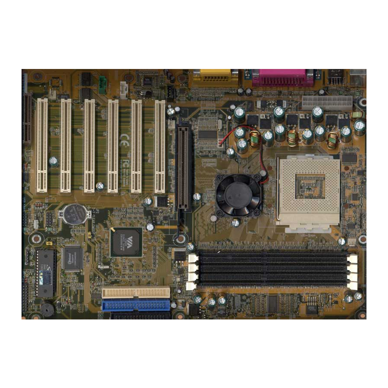
Shuttle HOT-595 User manual

HOT-595
Pentium™processor
Based AGPMAINBOARD
User's Manual

1
NOTICE
Copyright 1997.
AllRightReserved
Manual Ver 1.0
Allinformation, documentation, andspecifications contained inthis manual aresubject to changewithout prior
notificationbythemanufacturer.
The author assumes no responsibility for any errors or omissions which may appear in this document nor does it make a
commitment to update the information contained herein.
TRADEMARKS
All the brands and product names referred to in this manual are trademarks or registered trademarks of their respective
holders.
FCC Notice:
This equipment has been tested and found to comply with the limits for a Class B digital device, pursuant to Part 15 of FCC
Rules. These limits are designed to provide reasonable protection against harmful interference in a residential installation.
This equipment generates, uses and can radiate radio frequency energy. If not installed and used properly, in strict accordance
with the manufacturer's instructions, may cause harmful interference to radio communications. However, there is no guarantee
that interference will not occur in a particular installation. If this equipment does cause interference to radio or television
reception, which can be determined by turning the equipment off and on, the user is encouraged to try to correct the interfer-
ence by one or more of the following measures :
Reorient or relocate the receiving antenna.
Increase the separation between the equipment and receiver.
Connect the equipment into an outlet on a circuit different from that to which the receiver is connected.
Consult the dealer or an experienced radio/television technician for help and for additional suggestions.
The user may find the following booklet prepared by the Federal Communications Commission helpful "How to Identify and
Resolve Radio-TV Interference Problems." This booklet is available from the U.S. Government Printing Office. Washington,
DC 20402, Stock 004-000-00345-4
FCCWarning
The user is cautioned that changes or modifications not expressly approved by the manufacturer could void the users authority
to operate this equipment.
Note: In order for an installation of this product to maintain compliancewith the limits for a Class B device, shielded cables
and power cord must be used.
CE Notice:
Following standards were applied to this product, in order to achieve compliance with the electromagnetic compatibility :
- Immunity in accordance with EN 50082-1: 1992
- Emissions in accordance with EN 55022: 1987 Class B.

2
TABLE OF CONTENTS
T
T
PREFACE ........................................................................................................................3
CHAPTER 1 FEATURES ......................................................................................................4
Accessories of HOT-595 .......................................................................................................................... 6
CHAPTER 2HARDWARE CONFIGURATION.............................................................................7
Jumper Setting........................................................................................................................................... 7
CPUClock Configurations -DIP Switch SW2........................................................................................ 8
SystemClock and CPUMultiplier Setting Manually- SW2 ................................................................ 12
CPUVoltage Setting Manually - SW1................................................................................................... 13
CPUBurst Mode Jumper-JP3................................................................................................................ 14
Flash EEPROM Vpp - JP13................................................................................................................... 14
ClearCMOS -JP6................................................................................................................................... 14
Connectors............................................................................................................................................... 15
CHAPTER 3MEMORY CONFIGURATION ..............................................................................14
CHAPTER 4 FLASH UTILITY .............................................................................................18
CHAPTER 5 VIA VXD AGP DRIVER INSTALLATION ............................................................20
CHAPTER 6 BIOS SETUP ...............................................................................................23
MainMenu .............................................................................................................................................. 24
StandardCMOS Setup............................................................................................................................ 26
BIOS Features Setup............................................................................................................................... 28
Chipset Features Setup............................................................................................................................ 30
PowerManagement Setup ...................................................................................................................... 32
PCIConfiguration Setup......................................................................................................................... 35
Integrated Peripherals ............................................................................................................................. 38
PasswordSetting ..................................................................................................................................... 41

3
P
P
HOT-595mainboard isa highly integrated IBM PC/AT compatible ATX form-factor system
boarddesigned to meet the industry's most demanding desktop applications. Based on the
VIA'sVP3 chipset.
HOT-595accept AMD K5, K6, Intel Pentium P54C, Pentium MMX, IDT-C6 and Cyrix/
IBM6x86, 6x86L, 6x86MX processors and also featureshigh-performance pipelinedburst
secondarycache memory support with size of 1024KB or 512KB. The memory subsystem
isdesigned to support up to 384 MB of EDO RAM andSDRAM inthree 168-pin 3.3 V
DIMMsockets.
HOT-595is equipped withan Accelerated GraphicsPort (AGP) slot,a high performance
interconnectfor graphic-intensiveapplication, suchas 3Dapplications. The AGPis inde-
pendentof the PCIbus andis designed toexclusively use with graphical-display devices.
HOT-595provides a new level of I/O integration. VIA VP3 chipset provides increased
integrationandimprovedperformance over other chipsetdesigns.
TheVIA's VP3 chipset provides an integrated Bus Mastering IDE controller withtwo high
performanceUltra 33DMA IDE interfaces for up to four IDE devices.
TheonboardI/Ocontrollerprovides the standard PCI/Ofunctions:floppyinterface, two
FIFOserial ports,an IrDAdevice portand aSPP/EPP/ECP capableparallel port.
Upto fourPCI localbus slots provide a high bandwidth data path for data-movement
intensivefunctions suchas graphics,and up to three ISA slots complete the I/O function.
HOT-595provides the foundation for cost effective, high performance, highly expandable
platforms,which deliver the latest in Pentium processor and I/O standard.
HOT-595Mainboard is carefully designed for the demandingPC user who wants high
performanceand many intelligentfeatures in acompact package:
PREFACE

4
FEATURES
1
1
Chipset
FeaturesVIA's 82C597VP3 AGP Chipset with I/O subsystems
MainProcessor
AMD K6 166~266 MHz, K5 PR75~PR166,
IntelPentium (P54C) 75~200 MHz, Pentium MMX (P55C) 166~233MHz,
Cyrix/IBM6x86 P120+~P200+,6x86L P200+,6x86MX PR166~PR233,
IDT-C6150~200MHz
SecondaryCache
Onboard1024KB or512KB PipelinedBurst Cache
VersatileMemorySupports
Equippedwith three DIMM sockets for (8, 16,32, 64or 128MB) 168-pin SDRAM memory
modulesup to 384 MB
ExpansionSlots
One AGP slot
FourPCI slot
Three ISA slot
AGPSupport(AcceleratedGraphicsPort)
HOT-595main boardequipped withan AGPslot foran AGPVGA cardthat supports133MHz
2Xmode for texture mapping z-buffering and alphablending. AGP allows3D applications to run
faster and smoothly.
OnboardI/O Chip
One Floppy port
One PS/2 mouse and Keyboard connector
Two high-speed UART compatible serial port
SerialPort 2 can also be directed fromCOM2 tothe Infrared Module for wireless connections
Oneparallelportwith ECP and EPPcapabilities
OnboardPCI Bus MasterIDE Controller
TwoUltra DMA/33 Bus Master IDEPorts supportsfour IDE devices up to33 MB/sec
IDEtransfers and supports Enhanced PIO Modes 3 and 4and BusMaster IDE DMA
Mode2 devices
Onboard20-pinATX PowerSupply
ATXpower supports soft-on/offfunction

5
SystemBIOS
LicensedBIOSwithadditionalfeature:
*FlashEEPROM(128KB) for BIOSupdate
*ISAPlug & Playextension
*Powermanagement
*SupportDMI (Desktop Management Interface) function
ACPI:
SupportACPI(AdvancedConfigurationandPowerInterface) function. ACPI provide
moreEnergy SavingFeatures for the future operating system supporting OS Direct
PowerManagement (OSPM) functionality.
BoardSize:
ATXform factorsize 305mmx 210mm.

6
ACCESSORIESOF HOT-595
Figure 1 : Accessories of HOT-595

7
HardwareConfiguration
2
2
Thischapter is designed for explaininghow to configure the HOT-595'shardware. After youinstall the
mainboard, youcan setjumpers, installmemory onthe mainboard, andmake caseconnectors. Refer to
thischapter whenever youupgrades or reconfigureyour system.
Jumper Setting
Thissection describe the necessary proce-
duresand proper jumpersettings to configure
theHOT-595 mainboard.
Jumperpin headers and DIP Switch show on
rightside are used to configuresystem clock,
CPUmultiplier and CPU voltages.
SystemClock -
Switch1~Switch3of DIP Switch SW2
DIPSwitch SW2 finger 1~3 is used to adjust
SystemClock from 50MHz to 83 MHz.
CPU Multiplier -
Switch4~Switch6of DIP Switch SW2
DIPSwitch SW2 finger 4~6 is used to adjust
CPUcore multiplierfrom 1.5Xto 5.5X.
AutoDetect CPU Voltages Auto/ Figure 2-1 : SW1 & SW2 location
Insertajumperpack on SW1
RowB-CtosetCPUvoltage
auto-detecting
Removejumperpack fromSW1
and insertminion pin1,3,4or
RowA-Btosetvoltage on 3.3V
Switch5issettoON.
Switch1,2,3,4,6aresettoOFF
Switch1,4,5aresettoON
Switch2,3,6aresetup OFF
ManualJumper-SW1
HOT-595automaticallydetectsandadjuststhevoltage to the proper voltage.
Jumperblock SW1 isused to setAutomaticallyor Manually adjustonboard voltages output
fromSwitching type regulators to CPU by inserting or removing mini jumperfrom pin
headers.(please also referto page 13)
Thosehardware settings aremade throughthe use ofDIP Switch and jumper capsto connect
jumperpins on the main board.
Thefollowing examplesshow theconventions usedin thischapter.

8
CPUClock Configuration -DIP Switch SW2
DIPSwitch SW2 and Jumper Block SW1 are the onlySwitch/Jumper that you need to set for your CPU
onHOT-595. Make sure that you know the type of CPU that you are installingand referto the proper
settingswhich are listedbelow. Normally, CPU voltageis auto-detected onHOT-595 and isset to Auto-
detectedwhen HOT-595 is delivered. If you have a higher frequencyCPU or you want to set CPU
frequencyand voltagemanually, pleaserefer tonext twosections.
Intel Pentium (P54C) Series CPUs Settings
ProcessorSpeedFrequency Settings
DIPSwitchSW2
JumperBlock
SW1
Vcore/Vio
Auto-detect
IntelPentium
(P54C)
200 MHzExternal:66MHz
Multiplier:3x
3.3V/3.3V
166 MHzExternal:66MHz
Multiplier:2.5x
150 MHzExternal:60MHz
Multiplier:2.5x
133 MHzExternal:66MHz
Multiplier:2x
120 MHzExternal:60MHz
Multiplier:2x
100 MHzExternal:66MHz
Multiplier:1.5x
90 MHzExternal:60MHz
Multiplier:1.5x
75 MHzExternal:50MHz
Multiplier:1.5x
Table 2-1

9
Intel Pentium MMX (P55C) Series CPUs Settings
ProcessorSpeedFrequency Settings
DIPSwitchSW2
JumperBlock
SW1
Vcore/Vio
Auto-detect
Intel Pentium
P55CMMX
233 MHzExternal:66MHz
Multiplier:3.5x
2.8 V/3.3V
200 MHzExternal:66MHz
Multiplier:3x
166 MHzExternal:66MHz
Multiplier:2.5x
AMD-K6 Series CPUs Settings
ProcessorSpeedFrequency Settings
DIPSwitchSW2
JumperBlock
SW1
Vcore/Vio
Auto-detect
AMD-K6
266 MHzExternal:66MHz
Multiplier:4x
2.2V/3.3V
233 MHzExternal:66MHz
Multiplier:3.5x
233 MHzExternal:66MHz
Multiplier:3.5x3.2V/3.3V
200 MHzExternal:66MHz
Multiplier:3x
2.9V/3.3V
166 MHzExternal:66MHz
Multiplier:2.5x
Note :The voltage of AMD-K6 233MHz may vary from market and CPU core. Please ask your
CPU provider for detail.
Table 2-3
Table 2-2

10
AMD-K6 Series CPUs Settings
ProcessorSpeedFrequency Settings
DIPSwitchSW2
JumperBlock
SW1
Vcore/Vio
Auto-detect
IDT-C6
200 MHzExternal : 66MHz
Multiplier : 3x
3.52V/3.52V
180 MHzExternal : 60MHz
Multiplier : 3x
150 MHzExternal : 60MHz
Multiplier : 2.5x
ProcessorSpeedFrequency Settings
DIPSwitchSW2
JumperBlock
SW1
Vcore/Vio
Auto-detect
AMD-K5
166 MHzExternal:66MHz
Multiplier:1.75x
3.52V/3.52V
133 MHzExternal:66MHz
Multiplier:1.5x
120 MHzExternal:60MHz
Multiplier:1.5x
100 MHzExternal:66MHz
Multiplier:1.5x
90 MHzExternal:60MHz
Multiplier:1.5x
75 MHzExternal:50MHz
Multiplier:1.5x
IDT-C6 Series CPUs Settings
Table 2-4
Table 2-5

11
Cyrix/IBM 6x86/6x86L/6x86MX Series CPUs Settings
ProcessorSpeedFrequency Settings
DIPSwitchSW2
JumperBlock
SW1
Vcore/Vio
Auto-detect
Cyrix/IBM
6x86L
P166+External:66MHz
Multiplier:2x
2.8V/3.3V
P150+External:60MHz
Multiplier:2x
Cyrix/IBM
6x86
P166+External:66MHz
Multiplier:2x
3.52V/3.52V
P150+External:60MHz
Multiplier:2x
P120+External:50MHz
Multiplier:2x
Table 2-6
Cyrix/IBM
6x86MX
PR266 External : 66MHz
Multiplier : 3.5x
2.9V/3.3V
PR233 External : 66MHz
Multiplier : 3x
PR200 External : 66MHz
Multiplier : 2.5x
PR166 External : 60MHz
Multiplier : 2.5x

12
System Clock and CPU Multiplier Setting Manually - SW2
MultiplierSW2
4-5-6 MultiplierSW2
4-5-6 MultiplierSW2
4-5-6
1.5 x 3 x 4.5 x
2 x 3.5 x 5 x
2.5 x 4 x 5.5 x
Forwhom like to set up system manually, listed tables show all theSystem Clock and CPU
Multiplierthat HOT-595 can offer.
Table2-7 showsthe System Clock from 50 MHz to 83 MHz.
Table2-8 showsCPU Multiplier from 1.5X to 5.5X.
Note: On HOT-595 75 and 83 MHz is for over-clock usage, it is not a recommended
generalpractice.
Table 2-8
System
Clock 50MHz 60MHz 66MHz 75MHz 83MHz
PCI
Clock 25MHz 30MHz 33MHz 37.5MHz 41.5MHz
DIP
Switch
SW2
1-2-3
Table 2-7

13
CPU Voltage Setting Manually - SW1
HOT-595automaticallydetectsandadjuststhevoltage to the proper voltage.
Jumperblock SW1 isused to setAutomaticallyor Manually adjustonboard voltages output
fromSwitching type regulators to CPU by inserting or removingmini jumperfrom pin headers.
The voltage settings are made through the use of jumper caps to connect jumper pins on the pin
1~4ofJumperblockSW1.
VoltageSW1VoltageSW1VoltageSW1
Auto
-setting
3.1 V 2.5 V
3.0 V 2.4 V
3.52 V 2.9 V 2.3 V
3.4 V 2.8 V 2.2 V
3.3 V 2.7 V 2.1 V
3.2 V 2.6 V 2.0 V
Table 2-9
Figure 2-2 : SW1 Jumper Block location

14
CMOS Clear - JP6
HOT-595mainboard supports jumper JP6 fordischarging mainboard’s CMOS memory.
Thisjumper canclear theCMOS data stored in the subsystem chip. To clear the CMOS data
pleasefollow listedsteps:
1) Turn off the PC,
2)Remove thejumper cap from JP6 pin 1-2,
3)Insert the jumper cap to JP6 pin 2-3
for a brief while,
4)Remove thejumper cap from JP6 pin 2-3,
5)Reinsert the jumper cap to JP6 pin 1-2,
6) Turn on the PC.
CPU Burst Mode Jumper - JP3
Dueto different designs, there are two kingsof CPU burst modes: Interleave Burst and
LinearBurst. Select the correct mode according to the CPU you are using.
JP3CPUBurstMode
Interleave
(for Pentium/MMX and AMD-K5/K6)
Linear Burst
(ForCyrix/IBM6x86/L/MX)
Whenusing Cyrix/IBM series of CPUs, followthe listed
procedures after select the burst mode:
1. Presee<DEL> keyto enter the BIOS setup menu
duringthe system boot-up,
2. Select"Chipset FeatureSetup",
3. Setthe "Linear Burst" to "Enabled",
4. Press<Esc> to go back the maim menu and choose "Save & ExitSetup" to reboot you
system.
FlashEEPROM Vpp -JP13
HOT-595mainboard supports two typesof Flash EEPROM:
5volt and12 volt.By settingup jumperJP13,
themain board can use both 5V or 12V flash EEPROM
withnew system BIOS files as they come available.
JP13Pin 2-3 Close for12V Flash EEPROM
JP13 Pin 1-2 Close for 5V Flash EEPROM
Figure 2-3: JP3 location

15
Connectors
Front Panel Connectors
Hardware Reset Connector - JP15
Attach 2-pin hardware reset switch to it. Closing the
resetswitch restarts the system.
KeyLock Connector - JP12
KeyLock& Power LED connector is a 5-pin connec-
torfor alock that may be installed on the system case
forenabling or disablingthe keyboard. It also
attached to the case's Power LED. Pin 1 and 3 are for
power LED and pin 4 and 5 are for keylock, pin 2 is
empty.
Speaker Connector - JP11
PCspeaker connector may attach a 4-pin PCspeaker cable from the case to this connector.
SMI Connector - JP10
HardwareSystem Management Interface connector may attach a2-pin momentary switch to it.
Whenpush it will force system get into power saving mode, and thesystem will resume when
switchispushed again.
GLED Connector - JP9
Attacha 2-pin Green LED cable to it. The Green LEDlights when the system get into power
saving mode. The Green LED off when the system resume back to normal mode.
HD LED Connector - JP8
Attacha 2-pinIDE driveLED cableto thisconnector. The LEDlights whenan IDEdevice is
active.
ATX Power On/Off Switch Connector - JP7
Attacha 2-pin momentary type switchto this connector for turningon oroff your ATX power
supply.

16
Back Panel Connectors
COM1/COM2Connectors
AttachCOM1/COM2 device cablesto these connectors.
PS/2 Keyboard & PS/2 Mouse Connector
Two6-pin femalePS/2 keyboard & Mouse Connectors is located at the rear of the main board.
PS/2Mouse on top of connector and PS/2 Keyboard on the bottomof connector. Plugthe PS/2
keyboardand mousejack intothis connector.
Parallel Port Connector
A 25-pin female connector is located at the rear of the main board. Plug the parallel port device
cableintothis connector.
USB1/USB2PortConnectors
Twofemale connectoris locatedat therear ofthe board. Plugthe USBdevices jackinto this
connector.
OtherConnectors
ATX Power Supply Connectors
Itis a twenty-pin male header connector. Plug the connector
fromthe powerdirectly ontothe boardconnector whilemaking
sure the pin 1 is in its position. The main board requires a
powersupply with at least 200 watts and"power goodsignal.
IR Connector - JP5
Infrareddeviceconnector may attacha5-pin infrared device
cableto this connector for enabling the infrared transfer
function. Thismainboard meets thespecification of ASKIR
and HPSIR.

17
CPU, Chassis & AGP cooling Fan
connectors - FAN1, 2 & 3
Themain board providesthree onboard 12Vcooling fan
powerconnectors forCPU (Fan1),Chassis (Fan3) andAGP
device(Fan 2)cooling fan. Depending on the fan maker, the
wiringand plug may be different. The redwire shouldbe
connectedto +12Vand blackwire shouldbe connectedto
ground (GND)
USB1/USB2PortConnectors
Twofemale connectoris locatedat therear ofthe board. Plugthe USBdevices jackinto this
connector.
Wake-On-LAN Connectors
Attacha 3-pin connector from the LAN card which supports the Wake-On-LAN(WOL) func-
tion. This function lets users wake up the connected system through the LAN card.

18
MemoryConfiguration
3
3
TheHOT-595 mainboardprovides three168-pin DIMMsockets thatmake itpossible to
installfrom 8MB upto 384MBof SDRAM andEDO DRAM. The DIMM socket support
8MB,16MB, 32MB,64MB and128MB 3.3Vsingle- ordouble-side SDRAMand EDO
DIMM.
Thethree DIMMsockets are arranged in two banks of one socket each, Each bankprovides
a64/72-bit wide data path.
Thememory configuration tables on nextpage list theDIMMs memoryconfiguration.

19
DIMM 1DIMM 2DIMM 3TOTAL
8MB—— —— 8MB
8MB8MB—— 16 MB
8MB8MB8MB24 MB
16 MB—— —— 16 MB
16 MB16 MB—— 32 MB
16 MB16 MB16 MB48 MB
32 MB—— —— 32 MB
32 MB32 MB—— 64 MB
32 MB32 MB32 MB96 MB
64 MB—— —— 64 MB
64 MB64 MB—— 128 MB
64 MB64 MB64 MB192 MB
128 MB—— —— 128 MB
128 MB128 MB—— 256 MB
128 MB128 MB128 MB384 MB
8MB16 MB—— 24 MB
8MB16 MB16 MB40 MB
16 MB32 MB—— 48 MB
16 MB32 MB32 MB80 MB
32 MB64 MB—— 96 MB
32 MB64 MB64 MB160 MB
64 MB128 MB—— 192 MB
64 MB128 MB128 MB320 MB
Table of contents
Other Shuttle Motherboard manuals

Shuttle
Shuttle AK35GT User manual

Shuttle
Shuttle MB11 User manual

Shuttle
Shuttle Spacewalker AE14 User manual

Shuttle
Shuttle Spacewalker MV11 User manual

Shuttle
Shuttle FS58 User manual

Shuttle
Shuttle Spacewalker MS51 User manual

Shuttle
Shuttle HOT-433 User manual

Shuttle
Shuttle AE23 User manual

Shuttle
Shuttle HOT-675Z User manual

Shuttle
Shuttle FT62 User manual

Shuttle
Shuttle FN45 User manual

Shuttle
Shuttle AK12 User manual

Shuttle
Shuttle MV21 User manual

Shuttle
Shuttle Spacewalker ME17 User manual

Shuttle
Shuttle MS52P User manual

Shuttle
Shuttle AK10 User manual

Shuttle
Shuttle AI61 User manual

Shuttle
Shuttle AT30 User manual

Shuttle
Shuttle Spacewalker AV45GT User manual

Shuttle
Shuttle AV49V User manual