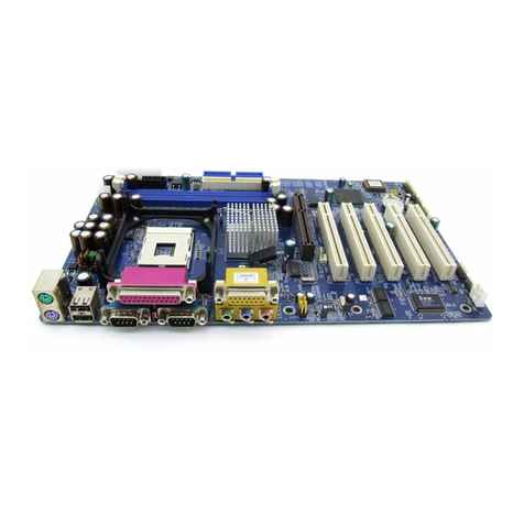
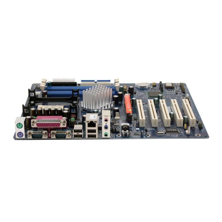
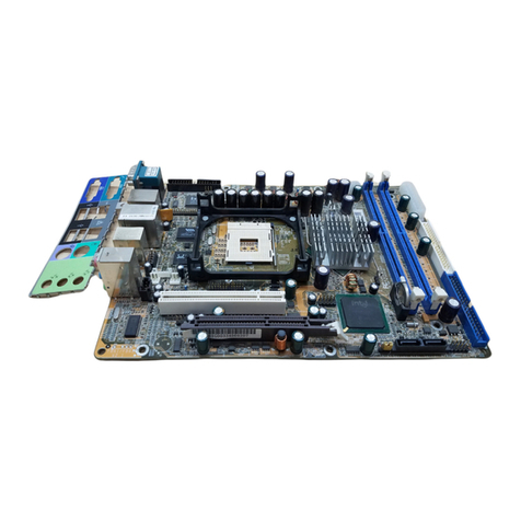
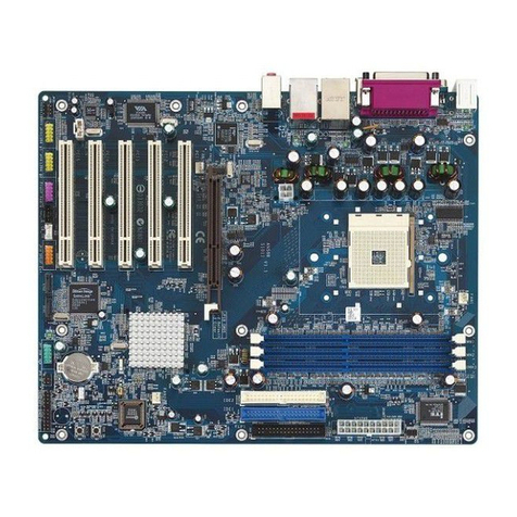
Shuttle HOT-603 User manual

FCC Notice:
This equipment has been tested and found to comply with the limits for a Class B digital device, pursuant to Part 15 of FCC
Rules. These limits are designed to provide reasonable protection against harmful interference in a residential installation.
This equipment generates, uses and can radiate radio frequency energy. If not installed and used properly, in strict accor-
dance with the manufacturer’s instructions, may cause harmful interference to radio communications. However, there is no
guarantee that interference will not occur in a particular installation. If this equipment does cause interference to radio or
television reception, which can be determined by turning the equipment off and on, the user is encouraged to try to correct
the interference by one or more of the following measures :
Reorient or relocate the receiving antenna.
Increase the separation between the equipment and receiver.
Connect the equipment into an outlet on a circuit different from that to which the receiver is connected.
Consult the dealer or an experienced radio/television technician for help and for additional suggestions.
The user may find the following booklet prepared by the Federal Communications Commission helpful “How to Identify
and Resolve Radio-TV Interference Problems.” This booklet is available from the U.S. Government Printing Office.
Washington, DC 20402, Stock 004-000-00345-4
FCCWarning
The user is cautioned that changes or modifications not expressly approved by the manufacturer could void the user’s
authority to operate this equipment.
Note : In order for an installation of this product to maintain compliance with the limits for a Class B device, shielded
cablesandpowercordmustbeused.
CE Notice:
Following standards were applied to this product, in order to achieve compliance with the electromagnetic
compatibility :
- Immunity in accordance with EN 50082-1: 1992
- Emissions in accordance with EN 55022: 1987 Class B.
NOTICE
Copyright 1997.
All Right Reserved
Manual Ver 1.1
All information, documentation, and specifications contained in this manual are subject to change without prior
notification by the manufacturer.
The author assumes no responsibility for any errors or omissions which may appear in this document nor does
it make a commitment to update the information contained herein.
TRADEMARKS
All the brands and product names referred to in this manual are trademarks or registered trademarks of their
respective holders.
M87

2
TABLE OF CONTENTS
PREFACE ...................................................................................................................3
CHAPTER 1 FEATURES.................................................................................................4
Accessories of HOT-603.................................................................................................................. 6
CHAPTER 2HARDWARE CONFIGURATION........................................................................7
Jumper Setting.................................................................................................................................. 7
CPUClockConfigurations - JC1,JP3,JP2 and JP1 ...................................................................... 8
SystemClockand CPUMultiplier onHOT-603............................................................................ 9
CPUVoltageConfiguration -JPW!, JV2,JV3 andJV4 .............................................................. 10
Flash EEPROM Vpp - JVROM1.................................................................................................. 11
ClearCMOS- JVBAT1................................................................................................................. 11
PowerSupplyType Select ............................................................................................................. 12
Connectors & Sockets.................................................................................................................... 13
CHAPTER 3MEMORY CONFIGURATION .........................................................................15
CHAPTER 4 FLASH UTILITY ........................................................................................17
CHAPTER 5 BIOS SETUP ..........................................................................................19
Main Menu ..................................................................................................................................... 20
StandardCMOSSetup ................................................................................................................... 22
BIOS Features Setup ...................................................................................................................... 24
ChipsetFeaturesSetup................................................................................................................... 26
PowerManagementSetup ............................................................................................................. 28
PCIConfigurationSetup................................................................................................................ 30
IntegratedPeripherals .................................................................................................................... 32
PasswordSetting ............................................................................................................................ 35
T
T

3
PREFACE
HOT-603mainboard isahighlyintegratedIBM PC/ATcompatible systemboard. The
designwillaccept AMD K5,K6,Intel Pentium P54C,PentiumMMX and Cyrix/IBM
6x86,6x86L, 6x86MXprocessorsandalsofeatureshigh-performancepipelinedburst
secondary cache memory support with size of 1024KB or 512KB. The memory sub-
systemisdesigned tosupportup to512MB ofEDORAM, StandardFastPage DRAM
andSDRAMin standard72-pin SIMMsocketand 168-pin3.3 VDIMMsocket.
HOT-603providesa new levelof I/O integration. AMD-640chipsetprovides increased
integrationand improvedperformanceoverotherchipset designs. TheAMD-640 chipset
providesanintegrated BusMastering IDEcontrollerwith twohigh performanceUltra33
DMAIDE interfacesforuptofour IDEdevices.
Theonboard I/Ocontroller providesthe standardPC I/Ofunctions: floppyinterface,two
FIFOserialports, an IrDAdevice port andaSPP/EPP/ECP capableparallelport.
Uptofour PCI localbus slots providea high bandwidthdatapath fordata-movement
intensivefunctionssuch as graphics,and up tothree ISA slotscompletethe I/Ofunction.
TheHOT-603 providesthe foundationfor costeffective, highperformance, highly
expandableplatforms, whichdeliverthelatestin Pentiumprocessor andI/O standard.
P
P

4
FEATURES
1
1
TheHOT-603Mainboardiscarefully designedfor thedemandingPCuserwho wantshigh perfor-
manceandmany intelligentfeaturesin a compactpackage:
AMDChipset:
FeaturesAMD-640Chipset withI/Osubsystems.
CPUSupport:
AMD K6 166~266 MHz, K5 PR75~PR166,
IntelPentium75~200 MHz, PentiumMMX166~233 MHz,
Cyrix/IBM6x86 P120+~P166+,6x86LP166+and6x86MX PR166~PR266
SecondaryCache:
Onboard1024KBor 512KB PipelinedBurst Cache.
VersatileMemorySupports:
Equippedwithfour SIMM socketsto support (4,8,16, 32,64and 128MB) 72-pinEDO
orFPmemory modules andthree DIMM socketsto(8, 16,32,64, or 128MB)168-pin
SDRAMmemorymodules up to512 MB.
PCIandISAExpansionSlots:
Providesfour32-bit PCI slotsand three 16-bitISAslots.
OnboardI/OChip:
ProvidesoneFloppy port; oneoptional PS/2 mouseconnector; twohigh-speed UART
compatible serial ports and one parallel port with ECP and EPP capabilities. Serial Port
2canalso bedirectedfrom COM2tothe InfraredModulefor wireless connections.
OnboardPCIBusMasterIDEController:
TwoUltraDMA/33 BusMasterIDE Portssupports four IDEdevices up to33 MB/sec
IDEtransfersand supports EnhancedPIOModes 3 and4 and BusMasterIDE DMA
Mode 2 devices.
Onboard12-pinATand20-pinATXPowerSupply:
ProvidesATand ATXpower connectoronboard.
ATXpowersupports soft-on/off function.
SystemBIOS:
Provideslicensed AwardV4.51PG BIOSon FlashEEPROM.
SupportsGreen PC,DMIandBundledwith SymbiosLogin(NCR) SDCMV4.0 SCSI
BIOS.

5
ACPI:
SupportACPI (AdvancedConfiguration andPowerInterface)function. ACPIprovide
moreEnergySaving Featuresforthe future operatingsystem supporting OSDirect
PowerManagement(OSPM)functionality.
BoardSize:
3/4babyAT compact size220mmx 280mm.

6
ACCESSORIESOFHOT-603

7
HardwareConfiguration
Jumper Setting
Jumperpinheaders showon rightside
areusedto configuresystemclock,
CPUmultiplierand CPU voltages.
SystemClock -JC1
JC1isa 6-pins headerjumper which
is used to adjust System Clock from
50MHz to 83 MHz.
CPUMultiplier- JP1,JP2andJP3
JP1,JP2 andJP3are3-pinsheader
jumperwhichis usedtoadjust CPUcoremultiplier from1.5Xto 5.5X.
CPUVoltages
JPW1,JV2,JV3 and JV4areused toadjustonboard voltages outputfromSwitching
typeregulatorsto CPU byinsertingor removing minijumperfrom pin headers.
Thosehardwaresettings aremadethrough theuseof jumpercapsto connect jumper
pins on the main board. The jumpers will be show graphically such as to connect
pins 3&4 and 5&6, and to connect pins 1&2 and 3&4 for six pin jumpers.
Jumpers will be show graphically such as to connect pins 2&4 and to
connectpins3&4 for fourpin jumpers.
Jumpers with two pins will be shown as for Short (On) and for Open (Off).
Toconnectthe pins, simplyplacea plastic jumpercapover the twopinsas dia-
gramed.
2
2

8
CPU Clock Configuration - JC1, JP3, JP2 and JP1
ProcessorsJC1System
Clock
/Multiplier
Multiplier
JP3/JP2/JP1
AMD-K6266 MHz66 MHz
x4
AMDK6233 MHz,
PentiumMMX233 MHz.
Cyrix/IBM6x86MXPR266
66 MHz
x3.5
AMD-K6200 MHz,
AMD-K5PR200,
PentiumMMX200 MHz,
Pentium200 MHz,
Cyrix/IBM6x86MXPR233
66 MHz
x3
Cyrix/IBM6x86LP200+,
Cyrix/IBM6x86 P200+75 MHz
x2
AMD-K6166 MHz,
AMD-K5PR166,
PentiumMMX166 MHz,
Pentium166 MHz,
Cyrix/IBM6x86MXPR200
66 MHz
x2.5
PentiumMMX150 MHz,
Pentium150 MHz,
Cyrix/IBM6x86MXPR166
60 MHz
x2.5
Pentium133 MHz,
Cyrix/IBM6x86LP166+,
Cyrix/IBM6x86 P166+
66 MHz
x2
Pentium120 MHz,
Cyrix/IBM6x86LP150+,
Cyrix/IBM6x86 P150+
60 MHz
x2
Cyrix/IBM6x86 PR133+55 MHz
x2
Cyrix/IBM6x86 P120+50 MHz
x2
AMDK5PR100/PR133,
Pentium100 MHz66 MHz
x1.5
AMD-K5PR90/PR120,
Pentium90 MHz60 MHz
x1.5
AMD-K5PR75,
Pentium75 MHz50 MHz
x1.5
Table 2-1

9
SystemClockandCPUMultiplieronHOT-603
MultiplierJP3/JP2/JP1
1.5X
2X
2.5X
3X
3.5X
4X
4.5X
5X
5.5X
SystemClock JC1
50 MHz
55 MHz
60 MHz
66 MHz
75 MHz
83 MHz
For whom like to set up system manually, listed tables show all the System Clock and CPU
MultiplierthatHOT-603 can offer.
Table2-2shows theSystemClock from 50MHz to 83MHz.
Table2-3shows CPUMultiplierfrom 1.5X to5.5X.
Note: SincePCIclock ishalfof systemclock,75MHz and83MHzsystemclocks may
causePCIclockbeyondPCIspecification.
Table 2-2
Table 2-3

10
Voltage CPU Type Jumper-Setting
Type Vcore Vio JPW1 JV3 JV4 JV2
Single
3.52V 3.52V 3.52V AMD K5 ABx,
Pentium P54C VRE,
Cyrix/IBM 6x86
3.3V 3.3V Pentium P54C STD,
Cyrix/IBM 6x86
Dual
3.2V 3.3V AMD-K6
233 / 266 MHz
2.9V 3.3V AMD-K6
166 / 200 MHz,
Cyrix 6x86MX
2.8V 3.3V Pentium P55C
MMX,
Cyrix 6x86L
2.1V 3.3V AMD-K6
266 / 300 MHz
CPU Voltage Configuration - JPW1, JV2, JV3 and JV4
Table 2-4
3.45V
3.3V

11
FlashEEPROMVpp-JVROM1
HOT-603mainboardsupports two typesofFlash EEPROM:5volt and 12volt.By
settingupjumper JVROM1, themain board canuseboth 5Vor12V flash EEPROMwith
newsystemBIOSfilesas theycome available.
JVROM1Pin2-3 Close for5VFlash EEPROM
JVROM1Pin1-2 Close for12VFlash EEPROM
ClearCMOS-JVBAT1
HOT-603 mainboardsupports jumper JVBAT1for discharging mainboard'sCMOS
memory.
Thisjumpercan clear theCMOSdata storedinthe sub-system chip. Toclear the CMOS
dataplease followlisted steps:
1) Turn off the PC,
2)Removethe jumpercapfrom JVBAT1 pin1-2,
3)Insertthe jumper captoJVBAT1 pin 2-3fora brief while,
4)Removethe jumpercapfrom JVBAT1 pin2-3,
5)Reinsertthe jumper captoJVBAT1 pin 1-2,
6) Turn on the PC.

12
HOT-603provideboth ATand ATX powerconnector on-board, ATandATX power
supplyareavailable on HOT-603. JumperAT-Pis used toset what typeofpower supply is
plugedtothe main board.
Power Supply Type Outline J1
12-Pin AT Type
20-Pin ATX Type
PowerSupplyTypeSelect
Table 2-5

13
Connectors&Sockets
IDE, Floppy, Parallel and Serial port
connectors
Themainboard shipped withone40-pin ribbon cablefor IDE
H.D.D,one 34-pinribboncable forF.D.D,one 25-pinribbon
cablefor printerandtwo 9-pinribbon cablefor COMport
devices. Ribboncablesshouldalwaysbe connectedwith the
red stripe on the Pin 1 side of the connector.
PS/2 Mouse connector
Themainboard provides aminiDIN connec-
torora 6 pinsPS/2 mouse headerforoptional
PS/2mousecable. Diagram on therightside
indicatesthepinout of the6-pin header.
HOT-603mainboardsuppliestwotypes
ofoptional PS/2mouseadapter cable,
type1have 6-holesplugwith hole 2and
hole6wireless; type 2have5-holes plug
withhole2 wireless.
Caution:When a PS/2mouseis used,
makesureconnect PS/2mouseadapter
cable hole 1 to the pin 1 of onboard PS/2
connector(CN5). Reversedconnecting maycause damageto
yourPS/2mouse.
Connectors&Sockets
ITEM FUNCTION ITEM FUNCTION
SIM1,2,3,4On-boardSIMM socketsJUSB1 UniversalSerialBus(USB)Connectors
DIMM1,2,3On-board3.3VDIMM socketsIR1/IR2 Infra-Red/FastInfra-RedConnectors
PCI1,2,3,4On-boardPCISlotsFAN1 Cooling FanConnector
SL1,3,5On-boardISASlotsJ4 GreenLED
IDE1 On-boardPCIPrimaryIDEConnectorHDLED1 On-boardEnhancedIDER/WLEDConnector
IDE2 On-boardPCISecondaryIDEConnectorJ2 HardwareResetSwitchConnector
CN7 On-boardFloppy ControllerConnectorJ3 PowerLEDand KeylockConnector
PRINT1 On-boardParallelPortConnectorJ5 PCSpeakerConnector
COM1 On-boardSerialport-1ConnectorCN3 ATXPowerSupplyConnector
COM2 On-boardSerialPort-2ConnectorCN6 ATPowerSupplyConnector
CN5 On-boardPS/2MousePortConnectorPWRBTN1 MomentaryTypeATXPowerSwitching Connector
JPON1 PermanentTypeATXPowerSwitchConnector
Table 2-6

14
USB1,USB2-USBconnectors
Themainboard provides twosets USB (UniversalSerialBus)
connectors- USB1andUSB2forUSB devicesuse.
IR1, IR2 - Infrared module
connectors
Themainboard providesa5-pin infraredand
fast infrared connectors as an optional
infrared module for wireless transmitting and
receiving.
FAN1- 12V cooling fan power con-
nector
Themainboard provides anonboard 12V coolingfanpower
connectorwhichprovide maximum100
mAMP(1.2W)current eachforCPUcoolingfan.
Dependingonthe fan maker,thewiring and plug
maybedifferent. The redwireshould be con-
nectedto+12V and blackwireshould be con-
nectedto ground(GND).
J4 - Green LED connector
J4isa 3-pin GreenLEDconnector, the usercanconnect a LED
onitto displaypower managementstatus.
PWRBTN1 - ATX Power Switch But-
tonConnector
(Availableonlywhen ATX powersupplyis used).
Thesystempowercanbe controlledby amomentaryswitch
connector. Pushingtheswitch buttonwillturn the systemoff .
Note:
WhenaATPowerSupplyisusedtoHOT-603,
pleasedonotconnectanymomentaryswitchto
PWRBTN1.
ATandATXPowerconnectors
Themainboard provides bothAT and ATXPowercon-
nector. ATXpower supportssoftpoweron/offfunction.

15
MemoryConfiguration
3
3
TheHOT-603mainboard providesfour72-pin SIMMsocketsand three168-pin
DIMMsocketsthat makeit possible toinstall upto512MB ofRAM. TheSIMM
socketsupport4MB, 8MB,16MB,32MB, 64MB and128MB 5V single-or
double-sidefastpage orEDO DRAM modules,and DIMMsocketsupport 8MB,
16MB,32MB,64MB, and128MB 3.3V single-or double-sideSDRAM,fast page,
orEDOmodules.
ThefourSIMM socketsarearranged intwo banks oftwo sockets each,the three
DIMMsocketare arranged intwo banks ofonesocket each. Eachbankprovides a
64/72-bitwide datapath.
Note:
Maximum memory size is 512MB total for all SIMM.
Maximum memory size is 384MB total for all DIMM.
If using SIMM modules, each bank must be filled with a pair of same
modules.
The user should not populate both 5V SIMM modules & 3.3V DIMM
modules at the same time.
Thememoryconfiguration tableson nextpage listtheSIMMs andDIMMs
memory configuration.

16
SIM1SIM2SIM3SIM4DIM1DIM2DIM3TOTAL
4MB4MB—— —— —— —— —— 8MB
4MB4MB4MB4MB—— —— —— 16 MB
8MB8MB—— —— —— —— —— 16 MB
4MB4MB8MB8MB—— —— —— 24 MB
8MB8MB8MB8MB—— —— —— 32 MB
16 MB16 MB—— —— —— —— —— 32 MB
4MB4MB16 MB16 MB—— —— —— 40 MB
8MB8MB16 MB16 MB—— —— —— 48 MB
16 MB16 MB16 MB16 MB—— —— —— 64 MB
32 MB32 MB—— —— —— —— —— 64 MB
4MB4MB32 MB32 MB—— —— —— 72 MB
8MB8MB32 MB32 MB—— —— —— 80 MB
16 MB16 MB32 MB32 MB—— —— —— 96 MB
32 MB32 MB32 MB32 MB—— —— —— 128 MB
64 MB64 MB—— —— —— —— —— 128 MB
4MB4MB64 MB64 MB—— —— —— 136 MB
8MB8MB64 MB64 MB—— —— —— 144 MB
16 MB16 MB64 MB64 MB—— —— —— 160 MB
32 MB32 MB64 MB64 MB—— —— —— 192 MB
64 MB64 MB64 MB64 MB—— —— —— 256 MB
128 MB128 MB—— —— —— —— —— 256 MB
128 MB128 MB128 MB128 MB—— —— —— 512 MB
—— —— —— —— 8MB—— —— 8MB
—— —— —— —— 8MB8MB—— 16 MB
—— —— —— —— 8MB8MB8MB24 MB
—— —— —— —— 16 MB—— —— 16 MB
—— —— —— —— 16 MB16 MB—— 32 MB
—— —— —— —— 16 MB16 MB16 MB48 MB
—— —— —— —— 32 MB—— —— 32 MB
—— —— —— —— 32 MB32 MB—— 64 MB
—— —— —— —— 32 MB32 MB32 MB96 MB
—— —— —— —— 64 MB—— —— 64 MB
—— —— —— —— 64 MB64 MB—— 128 MB
—— —— —— —— 64 MB64 MB64 MB192 MB
—— —— —— —— 128 MB—— —— 128 MB
—— —— —— —— 128 MB128 MB—— 256 MB
—— —— —— —— 128 MB128 MB128 MB384 MB
—— —— —— —— 8MB16 MB—— 24 MB
—— —— —— —— 8MB16 MB16 MB40 MB
—— —— —— —— 16 MB32 MB—— 48 MB
—— —— —— —— 16 MB16 MB32 MB64 MB
—— —— —— —— 16 MB32 MB32 MB80 MB
—— —— —— —— 32 MB64 MB—— 96 MB
—— —— —— —— 32 MB32 MB64 MB128 MB
—— —— —— —— 32 MB64 MB64 MB160 MB
64 MB64 MB128 MB256 MB
—— —— —— —— 64 MB128 MB128 MB320 MB

17
Flash Utility
Thischapterbriefly discussesAward Flashutility providesinstructionsto guideyou
throughupdatingyour oldBIOS. Thefile name weuse to programhere is test.bin,and
the file name to save old BIOS is 603.OLD. Please note that those file names are not
absolute. Theyareonly examplestolet youhavea moreclearunderstanding ofthe
updatingprocess.
How to Begin
1. Pleasetype“awdflash”andpress theENTER keyto begintheupdating process.
2. Onceyouenter, youwillsee amain menu displaying:
3. Move the cursor to “File Name to Program: “
4. Typetheprogram name“test.bin”,and thenpressthe ENTERkey.
5. Atthebottom ofthemenu, you willbe requested toanswer:
“DoYouWantto Save BIOS (Y/N)? “
Thefollowingmanual is intendedtoguide you throughthe process ofboth“No” and
“Yes”casesrespectively.
If “No”
If you do not wish to save the old BIOS:
1. Pleasetype“N”, andthenpress the ENTERkey.
2. Then you will be requested to answer:
“AreYouSure toProgram? “
3. Answer “N” if you do not want to program, and then it will exit.
4
4

18
If “Yes”
Tosavethe old BIOS:
1. Pleaserespond“Y”, andthenpress the ENTERkey.
2. Move the cursor to “File Name to Save: “
3. Typefilename “603.OLD”, andthen press theENTER key. (YouroldBIOS willbe
saved in the file name you create. In this case, the old BIOS is saved in the file name,
603.OLD).
4. Then you will be requested to answer:
“AreYouSure to Program (Y/N)? “
5. Type“Y”to begin programming,andpress the ENTERkey.
6. Whentheprogramming isfinished, theshowing messagewillappear:
7. Onceyousee theshowing message “PowerOff orResetSystem”, pleasere-startyour
system.
8. Whenyoupower on thecomputer again, youwill find youroldBIOS hasalready
beensuccessfullyupdated.
Toviewa complete usageof FLASH utility,pleasetype “awdflash /?”andpress the
ENTER key.
Notes About Award Flash Utility
Pleasenotethat AwardFlash Utilitycannot rununder EMM386 orQEMM. Thus,when
executingthecommand “awdflash”,anerror message willappear:
“ErrorMessage: Fail—Due to EMM386orQEMM !”

19
BIOS Setup
HOT-603BIOSROM has abuilt-inSetup program thatallows users tomodifythe basic
systemconfiguration. Thistype of informationis stored inbattery-backed RAM sothatit
retains the Setup information when the power is turned off.
Entering Setup
Poweronthe computer andpress <Del> immediatelywillallow youtoenter Setup. The
otherwayto enterSetupis topoweron thecomputer,when thebelowmessage appear
brieflyatthe bottom ofthescreen during thePOST(Power On SelfTest),press <Del>
keyorsimultaneously press<Ctrl>,<Alt>,and <Esc>keys.
"TOENTERSETUPBEFOREBOOTPRESSCTRL-ALT-ESCORDELKEY"
Ifthemessage disappearsbefore yourespondand youstill wishto enterSetup,restart the
systemtotry again byturningit OFFtheON or pressingthe "RESET" buttononthe
systemcase. Youmay also restartbysimultaneously press <Ctrl>,<Alt>,and<Delete>
keys. If you do not press the keys at the correct time and the system does not boot, an
errormessagewill bedisplayedand you willagain be askedto,
"PRESSF1TOCONTINUE,CTRL-ALT-ESCORDELTOENTERSETUP"
5
5

20
Main Menu
Standard CMOS setup
Thissetuppage includes allitemsin a standardcompatible BIOS.
BIOS features setup
Thissetuppage includesall items of Awardspecial enhancedfeatures.
Chipset features setup
Thissetuppage includes allitemsof chipset features.
Power Management Setup
Thissetuppage includesallitems ofPower Management features.
PnP/PCI Configuration setup
Thisitemspecifies the value(inunits of PCIbusblocks) of thelatencytimer for the
PCIbusmaster and theIRQlevel forPCIdevice. Power-on withBIOSdefaults
Load BIOS Defaults
BIOSdefaultsloads the valuesrequiredby the Systemforthe maximum performance.
However,youcan changetheparameter througheach Setup Menu.
LoadSetup Defaults
Setupdefaultsloads the valuesrequiredby the systemforthe O.K. performance.
However,youcan changetheparameter througheach Setup Menu.
Table of contents
Other Shuttle Motherboard manuals

Shuttle
Shuttle Spacewalker AV32 User manual

Shuttle
Shuttle HOT-675 User manual

Shuttle
Shuttle MS52P User manual

Shuttle
Shuttle MV43VN User manual

Shuttle
Shuttle AK37GT User manual

Shuttle
Shuttle FN85 User manual

Shuttle
Shuttle DL30N Series User manual

Shuttle
Shuttle FV24 User manual

Shuttle
Shuttle AN50R User manual

Shuttle
Shuttle HOT-565 User manual

Shuttle
Shuttle AV42 User manual

Shuttle
Shuttle FB77 User manual

Shuttle
Shuttle HOT-673 User manual

Shuttle
Shuttle Spacewalker AV40S User manual

Shuttle
Shuttle FB61 User manual

Shuttle
Shuttle AK32A User manual

Shuttle
Shuttle MS11 User manual

Shuttle
Shuttle MB11 User manual

Shuttle
Shuttle FB62 User manual

Shuttle
Shuttle Spacewalker AK31 User manual