Chapter 2Technical Information
TiM55x/56x/57x/58x | 2D LiDAR sensors
6©SICK AG · Germany · All rights reserved · Subject to change without notice 8015883/122G/2018-12-06
Operating principle of the TiM5xx
2Operating principle of the TiM5xx
2.1 Measurement principle
The TiM5xx is an opto-electronic laser scanner that electro-sensitively scans the perimeter
of its surroundings at a single plane with the aid of laser beams. The TiM5xx measures its
surroundings using two-dimensional polar coordinates based on its measurement origin.
This is marked on the hood in the centre using a circular indentation. If a laser beam hits
an object, its position in terms of distance and direction is determined.
Scanning is performed across a 270° sector. The maximum range of the TiM5xx is max.
10 m (TiM55x/TiM56x) and 25 m (TiM57x/TiM58x) on light, natural surfaces with an object
reflectivity > 50 % (e.g. a white house wall).
The scanning range is 8 m in the case of dark surfaces with remission of > 10%.
2.2 Distance measurement
The TiM5xx emits pulsed laser beams using a laser diode. If one of these laser pulses hits
an object or a person, this is reflected at its surface. The reflection is detected in the
TiM5xx's receiver by a photodiode. The TiM5xx uses HDDM / HDDM+ technology (High Defi-
nition Distance Measurement), a SICK own-development. Using this measurement method,
a measured value is formed by the average value for several individual pulses. The TiM5xx
calculates the distance to the object from the transit time required by the light from emis-
sion of the beam to receipt of the reflection. This principle of "time-of-flight measurement"
is used by radar systems in a similar manner.
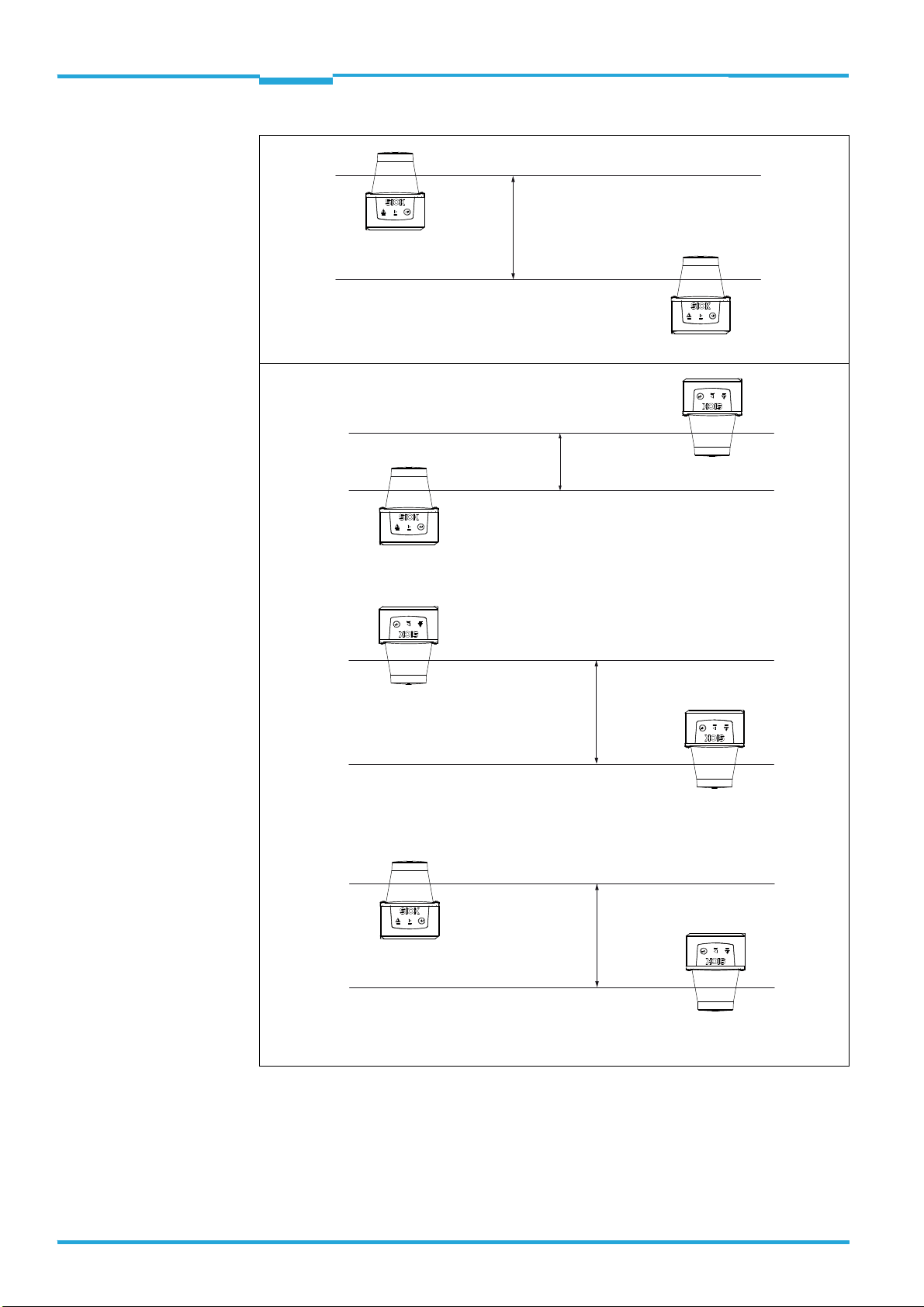
2.3 Direction measurement
The emitted laser beams are deflected by the TiM5xx using a rotating mirror and its sur-
roundings scanned in a circular form. The measurements are triggered internally at regular
angle increments using an angular encoder. One complete rotation represents one measur-
ing process (scan).
The TiM5xx works at a scanning frequency of 15 Hz, i.e. it performs 15 measuring processes
per second and makes the measurement results continuously available in real time via an
Ethernet interface.