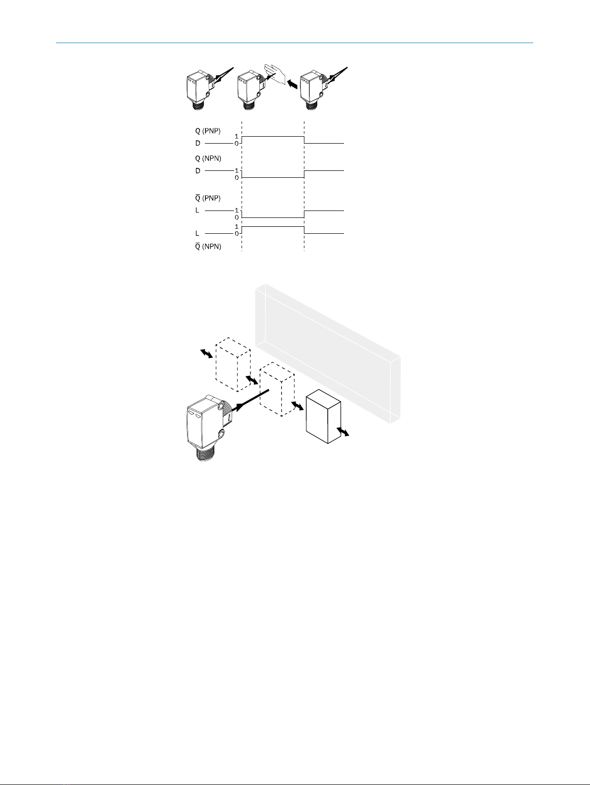
dark switching light switching
2 1 t = 1
1 2 t = 2
Timer stages can be set from 0 to 2 seconds.
Light/dark switch: The sensor is in light switching mode when optional light/dark poten‐
tiometer is rotated to the “L” position. The sensor is in dark switching mode when
optional light/dark potentiometer is rotated to the “D” position. The green power supply
LED will flash once when the mode is changed.
6 Fault diagnosis
Table indicates which measures are to be taken if the sensor stops working.
7 Table Fault diagnosis
LED indicator/fault pattern /
LED indicator/fault pattern
Cause /
Cause
Measures /
Measures
Green LED does not light up /
Green LED does not light up
No voltage or voltage below
the limit values /
No voltage or voltage below
the limit values
Check the power supply,
check all electrical connec‐
tions (cables and plug connec‐
tions) /
Check the power supply,
check all electrical connec‐
tions (cables and plug connec‐
tions)
Green LED does not light up /
Green LED does not light up
Voltage interruptions /
Voltage interruptions
Ensure there is a stable power
supply without interruptions /
Ensure there is a stable power
supply without interruptions
Green LED does not light up /
Green LED does not light up
Sensor is faulty /
Sensor is faulty
If the power supply is OK,
replace the sensor /
If the power supply is OK,
replace the sensor
Yellow LED flashes; if Health is
present then take note of the
corresponding output signal; if
Alarm is present then take note
of the corresponding output
signal /
Yellow LED flashes; if Health is
present then take note of the
corresponding output signal; if
Alarm is present then take note
of the corresponding output
signal
Sensor is still ready for opera‐
tion, but the operating condi‐
tions are not ideal/addition‐
ally with health output: power
supply interrupted /
Sensor is still ready for opera‐
tion, but the operating condi‐
tions are not ideal/addition‐
ally with health output: power
supply interrupted
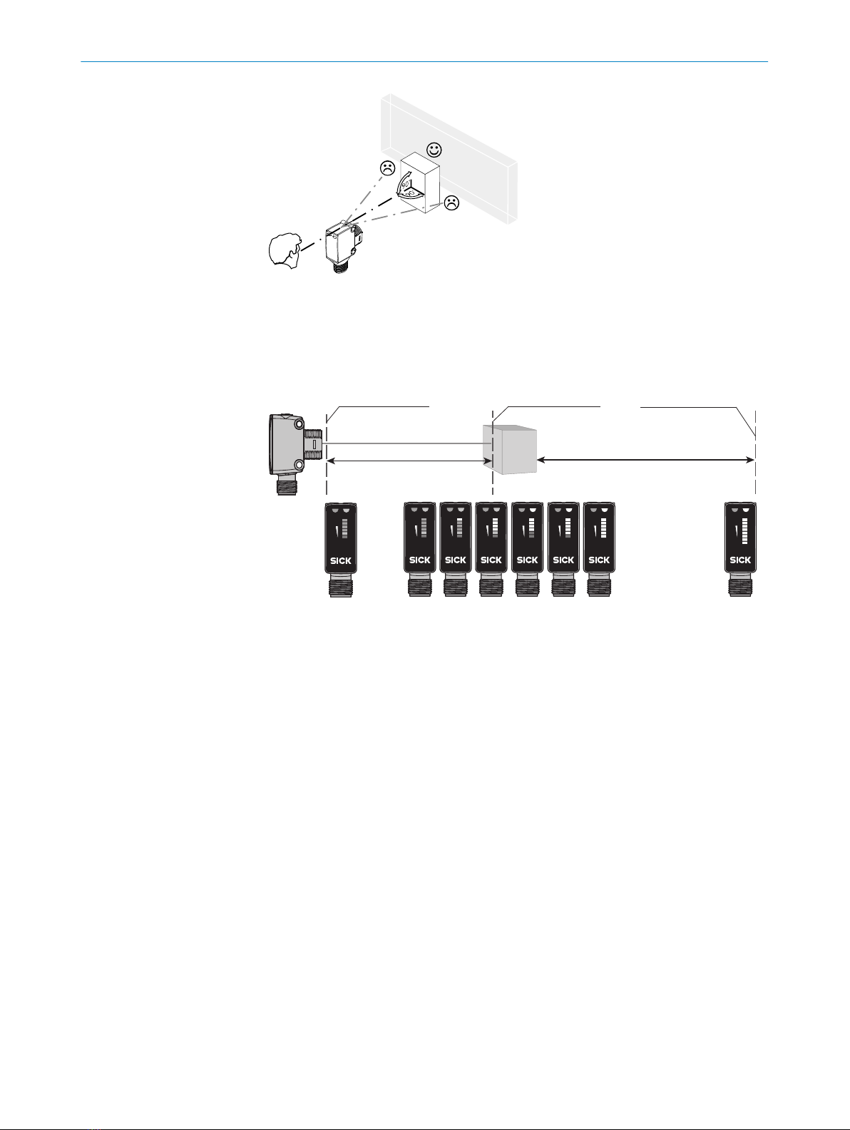
Check the operating condi‐
tions: Fully align the beam of
light (light spot) with the back‐
ground. / Clean the optical
surfaces . / Readjust the sen‐
sitivity (potentiometer) /
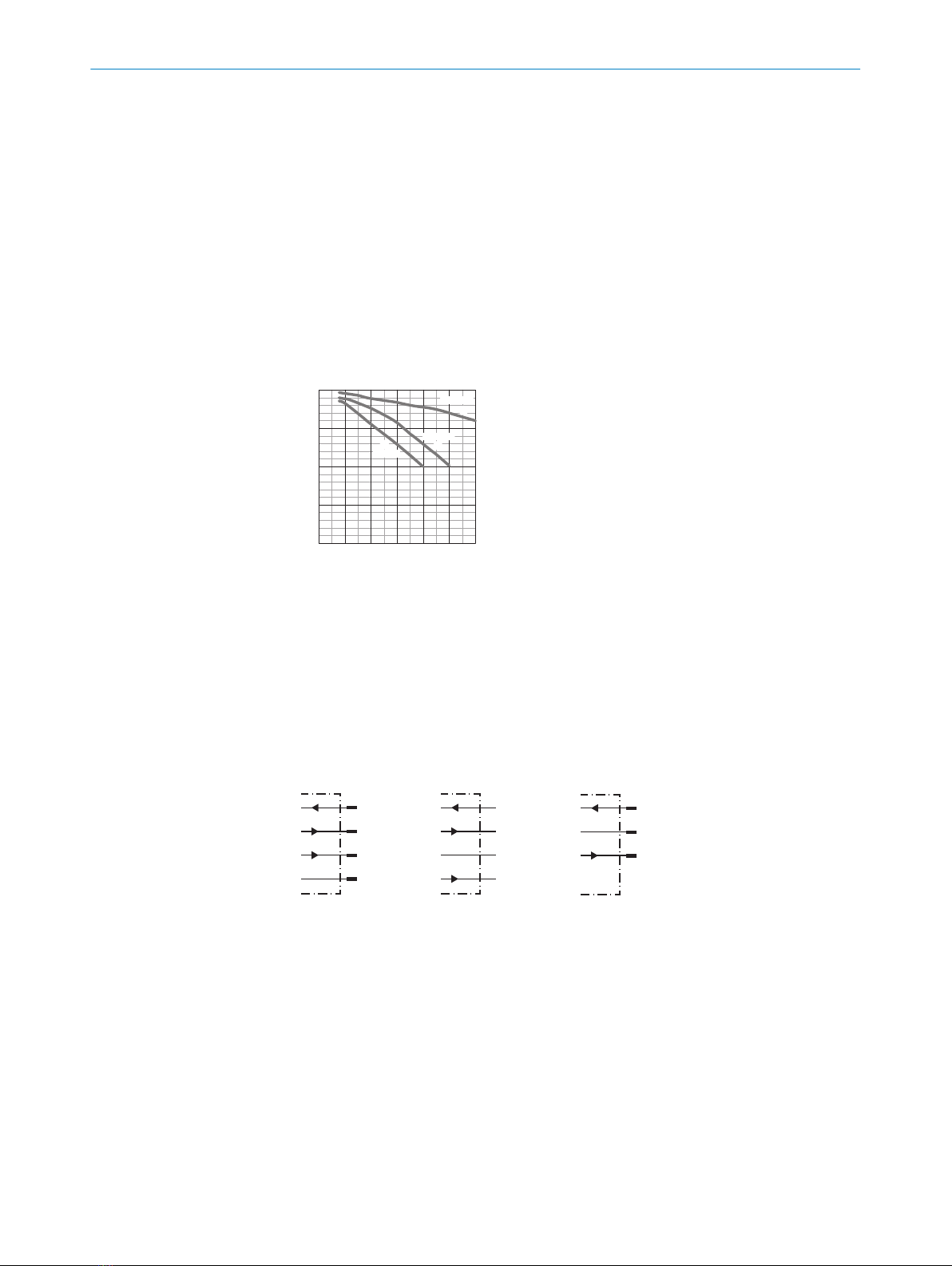
Check sensing range and
adjust if necessary; see
graphic F. / With health out‐
put: Check the power supply,
check all electrical connec‐
tions (cables and plug connec‐
tions). /
Check the operating condi‐
tions: Fully align the beam of
light (light spot) with the back‐
ground. / Clean the optical
surfaces . / Readjust the sen‐
sitivity (potentiometer) /
Check sensing range and
adjust if necessary; see
graphic F. / With health out‐
FAULT DIAGNOSIS 6
8017859 | SICK
Subject to change without notice 5