Table 4: Test
Test
7 Commissioning
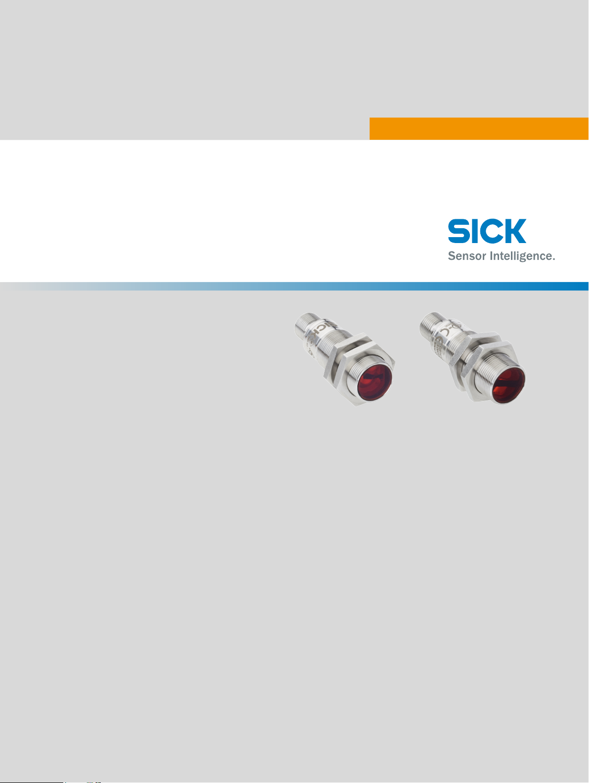
7.1 Alignment
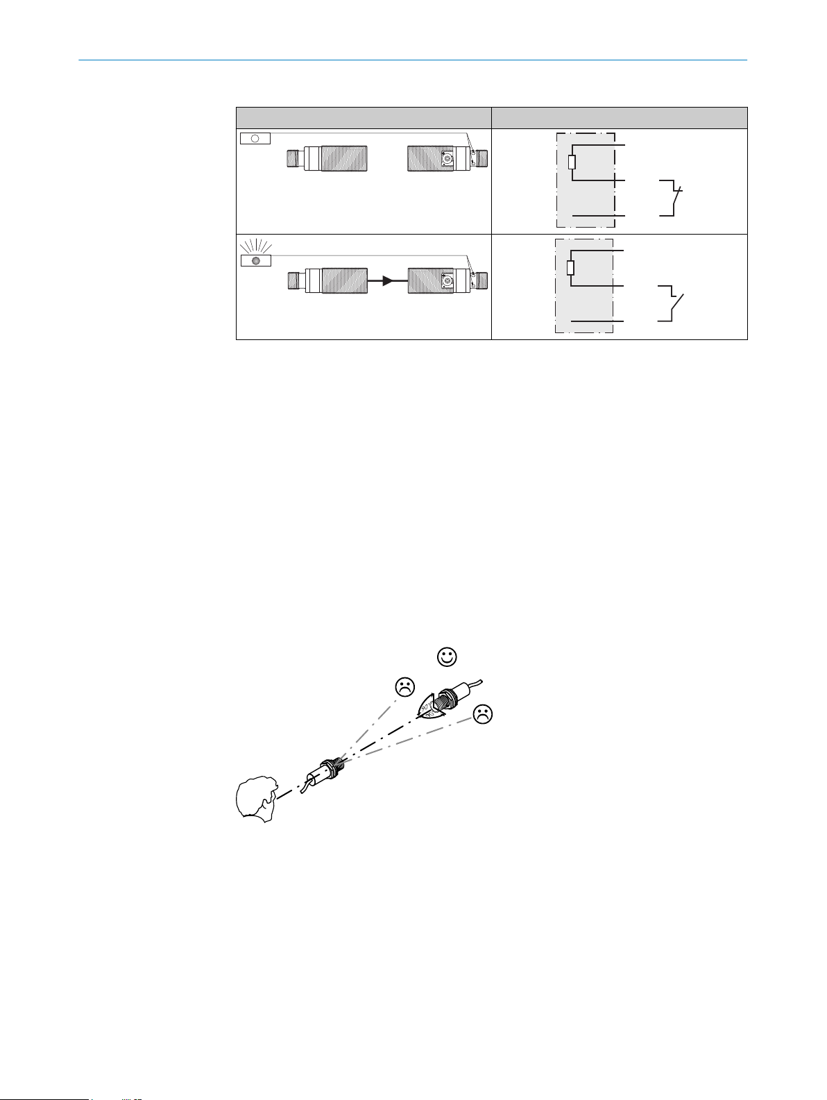
Align the sender with the receiver. Select the position so that the red emitted light beam
hits the receiver. Tip: Use white paper or a reflector as an alignment aid. The sender
must have a clear view of the receiver, with no object in the path of the beam [see
figure 3]. You must ensure that the optical openings (front screen) of the sensors are
completely clear.
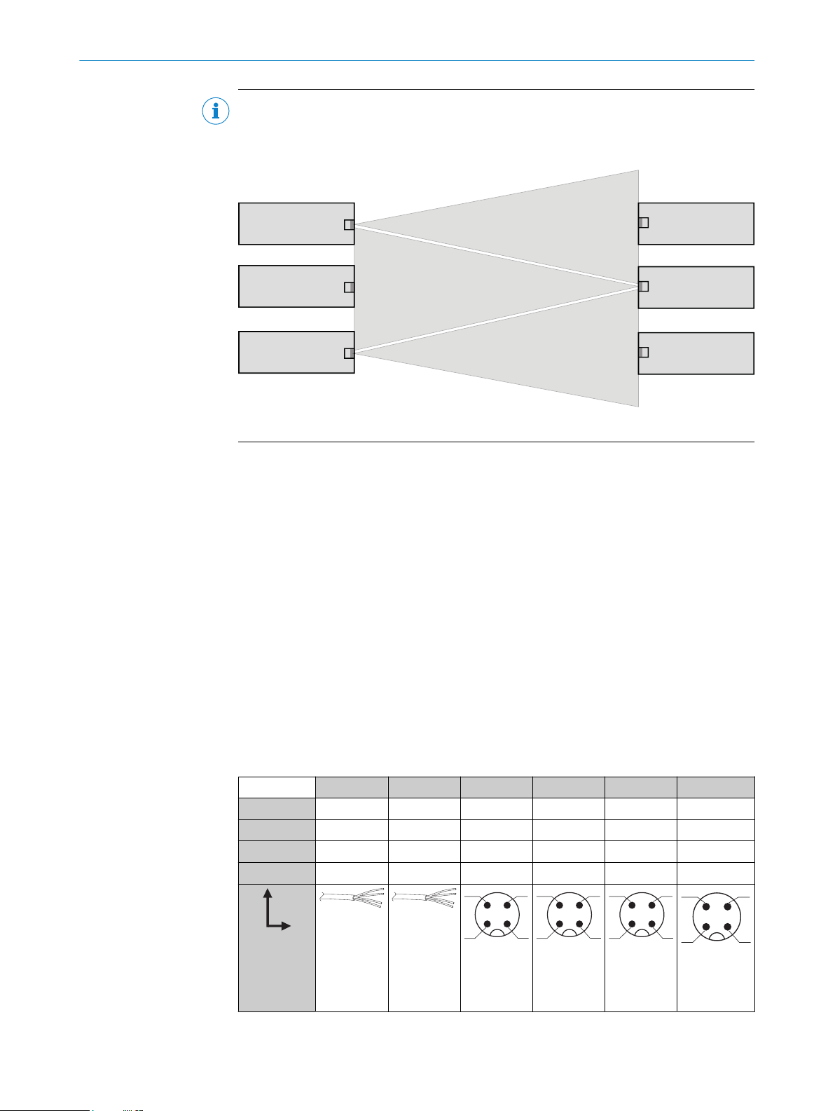
Align the sender with the receiver. Select the position so that the infrared light (not
visible) hits the receiver. The correct alignment can only be detected via the LEDs. See
figure 3 and table 3. The sender must have a clear view of the receiver, with no object
in the path of the beam. You must ensure that the optical openings (front screen) of the
sensors are completely clear.
Figure 3: Alignment
7.2 Check the application conditions
Observe the application conditions: Adjust the distance between the sender and the
receiver according to the corresponding diagram [see figure 0] (x = sensing range, y =
operating reserve).
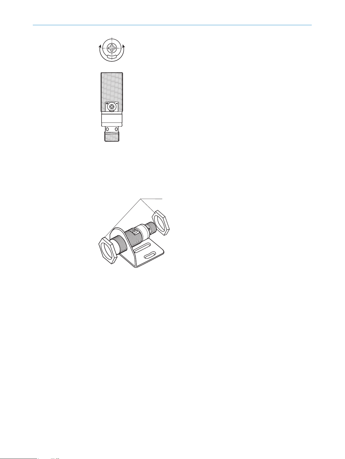
If several through-beam photoelectric sensors which are installed next to one another
are to be used, we recommend swapping the sender/receiver arrangement at every
second through-beam photoelectric sensor and ensuring that there is sufficient dis‐
tance between the through-beam photoelectric sensors. By doing this, mutual interfer‐
ence can be prevented [see figure 2].
COMMISSIONING 7
8021182.1ABM / 2020-12-21 | SICK
Subject to change without notice 9