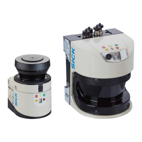
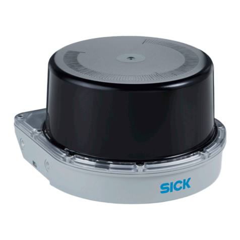
SICK LMS1 Series User manual

Laser Measurement Sensors
of the LMS1xx Product Family
In full view in all weathers –
compact and economical
OPERATING INSTRUCTIONS

2©SICK AG · Germany · All rights reserved · Subject to change without notice 8012471/UT27/2012-02-14
Software version Operating Instructions
Laser Measurement Sensors of the LMS100 Product Family
Software version described
Software access to the LMS100/LMS111/LMS151 is password protected. In the default
delivery status the following passwords are defined:
The software access to the LMS12x/LMS13x and LMC12x/LMC13x is described in the
document ”Technical Information (installer instructions VdS)”, part no.: 8013749, issue in
English.
Software/tool Function Status
LMS100/LMS111/LMS151-
10000
Firmware V 1.40
LMS12x/LMS173/LMS13x/
LMS182
LMC12x/LMC13x
Firmware V 1.11
Device description
LMS100/LMS111/LMS151
Device specific software module
for SOPAS ET
V01.14.00 or higher
Device description
LMS121/LMS122/LMS123/
LMS173/LMS131/LMS132/
LMS133/LMS182
Device specific software module
for SOPAS ET
V01.11.00 or higher
LMC12x/LMC13x Device specific software module
for SOPAS ET
V01.00.00 or higher
SOPAS ET Configuration software V 02.32 or higher
User level Password
Maintenance personnel main
Authorized client client
Copyright
Copyright © 2008-2012
SICK AG Waldkirch
Auto Ident, Reute Plant
Nimburger Straße 11
79276 Reute
Germany
Trademarks
Windows 2000™, Windows XP™, Windows Vista™, Windows 7™ and Internet Explorer™ are
registered trademarks of Microsoft Corporation in the USA and other countries.
Adobe®Reader™ is a trademark of Adobe Systems Incorporated.
Version of the operating instructions
The latest version of these operating instructions can be obtained as PDF at www.sick.com.

8012471/UT27/2012-02-14 © SICK AG · Germany · All rights reserved · Subject to change without notice 3
Operating Instructions
LMS100 Product Family
Contents
Table of contents
1 About this document .......................................................................................................9
1.1 Function of this document .......................................................................................... 9
1.2 Target group ................................................................................................................ 9
1.3 Depth of information ................................................................................................. 10
1.4 Symbology used ........................................................................................................11
2 For your safety .............................................................................................................. 12
2.1 Authorized personnel ................................................................................................ 12
2.2 Correct use ................................................................................................................12
2.3 General safety notes and protective measures ...................................................... 13
2.4 Quick stop and Quick restart ....................................................................................15
2.5 Environmental protection .........................................................................................16
3 Product description ...................................................................................................... 17
3.1 Delivery ......................................................................................................................17
3.2 Device variants ..........................................................................................................17
3.3 Special features of the LMS ..................................................................................... 19
3.4 Controls and status indicators .................................................................................20
3.5 Operating principle of the LMS ................................................................................. 22
3.6 Applications ...............................................................................................................31
3.7 Measurement of objects ........................................................................................... 31
3.8 Field application ........................................................................................................38
3.9 Inputs and outputs ....................................................................................................43
3.10 Data interfaces ..........................................................................................................44
3.11 Data communication using telegrams .....................................................................47
3.12 Planning .....................................................................................................................48
4 Mounting ........................................................................................................................ 51
4.1 Overview of the mounting steps ............................................................................... 51
4.2 Preparations for mounting ........................................................................................ 51
4.3 Mounting steps ..........................................................................................................52
4.4 Dismantling the LMS ................................................................................................. 59
5 Electrical installation ................................................................................................... 60
5.1 Overview of the installation steps ............................................................................60
5.2 Connections of the LMS ............................................................................................ 60
5.3 Preparing the electrical installation .........................................................................63
5.4 Perform electrical installation on the LMS ..............................................................64
6 Commissioning and configuration ............................................................................. 72
6.1 Overview of the commissioning steps .....................................................................72
6.2 SOPAS ET configuration software ............................................................................72
6.3 Establish communication with the LMS ..................................................................74
6.4 Initial commissioning ................................................................................................ 76
6.5 Connection and test measurement .........................................................................78
7 Maintenance ................................................................................................................. 79
7.1 Maintenance during operation ................................................................................. 79
7.2 Exchanging an LMS ................................................................................................... 79
8 Troubleshooting ............................................................................................................ 80
8.1 In the event of faults or errors ..................................................................................80
8.2 Error displays of the LEDs ........................................................................................80
8.3 Indications of the 7-segment display .......................................................................81
8.4 Detailed error analysis ..............................................................................................81
4©SICK AG · Germany · All rights reserved · Subject to change without notice 8012471/UT27/2012-02-14
Contents Operating Instructions
Laser Measurement Sensors of the LMS100 Product Family
9 Technical specifications .............................................................................................. 82
9.1 Data sheet LMS laser measurement sensor .......................................................... 82
9.2 Dimensional drawings .............................................................................................. 87
10 Annex ............................................................................................................................. 92
10.1 Overview of the annexes .......................................................................................... 92
10.2 Ordering information ................................................................................................ 92
10.3 Glossary ..................................................................................................................... 93
10.4 Illustration containing the EU declaration of conformity ........................................ 94

8012471/UT27/2012-02-14 © SICK AG · Germany · All rights reserved · Subject to change without notice 5
Operating Instructions
LMS100 Product Family
Figures and tables
Abbreviations
ATEX Atmosphère explosible = synonym for explosion protection
BCC Block character check
CAN Controller area network = standardized fieldbus system with message-based protocol for
exchanging data
CoLa Communication Language = proprietary SOPAS ET communication language (ASCII =
CoLaJAor Binary = CoLaJB)
CS Checksum
EEPROM Electrically erasable programmable read-only memory
HTML Hypertext markup language = page description language in the Internet
LED Light emitting diode
LMC SICK AG laser measurement sensor VdS certified
LMS SICK AG laser measurement sensor
RAM Random access memory = volatile memory with direct access
ROM Read-only memory (permanent)
SOPAS ET SICK OPEN PORTAL for APPLICATION and SYSTEMS ENGINEERING TOOL = configuration
software for the configuration of the LMS/LMC
VdS Formerly “Verband der Sachversicherer e.V.” — in 1997 the technical departments of the
former organization were transferred to VdS Schadenverhütung GmbH. This is a subsidiary
of the Gesamtverband der Deutschen Versicherungswirtschaft e.V. (GDV = association of
German insurers)
VSÖ Verband der Sicherheitsunternehmen Österreichs
(= Association of Austrian Security Companies)

6©SICK AG · Germany · All rights reserved · Subject to change without notice 8012471/UT27/2012-02-14
Figures and tables Operating Instructions
Laser Measurement Sensors of the LMS100 Product Family
Tables
Tab. 1: Target groups of this document .............................................................................. 9
Tab. 2: Authorized personnel .............................................................................................12
Tab. 3: Delivery ...................................................................................................................17
Tab. 4: Device variants .......................................................................................................17
Tab. 5: Special features of the LMS variants ...................................................................19
Tab. 6: Meaning of the LEDs ..............................................................................................21
Tab. 7: Input combination examples LMS100/LMS111/LMS151 .................................39
Tab. 8: Frame for the telegrams with ASCII coding ..........................................................47
Tab. 9: Frame for the telegrams with binary coding ........................................................47
Tab. 10: Beam diameter at different distances from the LMS ..........................................49
Tab. 11: Terminal assignments on the LMS100 ................................................................61
Tab. 12: Pin assignment of the “Ethernet” connection on the LMS100 ..........................61
Tab. 13: Pin assignment of the “Auxiliary interface” connection on the LMS100 ...........62
Tab. 14: Pin assignment of the “Power” connection on the LMS111/LMS151 ..............62
Tab. 15: Pin assignment of the “Data/Input” connection on the LMS111/LMS151 ......62
Tab. 16: Pin assignment of the “I/O” connection on the LMS111/LMS151 ...................62
Tab. 17: Pin assignment of the “Ethernet” connection on the LMS111/LMS151 ..........63
Tab. 18: Pin assignment of the “Auxiliary interface” connection
on the LMS111/LMS151 ......................................................................................63
Tab. 19: Maximum cable lengths for the data interfaces ..................................................64
Tab. 20: SOPAS ET default setting .......................................................................................73
Tab. 21: Connect the data interfaces ..................................................................................74
Tab. 22: Passwords LMS100/LMS111/LMS151 ..............................................................77
Tab. 23: Error displays of the LEDs .....................................................................................80
Tab. 24: Indications of the 7Jsegment display ....................................................................81
Tab. 25: Data sheet LMS ......................................................................................................82
Tab. 26: Consumables ..........................................................................................................92

8012471/UT27/2012-02-14 © SICK AG · Germany · All rights reserved · Subject to change without notice 7
Operating Instructions
LMS100 Product Family
Figures and tables
Figures
Fig. 1: Laser output aperture of the LMS ........................................................................ 14
Fig. 2: Laser warning label on the LMS ........................................................................... 15
Fig. 3: Device variants ...................................................................................................... 18
Fig. 4: Status indicators .................................................................................................... 20
Fig. 5: Measuring principle of the LMS ........................................................................... 22
Fig. 6: Principle of operation for pulse propagation time measurement ...................... 22
Fig. 7: Reflection of the laser beam at the surface of an object ................................... 23
Fig. 8: Reflection angle ..................................................................................................... 23
Fig. 9: Degree of reflection ............................................................................................... 24
Fig. 10: Mirror surfaces ...................................................................................................... 24
Fig. 11: Object smaller than diameter of the laser beam ................................................ 24
Fig. 12: Scanning range of the LMS100/LMS111/LMS12x/LMS13x/LMS173/LMS182
and LMC12x/LMC13x as a function of the target remission ............................. 25
Fig. 13: Scanning range of the LMS151 as a function of the target remission ............. 25
Fig. 14: Beam expansion .................................................................................................... 26
Fig. 15: Schematic layout of the distance between measured points
at different angular resolutions ............................................................................ 26
Fig. 16: Beam diameter and distance between measured points
at 0 to 20 m (0 to 65.62 ft) .................................................................................. 27
Fig. 17: Beam diameter and distance between measured points of the
LMS151 at 0 to 50 m (0 to 164.04 ft) ................................................................ 28
Fig. 18: Minimum object size for detection ....................................................................... 29
Fig. 19: Effect of the hardware blanking window
on the evaluation fields for the field application ................................................. 32
Fig. 20: Measured value telegram request ....................................................................... 34
Fig. 21: Continuous measured value output ..................................................................... 35
Fig. 22: Principle of operation of the measurement of the second reflected pulse ....... 36
Fig. 23: Shading of reflections ........................................................................................... 37
Fig. 24: Principle of the field application ........................................................................... 38
Fig. 25: Protection against tampering due to shading and glare .................................... 41
Fig. 26: Examples of different evaluation field shapes .................................................... 42
Fig. 27: Logical operators for inputs and outputs ............................................................. 44
Fig. 28: Increase in the size of the beam and safety supplement .................................. 49
Fig. 29: Direct mounting ..................................................................................................... 53
Fig. 30: Mounting with mounting kit 1a ............................................................................. 54
Fig. 31: Mounting with mounting kit 1b ............................................................................ 54
Fig. 32: Mounting with mounting kit 2 and 3 .................................................................... 55
Fig. 33: Weather protection hood 190° ............................................................................ 56
Fig. 34: Weather protection hood 270° ............................................................................ 56
Fig. 35: Mounting kit for the weather protection hood ..................................................... 57
Fig. 36: Quick-action mounting kit for the weather protection hood ............................... 57

8©SICK AG · Germany · All rights reserved · Subject to change without notice 8012471/UT27/2012-02-14
Figures and tables Operating Instructions
Laser Measurement Sensors of the LMS100 Product Family
Fig. 37: Placement of two LMS opposed to each other ....................................................58
Fig. 38: Crosswise placement of two LMS .........................................................................58
Fig. 39: Placement of two LMS with parallel offset ...........................................................58
Fig. 40: Placement of two LMS with parallel offset, one of these upside down .............59
Fig. 41: Placement of two LMS upside down, parallel offset ...........................................59
Fig. 42: Placement of two LMS with parallel offset, one of these upside down .............59
Fig. 43: LMS100 … LMS182: RS-232 connection at the auxiliary interface ...................65
Fig. 44: LMS100 … LMS182: Ethernet connection using the Ethernet cable ................65
Fig. 45: LMS111/LMS13x/LMS151/LMS182/LMC13x:
connection of the voltage supply ..........................................................................67
Fig. 46: LMS111/LMS13x/LMS151/LMS182/LMC13x: “RS-232” connection ............67
Fig. 47: LMS111/LMS13x/LMS151/LMS182/LMC13x: “I/O” connection ....................68
Fig. 48: Connecting digital inputs referred to a potential .................................................69
Fig. 49: Connecting digital inputs as floating ....................................................................69
Fig. 50: Wiring encoder inputs ............................................................................................69
Fig. 51: Connection of the outputs to a PLC, non-floating (active high) ..........................70
Fig. 52: Connection of the outputs to a PLC, non-floating (active low) ............................70
Fig. 53: Connection of the outputs to a PLC, floating (active high) ..................................70
Fig. 54: Connection of the outputs to a PLC, floating (active low) ...................................70
Fig. 55: Wiring CAN- interface .............................................................................................71
Fig. 56: Wiring RS-232 interface ........................................................................................71
Fig. 57: Local Area Connection Properties in Windows XP ...............................................75
Fig. 58: IP address in Windows XP .....................................................................................75
Fig. 59: Principle of data storage .......................................................................................76
Fig. 60: Dimensional drawing LMS100/LMS12x/LMS173/LMC12x ..............................87
Fig. 61: Dimensional drawing LMS111/LMS13x/LMS151/LMS182/LMC13x ..............88
Fig. 62: Dimensional drawing mounting kit 1a ..................................................................89
Fig. 63: Dimensional drawing mounting kit 1b ..................................................................89
Fig. 64: Dimensional drawing mounting kit 2 ....................................................................90
Fig. 65: Dimensional drawing mounting kit 3 ....................................................................90
Fig. 66: Dimensional drawing weather protection hood 190° .........................................91
Fig. 67: Dimensional drawing weather protection hood 270° .........................................91
Fig. 68: Illustration containing the EC declaration of conformity .....................................94

Operating Instructions
LMS100 Product Family
About this document
8012471/UT27/2012-02-14 © SICK AG · Germany · All rights reserved · Subject to change without notice 9
Chapter 1
1About this document
Please read this chapter carefully before working with this documentation and the
LMS100 … LMS182 or LMC12x/LMC13x laser measurement sensor.
1.1 Function of this document
These operating instructions are designed to address the technical personnel in regards to
safe mounting, electrical installation, configuration, commissioning and maintenance of the
following laser measurement sensor variants:
•LMS100 (Indoor)
•LMS111 (Outdoor)
•LMS121/LMS122/LMS123/LMS173 (indoor, for object protection systems)
•LMS131/LMS132/LMS133/LMS182 (outdoor, for object protection systems)
•LMS151 (outdoor, with extended functionality)
•LMC121/LMC122/LMC123 (indoor, for VdS object protection systems)
•LMC131/LMC132/LMC133 (semi-outdoor, for VdS object protection systems)
You will find further information on the LMS12x/LMS13x and LMC12x/LMC13x in the
document ”Technical Information (installer instructions VdS)”, part no.: 8013749, issue in
English.
Important In the following the variants are termed “LMS” for short, except in cases where exact
differentiation is necessary.
1.2 Target group
The intended audience for this document is people in the following positions:
Activities Target group
Mounting, electrical installation,
maintenance and replacement
Factory electricians and service engineers
Commissioning, operation and
configuration
Technicians and engineers
Tab. 1: Target groups of this document

About this document
10 ©SICK AG · Germany · All rights reserved · Subject to change without notice 8012471/UT27/2012-02-14
Operating Instructions
Laser Measurement Sensors of the LMS100 Product Family
Chapter 1
1.3 Depth of information
These operating instructions contain the following information on the LMS:
•product description
•mounting
•electrical installation
•commissioning and configuration
•maintenance
•fault, error diagnosis and troubleshooting
•ordering information
•conformity and approval
In addition, an online help is available in the SOPAS ET configuration software supplied; this
help provides information on the usage of the software user interface, as well as on the
configuration of the LMS.
Further information on the LMS is available from SICK AG, Division Auto Ident, and in the
Internet at www.sick.com.
You will find further information on the LMS12x/LMS13x and LMC12x/LMC13x, in particu-
lar on installation and mounting, electrical installation, commissioning and configuration, in
the document ”Technical Information (installer instructions VdS)”, part no.: 8013749, issue
in English.
You will find a detailed description of the different telegrams in the document “Telegram
Listing Laser Measurement Sensor”, part no.: 8014631, issue in English.

Operating Instructions
LMS100 Product Family
About this document
8012471/UT27/2012-02-14 © SICK AG · Germany · All rights reserved · Subject to change without notice 11
Chapter 1
1.4 Symbology used
Recommendation Recommendations are designed to give you assistance in the decision-making process with
respect to a certain function or a technical measure.
Important Sections marked “Important” provide information about special features of the device.
Explanation Explanations provide background knowledge on technical relationships.
MENU COMMAND This typeface indicates a term in the SOPAS ET user interface.
Terminal output This typeface indicates messages that the LMS outputs via its interfaces.
Take action … Here you must do something. This symbol indicates an instruction to perform an action that
contains only one action or actions in warnings where a specific sequence does not need to
be followed. Instructions to perform actions that contain several steps in sequence are
numbered.
This symbol refers to additionally available documentation.
Software notes show where you can make the appropriate settings and adjustments in the
SOPAS ET configuration software.
Note!
Anote indicates potential hazards that could involve damage or degradation of the
functionality of the LMS or other devices.
Warning!
Awarning indicates an actual or potential hazard. They are designed to help you to prevent
accidents.
The safety symbol beside the warning indicates the nature of the risk of accident, e.g. due
to electricity. The warning category (DANGER, WARNING, CAUTION) indicates the severity of
the hazard.
Read carefully and follow the warning notices!

For your safety
12 ©SICK AG · Germany · All rights reserved · Subject to change without notice 8012471/UT27/2012-02-14
Operating Instructions
Laser Measurement Sensors of the LMS100 Product Family
Chapter 2
2For your safety
This chapter deals with your own safety and the safety of the equipment operators.
Please read this chapter carefully before working with the LMS.
2.1 Authorized personnel
The LMS laser measurement sensor must be installed, commissioned and serviced only by
adequately qualified personnel.
Repairs to the LMS are only allowed to be undertaken by trained and authorized service
personnel from SICK AG.
The following qualifications are necessary for the various tasks:
2.2 Correct use
The LMS is a non-contact optical distance measurement sensor for stand-alone or network
operation. It is suitable for applications in which precise, electro-sensitive measurements of
contours and surroundings are required. It is also possible to create systems, for instance,
for collision protection, for building surveillance or for access monitoring.
It must be initialized only by qualified personnel and only in industrial environments.
In case of any other usage as well as in case of modifications to the LMS, e.g. due to opening
the housing during mounting and electrical installation, or to the SICK software, any claims
against SICK AG under the warranty will be rendered void.
The LMS is only allowed to be operated in the ambient temperature range allowed (see
section 9.1 “Data sheet LMS laser measurement sensor” on page 82).
Activities Qualification
Mounting and maintenance •basic technical training
•knowledge of the current safety regulations in the
workplace
Electrical installation and
replacement
•practical electrical training
•knowledge of current electrical safety regulations
•knowledge on the use and operation of devices in the
related application (e.g. crane, assembly system)
Commissioning, operation and
configuration
•knowledge on the use and operation of devices in the
related application (e.g. crane, assembly system)
•knowledge on the software and hardware environment in
the related application (e.g. crane, assembly system)
•basic knowledge of the Windows operating system
•basic knowledge of an HTML browser (e.g. Internet
Explorer)
•basic knowledge of data transmission
Tab. 2: Authorized personnel

Operating Instructions
LMS100 Product Family
For your safety
8012471/UT27/2012-02-14 © SICK AG · Germany · All rights reserved · Subject to change without notice 13
Chapter 2
2.3 General safety notes and protective measures
Safety notes
Please observe the following items in order to ensure the correct and safe use of the LMS.
•The notices in these operating instructions (e.g. on use, mounting, installation or
integration into the existing machine controller) must be observed.
•When operating the LMS, the national, local and statutory rules and regulations must
be observed.
•National/international rules and regulations apply to the installation, commissioning,
use and periodic technical inspections of the laser measurement sensor, in particular:
– the work safety regulations/safety rules
– other relevant health and safety regulations
•Manufacturers and operators of the machine/system on which the LMS is installed are
responsible for obtaining and observing all applicable safety regulations and rules.
•The tests must be carried out by specialist personnel or specially qualified and author-
ized personnel and must be recorded and documented to ensure that the tests can be
reconstructed and retraced at any time.
•The operating instructions must be made available to the operator of the system where
the LMS is fitted. The operator of the system is to be instructed in the use of the device
by specialist personnel and must be instructed to read the operating instructions.
•The LMS is not a device for the protection of people in the context of the related safety
standards for machinery.
2.3.1 Electrical installation work
•Only authorized personnel are allowed to perform the electrical installation work.
•Only make and disconnect electrical connections when the device is electrically
isolated.
•Select and implement wire cross-sections and their correct fuse protection as per the
applicable standards.
Do not open the housing.
Observe the current safety regulations when working on electrical systems.

For your safety
14 ©SICK AG · Germany · All rights reserved · Subject to change without notice 8012471/UT27/2012-02-14
Operating Instructions
Laser Measurement Sensors of the LMS100 Product Family
Chapter 2
2.3.2 Laser radiation from the laser measurement sensor
Laser radiation!
The LMS corresponds to laser class 1 (eye safe) as per EN 60825J1(for publication date
see laser warning label on the device). Complies with 21 CFR 1040.10 with the exception
of the deviations as per Laser Notice No. 50, July 26, 2001. The laser beam cannot be seen
with the human eye.
•Incorrect usage can result in hazardous exposure to laser radiation.
Do not open the housing (opening the housing will not switch off the laser).
Pay attention to the laser safety regulations as per IEC 60825J1(latest version).
Important No maintenance is necessary to ensure compliance with laser class 1.
Laser output aperture
The laser output aperture is the window of the optics cover on the LMS.
Fig. 1: Laser output aperture of the LMS
Laser power
The laser operates at a wavelength =905 nm (invisible infrared light). The radiation
emitted in normal operation is not harmful to the eyes and human skin.
Window of the optics cover

Operating Instructions
LMS100 Product Family
For your safety
8012471/UT27/2012-02-14 © SICK AG · Germany · All rights reserved · Subject to change without notice 15
Chapter 2
Laser warning label
The laser warning is on the LMS on the right side of the housing.
Fig. 2: Laser warning label on the LMS
2.4 Quick stop and Quick restart
2.4.1 Switching off the LMS
Switch off voltage supply (power supply) for the LMS or disconnect the M12 supply
cable on the LMS111/LMS13x/LMS151/LMS182 and LMC13x.
The LMS retains parameters stored in the internal, non-volatile memory. Measured values
on the interface are lost.
2.4.2 Switching back on the LMS
Switch on voltage supply (power supply) for the LMS or re-connect the M12 supply cable
on the LMS111/LMS13x/LMS151/LMS182.
The LMS re-commences operation with the parameters last saved.

For your safety
16 ©SICK AG · Germany · All rights reserved · Subject to change without notice 8012471/UT27/2012-02-14
Operating Instructions
Laser Measurement Sensors of the LMS100 Product Family
Chapter 2
2.5 Environmental protection
The LMS has been designed to minimize environmental impact. It uses only a minimum of
power.
While working, always act in an environmentally responsible manner. For this reason please
note the following information on disposal.
2.5.1 Power consumption
•The LMS100/LMS12x/LMS173/LMC12x consumes a maximum of 20 W in operation.
•In addition, the LMS111/LMS13x/LMS151/LMS182/LMC13x draws a maximum of
40 W in cycles for the heating.
2.5.2 Disposal after final de-commissioning
Always dispose of unserviceable or irreparable devices in compliance with local/
national rules and regulations on waste disposal.
Dispose of all electronic assemblies as hazardous waste. The electronic assemblies are
straightforward to dismantle.
Important SICK AG does not accept unusable or irreparable devices that are returned.

Operating Instructions
LMS100 Product Family
Product description
8012471/UT27/2012-02-14 © SICK AG · Germany · All rights reserved · Subject to change without notice 17
Chapter 3
3Product description
This chapter provides information on the special features and properties of the LMS laser
measurement sensor. It describes the construction and the operating principle of the
device, in particular the different operating modes.
Please read this chapter before mounting, installing and commissioning the device.
3.1 Delivery
The LMS delivery includes the following components:
Section 10.2 “Ordering information” on page 92 provides an overview of the systems
available and the accessories available.
3.1.1 Contents of the DVD
•SOPAS ET configuration software
•operating instructions “LMS100 … LMS182 Laser measurement sensor” in German
and English as PDF
•freely available software “Adobe Acrobat®Reader™”
The latest versions of the publications and programs included on the DVD are also available
for download at www.sick.com.
3.2 Device variants
Quantity Components Comment
1 An LMS laser measurement sensor LMS100, LMS111, LMS12x, LMS13x,
LMS151, LMS173 or LMS182 resp.
LMC12x or LMC13x, depending on
order
1Device instructions with electrical circuit
diagram for getting started
Is included in the LMS packaging
1DVD “Manuals & Software Auto Ident” Contents see 3.1.1
Tab. 3: Delivery
Type Special features Heating Enclosure rating
LMS100 Indoor variant Without IP 65
LMS111 Outdoor variant With IP 67
LMS12x
LMC12x
LMS173
Indoor variant, optimized for usage in
object protection systems
Without IP 65
LMS13x
LMS182
Outdoor variant, optimized for usage in
object protection systems
With IP 67
LMC13x Semi-outdoor variant, optimized for usage
in object protection systems
With IP 67
LMS151 Outdoor version with extended
functionality
With IP 67
Tab. 4: Device variants

Product description
18 ©SICK AG · Germany · All rights reserved · Subject to change without notice 8012471/UT27/2012-02-14
Operating Instructions
Laser Measurement Sensors of the LMS100 Product Family
Chapter 3
Fig. 3: Device variants
LMS111/
LMS151
System plug with PG- connector
M12 round plug connector
LEDs and 7Jsegment display
LMS100
LMS122 LMS123
LMS173

Operating Instructions
LMS100 Product Family
Product description
8012471/UT27/2012-02-14 © SICK AG · Germany · All rights reserved · Subject to change without notice 19
Chapter 3
3.3 Special features of the LMS
You will find further information on the special features of the LMS12x/LMS13x and
LMC12x/LMC13x in the document ”Technical Information (installer instructions VdS)”, part
no.: 8013749, issue in English.
Variant Special features
All •field of view maximum 270°
•resolution of the angular step width: 0.25/0.50°
•rotation frequency 25/50 Hz
•flexible system configurations
•configuration/measured value request using telegrams
(command strings)
•data interfaces Ethernet, RS-232, CAN
(for the connection of an I/O module)
Measured value output (raw data)
•electro-sensitive, active measurement technique
•measurement of objects with almost any shape
•measured value output for a second reflection pulse
(e.g. in rain or on measurement through a window)
Integrated field application
•10 configurable evaluation fields
•monitoring of the evaluation field contours
•switching of the evaluation fields using digital inputs
•encoder inputs
•additional output of the evaluation field (unoccupied or infringed)
via outputs or telegrams
LMS100 •scanning range up to 20 m (65.62 ft) with > 13% object remission
(18 m (59.06 ft) with 10% object remission)
•housing with protection class IP 65
•digital switching outputs
LMS111 •scanning range up to 20 m (65.62 ft) with > 13% object remission
(18 m (59.06 ft) with 10% object remission)
•outdoor housing with protection class IP 67
•digital switching outputs
LMS12x
LMS173
•scanning range up to 20 m (65.62 ft) with > 13% object remission
(18 m (59.06 ft) with 10% object remission)
•housing with protection class IP 65
•optimized for usage in object protection systems
•relay switching outputs
•digital sabotage output
LMS13x
LMS182
Like LMS12x, however
•housing with protection class IP 67
LMS151 •scanning range up to 50 m (164.04 ft) with > 75% object remission
(18 m (59.06 ft) with 10% object remission)
•outdoor housing with protection class IP 67
•CAN data interface, in future support for CANopen 2.0A
•digital switching outputs
Tab. 5: Special features of the LMS variants

Product description
20 ©SICK AG · Germany · All rights reserved · Subject to change without notice 8012471/UT27/2012-02-14
Operating Instructions
Laser Measurement Sensors of the LMS100 Product Family
Chapter 3
3.4 Controls and status indicators
3.4.1 User interface
Innormal operation the laser measurement sensor operates fully automatically without the
intervention of an operator.
The interactive configuration is carried out using the provided SOPAS ET configuration
software. The software used for this purpose runs on a PC that is connected to the LMS via
one of the interfaces.
Use the graphic scan view in SOPAS ET to verify the generated measured values and to
verify the measurement area online. During this process, note that the field evaluation
monitor cannot display the data in real-time and therefore does not display all measured
values.
3.4.2 Status indicators
The LEDs and the 7Jsegment display indicate the operational status of the LMS.
Fig. 4: Status indicators
Important On the LMS, along with the standard displays described below, the indication functions of
the LEDs and the 7Jsegment display can be configured in SOPAS ET.
PROJECT TREE,LMS…, PARAMETER, NETWORK/INTERFACES/IOS, DISPLAY.
You will find further information on the status indicators of the LMS12x/LMS13x and
LMC12x/LMC13x in the document ”Technical Information (installer instructions VdS)”, part
no.: 8013749, issue in English.
Table of contents
Other SICK Accessories manuals

SICK
SICK MZT6-03VPS-KPX User manual

SICK
SICK SureSense HL18 Series User manual

SICK
SICK GRTE18 User manual

SICK
SICK WTT190LC-B2233A00 User manual

SICK
SICK GLS6 User manual

SICK
SICK GRTE18S V Series User manual

SICK
SICK C30-21 163 Series User manual

SICK
SICK GTE2 Flat User manual

SICK
SICK AS30 Prime Edge User manual

SICK
SICK UFS User manual