SICK WLL80 Analog User manual

OPERATING INSTRUCTIONS
WLL80 Analog
Fiber-optic sensor

Described product
WLL80
Standalone variant
Manufacturer
SICK AG
Erwin-Sick-Str. 1
79183 Waldkirch
Germany
Legal information
This work is protected by copyright. Any rights derived from the copyright shall be
reserved for SICK AG. Reproduction of this document or parts of this document is
only permissible within the limits of the legal determination of Copyright Law. Any modi‐
fication, abridgment or translation of this document is prohibited without the express
written permission of SICK AG.
The trademarks stated in this document are the property of their respective owner.
© SICK AG. All rights reserved.
Original document
This document is an original document of SICK AG.
E300503
2006/42/EC
NO
SAFETY
2O P E R A T I N G I N S T R U C T I O N S | WLL80 Analog 8027947 /2022-12-14 | SICK
Subject to change without notice

Contents
1 About this document........................................................................ 5
1.1 Further information................................................................................... 5
1.2 Symbols and document conventions...................................................... 5
2 Safety information............................................................................ 6
3 Intended use...................................................................................... 7
4 Product description........................................................................... 8
4.1 Product identification............................................................................... 8
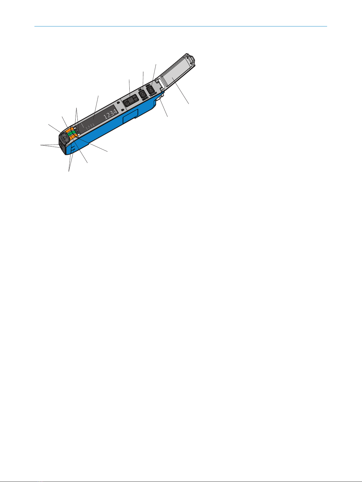
4.2 Device overview........................................................................................ 9
5 Mounting............................................................................................. 10
5.1 Scope of delivery....................................................................................... 10
5.2 Mounting requirements............................................................................ 10
5.3 Connecting fibers...................................................................................... 10
5.4 Mounting/removing the sensor............................................................... 11
5.5 Ambient temperature............................................................................... 12
5.6 Alignment.................................................................................................. 12
6 Electrical installation........................................................................ 13
6.1 Notes on UL approval............................................................................... 13
6.2 Connections.............................................................................................. 14
6.3 Multifunction input/output....................................................................... 15
6.4 Wiring the digital input............................................................................. 15
6.5 Wiring the digital outputs......................................................................... 15
7 Commissioning.................................................................................. 17
7.1 YouTube videos......................................................................................... 17
7.2 Initial menu settings................................................................................. 17
7.3 Setting the sensing range/switching threshold/current or voltage
range/teach-in.......................................................................................... 18
8 Operation............................................................................................ 21
8.1 Control elements...................................................................................... 21
8.2 General sensor functions......................................................................... 22
8.3 Main menu navigation tree (1st menu level).......................................... 24
8.4 Default settings (1st menu level)............................................................ 25
8.5 Display settings......................................................................................... 27
8.6 Time functions.......................................................................................... 30
8.7 Detection parameters............................................................................... 33
8.8 I/O settings............................................................................................... 39
8.9 Device information.................................................................................... 45
8.10 Analog channel settings........................................................................... 47
8.11 Initializing the device................................................................................ 50
CONTENTS
8027947 /2022-12-14 | SICK O P E R A T I N G I N S T R U C T I O N S | WLL80 Analog 3
Subject to change without notice

8.12 Teach-in..................................................................................................... 51
9 Troubleshooting................................................................................. 65
10 Disassembly and disposal............................................................... 69
11 Maintenance...................................................................................... 70
12 Technical data.................................................................................... 71
12.1 Technical specifications........................................................................... 71
12.2 Dimensional drawings.............................................................................. 72
13 Annex.................................................................................................. 73
13.1 Conformities and certificates................................................................... 73
CONTENTS
4O P E R A T I N G I N S T R U C T I O N S | WLL80 Analog 8027947 /2022-12-14 | SICK
Subject to change without notice

1 About this document
1.1 Further information
You can find the product page with further information under the SICK Product ID at:
pid.sick.com/{P/N}.
P/N corresponds to the part number of the product.
The following information is available depending on the product:
•Data sheets
•These publication in all available languages
•CAD files and dimensional drawings
•Certificates (e.g., declaration of conformity)
•Other publications
•Software
•Accessories
1.2 Symbols and document conventions
Warnings and other notes
DANGER
Indicates a situation presenting imminent danger, which will lead to death or serious
injuries if not prevented.
WARNING
Indicates a situation presenting possible danger, which may lead to death or serious
injuries if not prevented.
CAUTION
Indicates a situation presenting possible danger, which may lead to moderate or minor
injuries if not prevented.
NOTICE
Indicates a situation presenting possible danger, which may lead to property damage if
not prevented.
NOTE
Highlights useful tips and recommendations as well as information for efficient and
trouble-free operation.
Instructions to action
bThe arrow denotes instructions to action.
1. The sequence of instructions is numbered.
2. Follow the order in which the numbered instructions are given.
✓The tick denotes the results of an action.
ABOUT THIS DOCUMENT 1
8027947 /2022-12-14 | SICK O P E R A T I N G I N S T R U C T I O N S | WLL80 Analog 5
Subject to change without notice

2 Safety information
■Read these operating instructions before commissioning the device.
■
Connection, mounting and configuration of the device must only be carried out by qualified personnel.
■
2006/42/EC
NO
SAFETY
This device does not constitute a safety component as defined in the Machinery Directive.
■
Do not install the sensor in places exposed to direct UV radiation (sunlight) or other weather conditions
unless this is expressly permitted in the operating instructions.
■When commissioning the device, ensure adequate protection against moisture and contamination.
■These operating instructions contain information required during the life cycle of the photoelectric sensor.
2 SAFETY INFORMATION
6O P E R A T I N G I N S T R U C T I O N S | WLL80 Analog 8027947 /2022-12-14 | SICK
Subject to change without notice

3 Intended use
The WLL80 fiber-optic sensor is an opto-electronic sensor which – in combination with fibers – is used for optical,
non-contact detection of objects.
A fiber-optic sensor is designed for mounting and may only be operated according to its intended function. For this
reason, the fiber-optic sensor is not equipped with direct safety devices.
The system designer must provide measures to ensure the safety of persons and systems in accordance with the
legal guidelines.
SICK AG assumes no liability for losses or damage arising from the use of the product, either directly or indirectly.
This applies in particular to use of the product that does not conform to its intended purpose and is not described
in this documentation.
If the product is used for any other purpose or modified in any way, any warranty claim against SICK AG shall
become void.
INTENDED USE 3
8027947 /2022-12-14 | SICK O P E R A T I N G I N S T R U C T I O N S | WLL80 Analog 7
Subject to change without notice

4 Product description
4.1 Product identification
Type label
D-79183
Waldkirch,
Germany
6076723
21XX0001H
DID8389244
WLL80P-22T6Y1DZA71Z1Z1
BN :1- L+ 12...30V DC, Class 2
BU :3- M 0V
BK :4- Q1/C OUT
WH :2- Q2
Enclosure Type1
MADE IN CHINA
0.1A
<
_
_
OUT 0.1A / MFin
<
1 2
4
5 3 6
Figure 1: Side view of WLL80 with label details
1Pin assignment
2Electrical data and environmental data
3Date of manufacture
4Type code of device
5Part number
62D code
Logos/approvals
Figure 2: Side view of WLL80 with logos
4 PRODUCT DESCRIPTION
8O P E R A T I N G I N S T R U C T I O N S | WLL80 Analog 8027947 /2022-12-14 | SICK
Subject to change without notice

4.2 Device overview
1
2
1
3
4
2
5
6
7
8
9
ß
â
á
Figure 3: Device overview
1Connection
2Hinged cover for the pushbuttons
3Teach-in/escape pushbutton
4Menu/OK pushbutton
5Plus/minus selection pushbuttons
6Display
7Indicator for correctly inserted fibers
8Yellow LED: Status analog channel
9Green LED: Supply voltage active
10 Yellow LED: Status channel 1
11 Fiber optic interlock
12 Fiber optic connection openings
13 Sender/receiver indicator
PRODUCT DESCRIPTION 4
8027947 /2022-12-14 | SICK O P E R A T I N G I N S T R U C T I O N S | WLL80 Analog 9
Subject to change without notice

5 Mounting
5.1 Scope of delivery
•Device in the version ordered (including mounting bracket, if applicable)
•Quick start guide
•Safety notes
The fibers are not included with delivery.
5.2 Mounting requirements
•Typical space requirement for the device, see type-specific dimensional drawing, see "Technical data",
page 71.
•Comply with technical data, such as the permitted ambient conditions for operation of the device (e.g.,
temperature range, EMC interference emissions, ground potential),
•To prevent condensation, avoid exposing the device to rapid changes in temperature.
•Protect the device from direct sunlight.
•shock and vibration-free mounting
5.3 Connecting fibers
4
5
6
1
3
2
Figure 4: Connecting fibers
1. Open the fiber locking mechanism1.
2. Insert the fibers 4 into the openings provided (see receiver and sender symbol on the housing) 2+5as far
as they will go (check the indicator for correctly inserted fibers 6).
3. Close the fiber locking mechanism 3.
NOTICE
When using a fiber optic proximity variant with a coaxial fiber arrangement, connect the single-core optical fiber to
the sender. Connect the multi-core optical fiber (fiber bundle) to the receiver.
5 MOUNTING
10 O P E R A T I N G I N S T R U C T I O N S | WLL80 Analog 8027947 /2022-12-14 | SICK
Subject to change without notice

5.3.1 Use fibers with thin end sleeves
1
2
3
Figure 5: Fiber with thin end sleeve
1Fiber with thin end sleeve
2Separation position
3Adjustment cap
1. Turn the adjustment cap 3fully counterclockwise. Insert the optical fiber 1.
2. Turn the adjustment cap 3 clockwise to lock it.
3. Cut off any excess optical fiber.
5.4 Mounting/removing the sensor
Mounting
1
2
Figure 6: Mount the WLL80 on the DIN rail
1. Hook the lug of the sensor into the DIN rail/mounting bracket
2. Press the sensor in the direction of arrow 2 until the spring clip locks onto the DIN rail/mounting bracket.
Removing
1
2
Figure 7: Remove the WLL80 from the DIN rail
MOUNTING 5
8027947 /2022-12-14 | SICK O P E R A T I N G I N S T R U C T I O N S | WLL80 Analog 11
Subject to change without notice

1. Push the sensor in direction of the arrow 1
2. On the side where the fibers are connected, lift the sensor in the direction of the arrow 2 and remove it.
5.5 Ambient temperature
Max. output current: 20mA.
Ambient temperature during operation:
-25°C ... +55°C1
-13°F ... +131°F1
1Air humidity: 35 ... 85%
5.6 Alignment
When using the WLL80 fiber-optic sensor with through-beam fibers, align the sender fibers with the receiving
fibers. Select the position so that the emitted light beam hits the receiver. Tip: Use white paper or a reflector as an
alignment aid. The sender must have a clear view of the receiver. There must be no object in the path of the beam
[see figure 8]. You must ensure that the optical openings (fiber surfaces) of the fibers are completely clear.
Figure 8: Alignment of through-beam fibers
When using the WLL80 fiber-optic sensor with a proximity fiber, align the fiber to the object. Select the position
so that the emitted light beam hits the center of the object. You must ensure that the optical openings (fiber
surfaces) of the fibers are completely clear [see figure 9].
Figure 9: Alignment of proximity fiber
5 MOUNTING
12 O P E R A T I N G I N S T R U C T I O N S | WLL80 Analog 8027947 /2022-12-14 | SICK
Subject to change without notice

6 Electrical installation
The sensors must be connected in a voltage-free state. The following information must be observed, depending on
the connection type:
– Male connector connection: Pin assignment
– Cable: Wire color
Only apply voltage and switch on the voltage supply once all electrical connections have been established.
Explanation of the connection terminology used in the following tables:
BN = brown
WH = white
BU = blue
BK = black
GY = gray
n.c. = not connected
MFIO = multifunctional input/output
MFIn= multifunctional input
MFOut = multifunctional output
Q1 = channel1 output signal
Q2 = Analog channel
L+ = supply voltage (UV)
M = ground
6.1 Notes on UL approval
6.1.1 UL Satisfaction Ratings Listed
The total output current and ambient temperature will be restricted as follows depends
on the number of the sensors.
E300503
No control output setting 1 control output setting
Stand-alone analog model:
Input: 12 - 24Vdc, Class 2, Max. 0.126A
Analog current output: Max. 0.024A
Analog voltage output: Max. 10V
Maximum Ambient Temperature: +55°C
Stand-alone analog model:
Input: 12 - 24Vdc, Class 2, Max. 0.126A
Output: 12 - 30Vdc, Class 2, Max. 0.05A
Analog current output: Max. 0.024A
Analog voltage output: Max. 10V
Maximum Ambient Temperature: +55°C
Environmental
Enclosure Tye Rating: Type 1
ELECTRICAL INSTALLATION 6
8027947 /2022-12-14 | SICK O P E R A T I N G I N S T R U C T I O N S | WLL80 Analog 13
Subject to change without notice

6.2 Connections
UB: 12 ... 30VDC
see "Technical data", page 71
Table 1: Pin assignment
WLL80x- x2xHxxxxxxxxxxx xIxIxxxxxxxxxxx
1 = BN + (L+) + (L+)
2 = WH MFIO
(Default: Q1)
MFIn
(Default: Teach-in)
3 = BU - (M) - (M)
4 = BK Analog out Analog out/analog GND
5 = GY - Q1
M8, 4-pin
4
3
2
1
E300503
Cable, 5-wire
Connection diagram:
BN
BK
GY
WH
BU
12 ... 24 VDC
0V
Load /
Last
Load /
Last
Analog Input Device /
Analoger Eingang Gerät
Control Output /
Ausgang Steuerung
External input /
Externer Eingang
3
4
Figure 10: PNP setting or push-pull
1When I/O polarity is set to Push-pull and the sensor is connected with plus common circuits.
2When I/O polarity is set to Push-pull or PNP and the sensor is connected with minus direct current circuits.
6 ELECTRICAL INSTALLATION
14 O P E R A T I N G I N S T R U C T I O N S | WLL80 Analog 8027947 /2022-12-14 | SICK
Subject to change without notice

BN
BK
GY
WH
BU
12 ... 24 VDC
0V
Load /
Last
Analog Input Device /
Analoger Eingang Gerät
Control Output /
Ausgang Steuerung
External input /
Externer Eingang
Figure 11: NPN setting
6.3 Multifunction input/output
The MF multifunction input/output can optionally be deactivated, or configured as an input or output.
MFIO/MFIn input functions:
•Teach-in
•Switching off the send LED (test)
•Reset counter value
•Reset extreme value memory
MFIO/MFOut output functions:
•Operational safety alarm (Quality of Run Alarm)
•Digital output channel 1
•Response signal for successfully performed teach-in(feedback)
•Error mode for signal when the measured value is outside the set range.
6.4 Wiring the digital input
The digital input can be used to start a teach-in, to switch off the sender as a test input, for an external input
signal (Smart Task), or to reset the counter value (Smart Task). Voltage level at the input starts the corresponding
function of the sensor.
Table 2: Electrical values
Signal voltage HIGH VCC: 24V 13.5V
VCC: 12V 9.0V
Signal voltage LOW VCC: 24V 8.0V
VCC: 23V 4.0V
Input impedance 100kΩ
6.5 Wiring the digital outputs
The number of digital inputs available at the connections will vary depending on the sensor, see "Connections",
page 14. If the allocated event occurs in the read process, then the corresponding digital output is live.
In each case, the digital outputs are short-circuit protected and overcurrent protected. The switching behavior is
selectable: push-pull, PNP or NPN (open collector).
Electrical values:
ELECTRICAL INSTALLATION 6
8027947 /2022-12-14 | SICK O P E R A T I N G I N S T R U C T I O N S | WLL80 Analog 15
Subject to change without notice

•The output current (100mA) per sensor is identical for all digital outputs.
•PNP/NPN residual voltage ≤1.8V
•Dielectric strength max 30V
•Output impedance 10 Ω
NOTE
When using sensors in bus mode, the output current per sensor is reduced as follows:
•From 2 sensors = max. 20mA
6 ELECTRICAL INSTALLATION
16 O P E R A T I N G I N S T R U C T I O N S | WLL80 Analog 8027947 /2022-12-14 | SICK
Subject to change without notice

7 Commissioning
7.1 YouTube videos
The individual steps for commissioning are also shown in videos:
Table 3: Video overview
Commissioning and initial menu settings
https://youtu.be/lbny_4aauYQ
Analog channel basic settings
https://youtu.be/gQCba58PzGE
Teach-in
https://youtu.be/e75xsxQ8rd8
Counter function
https://www.youtube.com/watch?
v=Jp_adG29ha0
7.2 Initial menu settings
Some initial settings need to be configured (during initial commissioning or after an initialization) to make the
sensor ready for operation. These defaults specify the parameters required for operating the device. It is often the
case that only these parameters need to be set in order to use the device.
Table 4: Initial menu setting
1
A|English
1/2
OK ESC
Display language
Select language using and confirm using OK.
1
A|
1/2 English
English: English
1
A|
1/2 Deutsch
Deutsch: German
1
A|
1/2 日本語
日本語 : Japanese
1
A|
1/2 中文
中文 : Chinese
1
A|
1/2 한국어
한국어 : Korean
1
A|4-20 mA
2/2
OK ESC
Analog output
Select analog output using and confirm using OK.
1
A|
2/2 4-20mA
Analog output current based
4-20mA
1
A|
2/2 0-10V
Analog output voltage based
0-10V
1
A|
2/2 1-5V
Analog output voltage based
1-5V
COMMISSIONING 7
8027947 /2022-12-14 | SICK O P E R A T I N G I N S T R U C T I O N S | WLL80 Analog 17
Subject to change without notice

1
A|To run mode
The device is now in Run mode and ready to use.
1
A|1234
9999
0
Top left value: Upper threshold (digits) of the current or voltage range
(assignment of the displayed value to the current or voltage value
20mA/10V/5V)
Bottom left value: Lower threshold (digits) of the current or voltage
range (assignment of the displayed value to the current or voltage value
4mA/0V/1V)
Right value: Current received light value (digits)
NOTE
The initial menu settings are also shown in a video:
7.3 Setting the sensing range/switching threshold/current or voltage range/teach-in
Setting the sensing range or defining the switching point or assigning received light values (digits) to the current or
voltage range can be done manually or using various teach-in modes that can be selected in the teach-in menu.
7.3.1 Binary switching channel Q1
Manual setting the switching points:
The switching point or switchings points can be set manually.
Table 5: Manually setting the switching points
1
A
|1000
100
ESC
Run mode
1
A
|1000
100
OK
Adjustment with
1
A
|1000
200
Run mode
Manually setting the switching point/switching points
Activate manual setting of the switching point using (switching
point flashes). Adjust the switching point using (increase) and
(decrease).
In modes (zone teach-in, window teach-in) with two switching points – SP1
and SP2 – after confirming SP1 using OK, the display changes to the
setting of SP2. Adjust SP2 also using . Confirm using .
After confirmation (or after 30seconds without button operation), the
display returns to run mode.
2-point teach-in:
The 2-point teach-in sets the switching point SP1 to the average value between the received light values of two
teach-in points TP1 and TP2. You can teach in the teach-in point with object or without object first.
7 COMMISSIONING
18 O P E R A T I N G I N S T R U C T I O N S | WLL80 Analog 8027947 /2022-12-14 | SICK
Subject to change without notice

Table 6: 2-point teach-in
Run mode
1
A
|1000
100
TEACH
1 sec.
Run mode
1
A|6000
2.Pt
OK
1
A
|Update
3500
1
A
|To run mode
1
A
|1000
3500
Run mode
Perform a fast two-point teach-in by pressing and holding (1second) TEACH
(confirmation of teach-in point TP1) and then by holding down (1second)
TEACH (confirmation of teach-in point TP2).
The switching point (SP) is updated according to the taught-in teach-in points
(TP1, TP2) and the display returns to run mode.
Pushbuttons Through-beam Energy consideration
Step 1 with object
TP1
without object
TP1
SP
Energy
Time
50%
SP = (TP1 + TP2) x 50%
TP2 50%
Step 2 without object/on back‐
ground
TP1
SP
TP2 50% 50%
with object
TP1
SP
Energy
Time
50%
SP = (TP1 + TP2) x 50%
TP2 50%
7.3.2 Analog channel QA
Manually setting the current or voltage range:
Table 7: Manually setting the current or voltage range
1234
ESC
1
A|9999
0
Manually setting the current or voltage range
Activate manual assignment of the received light values (digits) to the cur‐
rent or voltage values using (received light value for assignment to the
upper threshold (UT) of the current or voltage range 20mA/10V/5V
flashes).
1234
ESCOK
1
A|9999
0
-----------------------------------------
Adaption with
Adjust the upper threshold (UT) using (increase) and (decrease).
Click to confirm. After confirmation, the received light value for
assignment to the lower threshold (LT) of the current or voltage range
4mA/0V/1V flashes. Adjust the lower threshold (LT) using
(increase) and (decrease). Click to confirm.
1234
OK
1
A|1111
0
-----------------------------------------
Adaption with
After confirmation (or 30seconds without button operation), the display
returns to run mode.
COMMISSIONING 7
8027947 /2022-12-14 | SICK O P E R A T I N G I N S T R U C T I O N S | WLL80 Analog 19
Subject to change without notice

1234
1
A|1111
22
Run mode
Analog two-point teach-in:
The analog two-point teach-in assigns the higher received light value of the teach-in points TP1 and TP2 to
the upper threshold (UT) of the current or voltage range (20mA/10V/5V). The lower received light value
of the teach-in points TP1 and TP2 is assigned to the lower threshold (LT) of the current or voltage range
(4mA/0V/1V). Either the teach-in point with the lower received light value or the teach-in point with the higher
received light value can be taught in first.
Table 8: Analog two-point teach-in
Run mode
1234
ESC
TEACH
1 sec.
-----------------------------------------
1
A|9999
0
5678
TEACH
1 sec.
-----------------------------------------
1
A|2. Pt
1
A|Update
5678
1234
1
A|To run mode
1
A|1234
5678
1234
Perform a fast two-point teach-in by pressing and holding (1second) TEACH
(confirmation of teach-in point TP1) and then by holding down (1second)
TEACH (confirmation of teach-in point TP2).
The switching point (SP) is updated according to the taught-in teach-in points
(TP1, TP2) and the display returns to run mode.
Pushbuttons Through-beam Energy consideration
Step 1 With object position 1
(higher received light)
TP1
TP1 = Upper threshold
(20mA/10V/5V)
With (transparent) object
with (high) transmission
1 or without object
(higher received light
value)
1
2
TP1
OS
US
TP2
Step 2 With object position 2
or without object (lower
received light value)
TP1 TP2
TP2 = Lower threshold
(4mA/0V/1V)
With (transparent) object
with (low) transmission
2 (lower received light
value)
1
2
TP1
OS
US
TP2
UT Upper threshold
LT Lower threshold
1Current/voltage value [mA/V]
2Received light [digits]
7 COMMISSIONING
20 O P E R A T I N G I N S T R U C T I O N S | WLL80 Analog 8027947 /2022-12-14 | SICK
Subject to change without notice
Other manuals for WLL80 Analog
2
Table of contents
Other SICK Accessories manuals

SICK
SICK WLA12L User manual

SICK
SICK WLL80 Analog User manual

SICK
SICK MLS User manual

SICK
SICK EDS35-2 Series User manual

SICK
SICK WT18-3 User manual

SICK
SICK WSO26 A0 Series User manual

SICK
SICK LRS4000 User manual

SICK
SICK MRS1000 User manual

SICK
SICK WL24-2 Series User manual

SICK
SICK RFU62 Series User manual