SICK MPS-M User manual

OPERATING INSTRUCTIONS
MPS-M
Position sensor

Described product
MPS-M
Manufacturer
SICK AG
Erwin-Sick-Str. 1
79183 Waldkirch
Germany
Legal information
This work is protected by copyright. Any rights derived from the copyright shall be
reserved for SICK AG. Reproduction of this document or parts of this document is
only permissible within the limits of the legal determination of Copyright Law. Any modi‐
fication, abridgment or translation of this document is prohibited without the express
written permission of SICK AG.
The trademarks stated in this document are the property of their respective owner.
© SICK AG. All rights reserved.
Original document
This document is an original document of SICK AG.
2O P E R A T I N G I N S T R U C T I O N S | MPS-M 8028183/2022-12-30 | SICK
Subject to change without notice

Contents
1 About this document........................................................................ 5
1.1 Information on the operating instructions.............................................. 5
1.2 Further information................................................................................... 5
1.3 Symbols and document conventions...................................................... 5
2 Safety information............................................................................ 7
2.1 Intended use............................................................................................. 7
2.2 Improper use............................................................................................. 7
2.3 Limitation of liability................................................................................. 7
2.4 Requirements for skilled persons and operating personnel.................. 7
2.5 Hazard warnings and operational safety................................................. 8
3 Product description........................................................................... 9
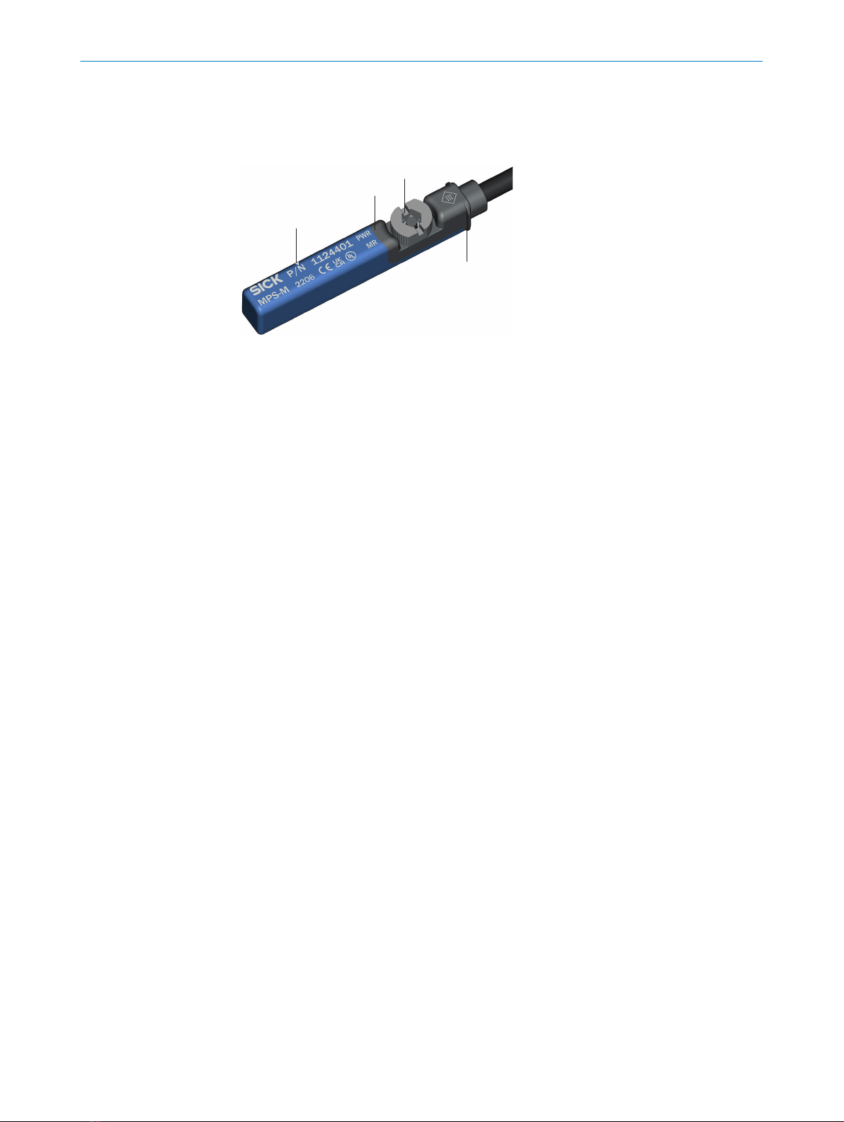
3.1 Device view................................................................................................ 9
3.2 Product characteristics............................................................................ 9
3.2.1 Product features...................................................................... 9
3.3 Operating principle................................................................................... 9
3.3.1 Principle of operation.............................................................. 9
3.3.2 Detection range....................................................................... 10
3.3.3 Position output......................................................................... 10
3.4 Operating and status indicators.............................................................. 12
3.4.1 Status indicators...................................................................... 12
4 Transport and storage....................................................................... 13
4.1 Transport................................................................................................... 13
4.2 Transport inspection................................................................................. 13
4.3 Storage...................................................................................................... 13
5 Mounting............................................................................................. 14
5.1 Mounting requirements............................................................................ 14
5.2 Mounting................................................................................................... 14
6 Electrical installation........................................................................ 15
6.1 Safety......................................................................................................... 15
6.1.1 Notes on electrical installation............................................... 15
6.1.2 Wiring instructions................................................................... 15
6.2 Connections.............................................................................................. 17
6.2.1 Pin assignment/Connection diagram + wire colors.............. 17
6.3 Connecting the supply voltage................................................................. 17
7 Commissioning.................................................................................. 18
7.1 Overview of commissioning steps........................................................... 18
7.2 Positioning on drive.................................................................................. 18
7.3 Put the sensor into operation for the first time...................................... 18
CONTENTS
8028183/2022-12-30 | SICK O P E R A T I N G I N S T R U C T I O N S | MPS-M 3
Subject to change without notice

8 Operation............................................................................................ 20
8.1 General notes on operation..................................................................... 20
8.2 Operation via IO-Link................................................................................ 20
8.2.1 Process data structure............................................................ 20
8.2.2 General functions.................................................................... 20
8.2.3 Configuration options via IO-Link............................................ 21
8.2.4 Actuator diagnostic functions................................................. 27
9 Troubleshooting................................................................................. 30
10 Maintenance...................................................................................... 31
11 Decommissioning............................................................................. 32
11.1 Replace device.......................................................................................... 32
11.2 Disassembly and disposal....................................................................... 32
11.3 Returning devices..................................................................................... 32
12 Technical data.................................................................................... 33
12.1 Dimensional drawing................................................................................ 34
13 Glossary.............................................................................................. 36
14 Annex.................................................................................................. 37
14.1 Conformities and certificates................................................................... 37
CONTENTS
4O P E R A T I N G I N S T R U C T I O N S | MPS-M 8028183/2022-12-30 | SICK
Subject to change without notice

1 About this document
1.1 Information on the operating instructions
These operating instructions provide important information on how to use sensors from
SICK AG.
Prerequisites for safe work are:
•Compliance with all safety notes and handling instructions supplied.
•Compliance with local work safety regulations and general safety regulations for
sensor applications.
The operating instructions are intended to be used by qualified personnel and electrical
specialists.
NOTE
Read these operating instructions carefully before starting any work on the sensor, in
order to familiarize yourself with the sensor and its functions.
The instructions constitute an integral part of the product and are to be stored in the
immediate vicinity of the sensor so they remain accessible to staff at all times. If the
sensor is passed on to a third party, these operating instructions should be handed
over with it.
These operating instructions do not provide information on operating the machine
in which the sensor is integrated. For information about this, refer to the operating
instructions of the particular machine.
1.2 Further information
You can find the product page with further information under the SICK Product ID at:
pid.sick.com/{P/N}.
P/N corresponds to the part number of the product.
The following information is available depending on the product:
•Data sheets
•These publication in all available languages
•CAD files and dimensional drawings
•Certificates (e.g., declaration of conformity)
•Other publications
•Software
•Accessories
1.3 Symbols and document conventions
Warnings and other notes
DANGER
Indicates a situation presenting imminent danger, which will lead to death or serious
injuries if not prevented.
WARNING
Indicates a situation presenting possible danger, which may lead to death or serious
injuries if not prevented.
ABOUT THIS DOCUMENT 1
8028183/2022-12-30 | SICK O P E R A T I N G I N S T R U C T I O N S | MPS-M 5
Subject to change without notice

CAUTION
Indicates a situation presenting possible danger, which may lead to moderate or minor
injuries if not prevented.
NOTICE
Indicates a situation presenting possible danger, which may lead to property damage if
not prevented.
NOTE
Highlights useful tips and recommendations as well as information for efficient and
trouble-free operation.
Instructions to action
►The arrow denotes instructions to action.
1. The sequence of instructions is numbered.
2. Follow the order in which the numbered instructions are given.
✓The tick denotes the results of an action.
1 ABOUT THIS DOCUMENT
6O P E R A T I N G I N S T R U C T I O N S | MPS-M 8028183/2022-12-30 | SICK
Subject to change without notice

2 Safety information
2.1 Intended use
The sensor from the MPS-M product family is an intelligent, magnetic position sensor.
It is used for non-contact detection of the piston stroke of pneumatic drives with axially
magnetized permanent magnets.
SICK AG assumes no liability for losses or damage arising from the use of the product,
either directly or indirectly. This applies in particular to use of the product that does not
conform to its intended purpose and is not described in this documentation.
2.2 Improper use
•The sensor does not constitute a safety-relevant device according to the EC Machi‐
nery Directive (2006/42/EC).
•The sensor must not be used in explosion-hazardous areas.
•Any other use that is not described as intended use is prohibited.
•Any use of accessories not specifically approved by SICK AG is at your own risk.
•The sensor is not suitable for outdoor applications.
NOTICE
Danger due to improper use!
Any improper use can result in dangerous situations.
Therefore, take note of the following information:
►The sensor should be used only in line with intended use specifications.
►All information in these operating instructions must be strictly complied with.
2.3 Limitation of liability
Applicable standards and regulations, the latest state of technological development,
and our many years of knowledge and experience have all been taken into account
when assembling the data and information contained in these operating instructions.
The manufacturer accepts no liability for damage caused by:
■Failing to observe the operating instructions
■Improper use
■Use by untrained personnel
■Unauthorized conversions
■Technical modifications
■Use of unauthorized spare parts, consumables, and accessories
With special variants, where optional extras have been ordered, or owing to the latest
technical changes, the actual scope of delivery may vary from the features and illustra‐
tions shown here.
2.4 Requirements for skilled persons and operating personnel
WARNING
Risk of injury due to insufficient training.
Improper handling of the sensor may result in considerable personal injury and material
damage.
■All work must only ever be carried out by the stipulated persons.
SAFETY INFORMATION 2
8028183/2022-12-30 | SICK O P E R A T I N G I N S T R U C T I O N S | MPS-M 7
Subject to change without notice

The operating instructions state the following qualification requirements for the various
areas of work:
■Instructed personnel have been briefed by the operating entity about the tasks
assigned to them and about potential dangers arising from improper action.
■Skilled personnel have the specialist training, skills, and experience, as well as
knowledge of the relevant regulations, to be able to perform tasks assigned to
them and to detect and avoid any potential dangers independently.
■Electricians have the specialist training, skills, and experience, as well as knowl‐
edge of the relevant standards and provisions to be able to carry out work on
electrical systems and to detect and avoid any potential dangers independently. In
Germany, electricians must meet the specifications of the BGVA3 Work Safety
Regulations (e.g.,Master Electrician). Other relevant regulations applicable in
other countries must be observed.
The following qualifications are required for various activities:
Activities Qualification
Mounting, maintenance ■Basic practical technical training
■Knowledge of the current safety regulations in the workplace
Electrical installation,
device replacement
■Practical electrical training
■Knowledge of current electrical safety regulations
■Knowledge of the operation and control of the devices in their
particular application
Commissioning, configura‐
tion
■Basic knowledge of the design and setup of the described
connections and interfaces
■Basic knowledge of data transmission
■Knowledge of the operation and control of the devices in their
particular application
Operation of the devices in
their particular application
■Knowledge of the operation and control of the devices in their
particular application
■Knowledge of the software and hardware environment in the
application
2.5 Hazard warnings and operational safety
Please observe the safety notes and the warnings listed here and in other chapters
of these operating instructions to reduce the possibility of risks to health and avoid
dangerous situations.
2 SAFETY INFORMATION
8O P E R A T I N G I N S T R U C T I O N S | MPS-M 8028183/2022-12-30 | SICK
Subject to change without notice

3 Product description
3.1 Device view
1
2
3
4
Figure 1: Operating elements and status indicators
1Fixing screw, size 2.5
22 x LED(PWR (green) = Voltage supply, MR (yellow) = measuring range)
3Physical zero position
4Retaining ribs
3.2 Product characteristics
3.2.1 Product features
The MPS-M is used as a position sensor for non-contact linear position measurement
mainly on pneumatic cylinders, grippers, and slides. When using IO-Link, up to 8 switch‐
ing points can also be set and additional actuator diagnostic data can be recorded and
output:
•Stroke traveled
•Cycle time
•Dwell time of the piston
•Travel time of the piston
•Average piston velocity
•Current measured field strength
•Maximum measured field strength
•Cycle count
•Total distance traveled by the piston
•Operating hours
•Power-on / power-off cycles
A description of the diagnostic functions can be found in section 8.2.4.
Target applications
•Analog position measurement for short stroke in systems without IO-Link
•Position measurement for short stroke in systems with IO-Link
•Detection of 8 positions via 8 switching points with IO-Link
3.3 Operating principle
3.3.1 Principle of operation
The MPS-M determines the position of an encoder magnet via a row of 2 sensor
elements located in the sensor head.
PRODUCT DESCRIPTION 3
8028183/2022-12-30 | SICK O P E R A T I N G I N S T R U C T I O N S | MPS-M 9
Subject to change without notice

Axially and diametrically magnetized magnets can be detected since the two sensor
elements measure the field strength in both the X- and Y-direction.
y y
xx
y y
xx
1
2
3
1
2
4
m
m
y (radial)
x (axial)
1Sensor element 1
2Sensor element 2
3Axially magnetized magnet
4Diametrically magnetized magnet
3.3.2 Detection range
The sensor is designed for a detection range of 50mm. The zero point / physical zero
position is marked with a triangle on the sensor head. The distance from the zero point
to the cable is -25mm, and to the top of the sensor head is +25mm.
50
32,5
0
- 25+ 25
1
2
3
Figure 2: Detection range
1Detection range
2Housing length
3Zero point / physical zero position
3.3.3 Position output
The sensor can output a linearized position in a detection range of approx. 50mm
(depends on the drive).
•Via IO-Link, the detection range of 50mm (-25mm ... 25mm) corresponds to
5,000digits (-2,500digits...2,500digits). I.e., 1 digit corresponds to 10µm. When
leaving the detection range, the value 32,760 or -32,760 digits1) is displayed. If
the field strength is no longer sufficient, 32,764 is output as per the Smart Sensor
profile.
•Via the analog output, the detection range of 50mm (-25mm ... 25mm) corre‐
sponds to the analog output values of 0-10V. When leaving the measuring range,
11V or 10.5V are output.
3 PRODUCT DESCRIPTION
10 O P E R A T I N G I N S T R U C T I O N S | MPS-M 8028183/2022-12-30 | SICK
Subject to change without notice

NOTE
The Out-of-Range display via the analog output or via IO-Link is always active. It is not
possible to manually deactivate/activate the Out-of-Range display.
0
10.5 V
10 V
11 V
0 V
1
32
4
5
6
Figure 3: Zero point / physical zero position for analog output
0
-32760
32760
1
3
2
4
5
6
Figure 4: Zero point / physical zero position for IO-Link output
1Zero point / physical zero position
2Positive positions
3Negative positions
4Sensor detection range:
0 ... 10V (analog output)
2,500 ... -2,500 digits (IO-Link output)
5Piston position
6Sensor position output
PRODUCT DESCRIPTION 3
8028183/2022-12-30 | SICK O P E R A T I N G I N S T R U C T I O N S | MPS-M 11
Subject to change without notice

3.4 Operating and status indicators
3.4.1 Status indicators
There are 2 LEDs on the sensor. The Power LED lights up green and the measuring
range LED yellow.
The table below describes the individual function displays.
Table 1: Function of the LEDs
Sensor condition LED 1 (MR) (yellow) LED 2 (PWR) (green)
Display Meaning Display Meaning
SIO
O
Lights up
Magnet inside
the measuring
range O
Lights up Power ok
o
Does not light up
Magnet outside
the measuring
range
IO-Link no function1F
Flashing IO-Link active
Error No error display via LEDs
1During position measurement via IO-Link, only LED2 (PWR) flashes
3 PRODUCT DESCRIPTION
12 O P E R A T I N G I N S T R U C T I O N S | MPS-M 8028183/2022-12-30 | SICK
Subject to change without notice

4 Transport and storage
4.1 Transport
For your own safety, please read and observe the following notes:
NOTE
Damage to the sensor due to improper transport.
■The device must be packaged for transport with protection against shock and
damp.
■Transport should be performed by specialist staff only.
■The utmost care and attention is required at all times during unloading and
transportation on company premises.
■Note the symbols on the packaging.
■Do not remove packaging until immediately before you start mounting.
4.2 Transport inspection
Immediately upon receipt at the receiving work station, check the delivery for complete‐
ness and for any damage that may have occurred in transit. In the case of transit
damage that is visible externally, proceed as follows:
■Do not accept the delivery or only do so conditionally.
■Note the scope of damage on the transport documents or on the transport compa‐
ny’s delivery note.
■File a complaint.
NOTE
Complaints regarding defects should be filed as soon as these are detected. Damage
claims are only valid before the applicable complaint deadlines.
4.3 Storage
Store the device under the following conditions:
■Recommendation: Use the original packaging.
■Do not store outdoors.
■Store in a dry area that is protected from dust.
■To allow any residual dampness to evaporate, do not package in airtight contain‐
ers.
■Do not expose to any aggressive substances.
■Protect from sunlight.
■Avoid mechanical shocks.
■Storage temperature: see "Technical data", page 33.
■Relative humidity: see "Technical data", page 33.
TRANSPORT AND STORAGE 4
8028183/2022-12-30 | SICK O P E R A T I N G I N S T R U C T I O N S | MPS-M 13
Subject to change without notice

5 Mounting
5.1 Mounting requirements
■Comply with technical parameters such as the permitted ambient conditions for
the operation of the sensor (e.g., temperature range, EM interference), see "Tech‐
nical data", page 33.
■Protect the sensor from direct sunlight.
■Only mount sensor with the intended accessories.
Mounting location
When selecting the mounting location, the following factors must be considered:
■The mounting location must be as free from (electro)magnetic disturbance fields
as possible
5.2 Mounting
Insert sensor into the slot from above. The PWR LED1) lights up green.
1
4
3
2
Figure 5: Installation steps
1Insert sensor
2Tighten screw
3Tightening torque typ. 0.7Nm
4AF 2.5
NOTE
When tightening the screw, use a non-magnetic Allen key.
1) PWR LED = Power LED
5 MOUNTING
14 O P E R A T I N G I N S T R U C T I O N S | MPS-M 8028183/2022-12-30 | SICK
Subject to change without notice

6 Electrical installation
6.1 Safety
6.1.1 Notes on electrical installation
CAUTION
Danger due to incorrect supply voltage!
An incorrect supply voltage may result in injuries from electric shocks and/or damage to
the device.
■Only operate the sensor with safety/protective extra-low voltage (SELV/PELV).
NOTICE
Sensor damage or unpredictable operation due to working with live parts.
Working with live parts may result in unpredictable operation.
■Only carry out wiring work when the power is off.
■Only connect and disconnect electrical connections when the power is off.
■The electrical installation must only be performed by electrically qualified person‐
nel.
■Standard safety requirements must be observed when working on electrical
systems!
■Only switch on the supply voltage for the device when the connection tasks have
been completed and the wiring has been thoroughly checked.
■When using extension cables with open ends, ensure that bare wire ends do not
come into contact with each other (risk of short-circuit when supply voltage is
switched on!). Wires must be appropriately insulated from each other.
■Wire cross-sections in the supply cable from the user’s power system must be
designed in accordance with the applicable standards. When this is being done in
Germany, observe the following standards: DIN VDE 0100 (Part 430) and DIN VDE
0298 (Part 4) and/or DIN VDE 0891 (Part 1).
■Circuits connected to the device must be designed as SELV circuits (SELV = Safety
Extra Low Voltage).
■Protect the device with a separate fuse at the start of the supply circuit.
The IP enclosure rating for the sensor is only achieved if the connected cable is
completely screwed in.
6.1.2 Wiring instructions
NOTE
Pre-assembled cables can be found online at:
►www.sick.com/mps-m
Please observe the following wiring instructions:
■During installation, pay attention to the different cable groups. The cables are
grouped into the following four groups according to their sensitivity to interference
or radiated emissions:
°Group 1: Cables very sensitive to interference, such as analog measuring
cables
°Group 2: Cables sensitive to interference, such as sensor cables, communi‐
cation signals, bus signals
ELECTRICAL INSTALLATION 6
8028183/2022-12-30 | SICK O P E R A T I N G I N S T R U C T I O N S | MPS-M 15
Subject to change without notice

°Group 3: Cables which are a source of interference, such as control cables
for inductive loads, motor brakes
°Group 4: Cables which are powerful sources of interference, such as out‐
put cables from frequency inverters, welding system power supplies, power
cables
►Cables in groups 1, 2 and 3, 4 must be crossed at right angles, see figure 6.
►Cables in groups 1, 2 and 3, 4 must be routed in different cable ducts or
metallic separators must be used, see figure 7 and see figure 8. This applies
particularly where cables of devices with a high level of radiated emission,
such asfrequency converters, are laid parallel to sensor cables.
1
2
4
3
1
2
4
3
90
90
Figure 6: Cross cables at right angles
1
2
3
4
Figure 7: Ideal laying – Place cables in different cable ducts
1
23
4
Figure 8: Alternative laying – Separate cables with metallic separators
NOTE
Prevent equipotential bonding currents via the cable shield with a suitable earthing
method, see "Safety", page 15.
6 ELECTRICAL INSTALLATION
16 O P E R A T I N G I N S T R U C T I O N S | MPS-M 8028183/2022-12-30 | SICK
Subject to change without notice

6.2 Connections
6.2.1 Pin assignment/Connection diagram + wire colors
Table 2: Wire assignment for flying leads, 4-wire
Pin Connection Pin assignment
1 BN + (L+)
2 WH UOUT
3 BU - (M)
4 BK IO-Link
0.08mm2
AWG 28
Table 3: Pin assignment for male connector, M8, A-coded, 4-pin
Pin Connection Pin assignment
1 BN + (L+)
2 WH UOUT
3 BU - (M)
4 BK IO-Link
4
3
2
1
Table 4: Pin assignment for male connector, M12, A-coded, 4-pin
Pin Connection Pin assignment
1 BN + (L+)
2 WH UOUT
3 BU - (M)
4 BK IO-Link
2 1
4
3
6.3 Connecting the supply voltage
The sensor must be connected to a voltage supply with the following properties:
•Supply voltage DC 13V ... 30V (SELV/PELV as per currently valid standards)
•Power source with at least 5W power
Protecting the supply cables
To ensure protection against short-circuits/overload in the customer’s supply cables,
the wire cross-sections used must be appropriately selected and protected.
The following standards must be observed in Germany:
•DIN VDE 0100 (part 430)
•DIN VDE 0298 (part 4) and/or DIN VDE 0891 (part 1)
ELECTRICAL INSTALLATION 6
8028183/2022-12-30 | SICK O P E R A T I N G I N S T R U C T I O N S | MPS-M 17
Subject to change without notice

7 Commissioning
7.1 Overview of commissioning steps
■Connect the voltage supply.
■Commission the sensor using the factory settings.
■Configure the sensor.
7.2 Positioning on drive
To achieve the best possible performance, the sensor should be positioned centrally to
the travel range of the magnet. The printed triangle on the sensor indicates the location
of the physical zero position.
1
2
Figure 9: Positioning on drive
1Physical zero position
2Same distance in both directions
7.3 Put the sensor into operation for the first time
The sensor can optionally be operated with or without IO-Link.
If the sensor is operated via IO-Link, an associated IODD file with the appropriate
version must be used. The IODD file can be downloaded at www.sick.com/mps-m. The
production date in the IODD file name must match the production date on the sensor or
packaging.
Teach-in procedure
For optimal sensor performance, move the drive through the entire range of movement
of the drive roughly 5x. Not until teach-in is complete is the complete accuracy (minimal
linearity error, correct display of measuring range) achieved. If switching points are
taught before teach-in is complete, these change their position during the teach-in
process. The teach-in process can be accelerated by running an Application Reset or
Factory Reset or Reset Trained Algorithm Parameter via IO-Link after mounting the sensor. The
sensor then only needs about two strokes to teach in the drive with sufficient accuracy.
A detailed description of the Application Reset can be found in section 8.2.3.1.
Application measuring range
Monotonicity violations can occur in the edge region of drives, which in turn lead to
pseudo-position detections in the edge region. To prevent this, the maximum possible
measuring range of the application (drive) is determined by the sensor. The criterion
for the limits of the application measuring range is the repeatability determined by the
sensor.
The application measuring range can be read via IO-Link using index 16512 (0x4080)
MDC Descr, subindex 1 (0x01) Lower limit and subindex 2 (0x02) Upper limit. The appli‐
cation measuring range can be influenced via the index 265 Position noise limit for
application range [mm]:
7 COMMISSIONING
18 O P E R A T I N G I N S T R U C T I O N S | MPS-M 8028183/2022-12-30 | SICK
Subject to change without notice

Smaller value → Smaller application measuring range, better performance
Larger value → Larger application measuring range, poorer performance
By default, the sensor maps a measuring range of 50mm (from -25mm to +25mm).
Analog measuring range scaling
The analog measuring range can be scaled to suit the stroke via index 207 (0xCF)
Set up analog output. By default, the position -25mm (-2,500digits) corresponds to
0V and the position +25mm (2,500 digits) corresponds to 10V. The analog voltage
value range can be scaled for strokes shorter than 50mm via the subindices 1 (0x01)
Measurement area start point and 2 (0x02) Measurement area end point . This enables the
entire analog value range from 0 to 10V to be output even for strokes shorter than
50mm. To do so, the desired start and end point must be entered in digits (1digit =
10µm) in the corresponding subindex.
COMMISSIONING 7
8028183/2022-12-30 | SICK O P E R A T I N G I N S T R U C T I O N S | MPS-M 19
Subject to change without notice

8 Operation
8.1 General notes on operation
Up to 8 switching points can be taught in via IO-Link.
NOTE
The user is responsible for the correct teach process.
8.2 Operation via IO-Link
8.2.1 Process data structure
IO-Link version: 1.1
Process data length 4bytes
Byte offset
Byte 0 31 30 29 28 27 26 25 24
Description Measured value
Data type Integer 16
Byte offset 16
Byte 1 23 22 21 20 19 18 17 16
Description Measured value
Subindex 1
Data type Integer 16
Byte offset 8
Byte 2 15 14 13 12 11 10 9 8
Description Scale
Subindex 2
Data type Integer 8
Byte offset 7 6 5 4 3 2 1 0
Byte 3 7 6 5 4 3 2 1 0
Description Qint.X /
Alert
Qint.X /
Alert
Qint.X /
Alert
Qint.X /
Alert
Qint.X /
Alert
Qint.X /
Alert
Qint.X /
Alert
Qint.X /
Alert
Subindex 3 4 5 6 7 8 9 10
Data type Boolean
NOTE
Please note that the value of index 16512 MDC Descr subindex 1 and 2 (Measurement
Range) may change during operation of the sensor (while the sensor is being taught-in
for the drive).
8.2.2 General functions
The exact position is output in mm from -25mm to +25mm via byte1 and 0bit 16 to
31 of the process data. The scaling is specified by the sensor via byte2 and up to 8
switching points can also be output via byte 3. Alternatively, alert notifications can be
output via byte3 instead of switching points.
8 OPERATION
20 O P E R A T I N G I N S T R U C T I O N S | MPS-M 8028183/2022-12-30 | SICK
Subject to change without notice
Table of contents
Other SICK Accessories manuals

SICK
SICK SIM2000 User manual

SICK
SICK WTB4F User manual

SICK
SICK RAY26 User manual

SICK
SICK MRS1000 User manual

SICK
SICK RAY26 User manual

SICK
SICK PowerProx Mini WTT4SLC User manual

SICK
SICK RAY10 BM Series User manual

SICK
SICK WL34 User manual

SICK
SICK WTB4S-3 User manual

SICK
SICK WTT190L-A Series User manual