SICK SureSense HTB18L Series User manual

OPERATING INSTRUCTION
HTB18(L)
Hybrid photoelectric sensors

Described product
H18 - SureSense
HTB18
HTB18L
Manufacturer
SICK AG
Erwin-Sick-Str. 1
79183 Waldkirch
Germany
Production location
SICK Inc.
55438 Minneapolis, MN
USA
Legal information
This work is protected by copyright. Any rights derived from the copyright shall be
reserved for SICK AG. Reproduction of this document or parts of this document is
only permissible within the limits of the legal determination of Copyright Law. Any modi‐
fication, abridgment or translation of this document is prohibited without the express
written permission of SICK AG.
The trademarks stated in this document are the property of their respective owner.
© SICK AG. All rights reserved.
Original document
This document is an original document of SICK AG.
8017850.1A15 / 2020-12-14 | SICK
Subject to change without notice 3

Contents
1 General safety notes......................................................................... 5
2 Notes on UL approval........................................................................ 5
3 Intended use...................................................................................... 5
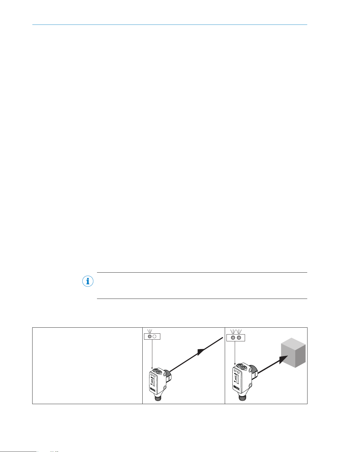
4 Operating and status indicators...................................................... 6
5 Mounting............................................................................................. 6
6 Electrical installation........................................................................ 7
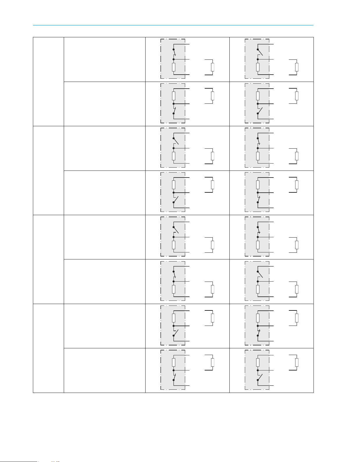
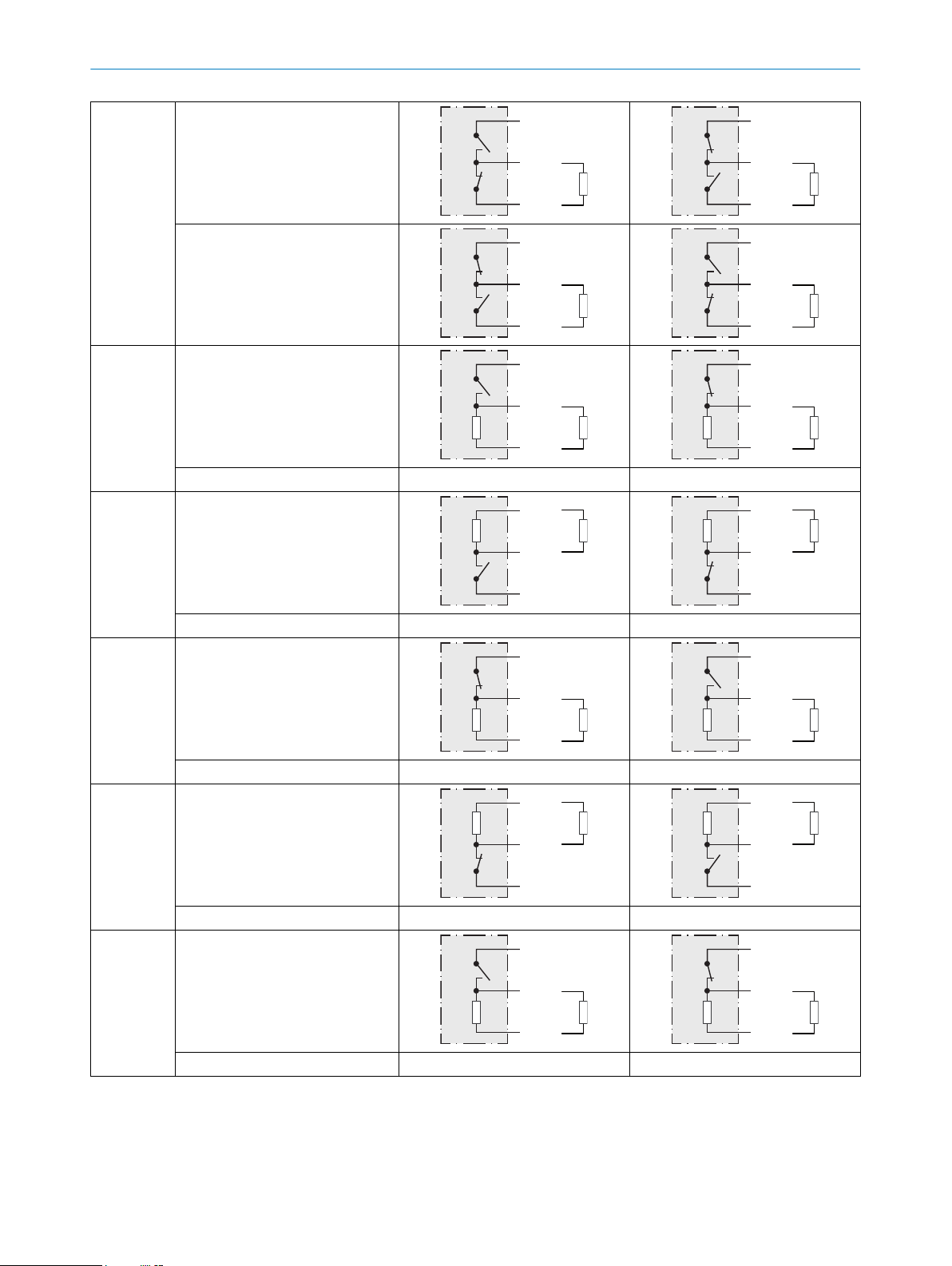
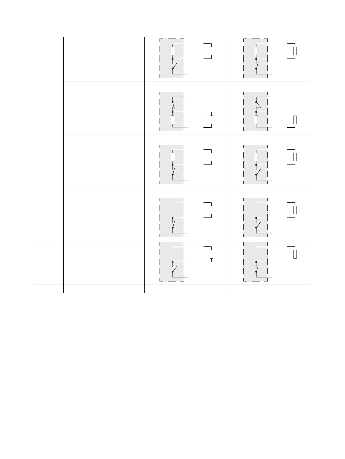
6.1 DC Output Operation................................................................................ 7
6.2 Connection Pinout.................................................................................... 11
6.3 Adjustments.............................................................................................. 12
7 Commissioning.................................................................................. 17
7.1 Alignment.................................................................................................. 17
7.2 Check the application conditions............................................................ 17
7.3 Setting....................................................................................................... 18
7.4 Additional functions.................................................................................. 20
8 Troubleshooting................................................................................. 20
9 Disassembly and disposal............................................................... 21
10 Maintenance...................................................................................... 21
11 Technical specifications................................................................... 22
11.1 Dimensional drawing................................................................................ 23
11.2 Process data structure............................................................................. 26
CONTENTS
48017850.1A15 / 2020-12-14 | SICK
Subject to change without notice

1 General safety notes
■Read the operating instructions before commissioning.
■
Connection, mounting, and configuration may only be performed by trained
specialists.
■
2006/42/EC
NO
SAFETY
Not a safety component in accordance with the EU Machinery Directive.
■
When commissioning, protect the device from moisture and contamination.
■These operating instructions contain information required during the life cycle of
the sensor.
HTB18L:
EN/IEC 60825-1:2014
IEC60825-1:2007
LASERCLASS 1
Laser
1
Maximum pulse power < 4,0 mW
Puls length: 4 µs
Wavelength: 650 - 670 nm
Complies with 21 CFR 1040.10
and 1040.11 except for deviations
pursuant to Laser Notice No. 50,
dated June 24, 2007
ATTENTION
WARNING: Interruption, manipulation or incorrect use can lead to hazardous exposure
due to laser radiation.
2 Notes on UL approval
All housing types are Type 1 enclosure.
3 Intended use
The HTB18L is an opto-electronic photoelectric background suppression proximity sen‐
sor (referred to as “sensor” in the following) for the optical, non-contact detection
of objects. If the product is used for any other purpose or modified in any way, any
warranty claim against SICK AG shall become void.
The sensor complies with the Radio Safety Requirements (EMC) for the industrial sector
(Radio Safety Class A). It may cause radio interference if used in a residential area.
GENERAL SAFETY NOTES 1
8017850.1A15 / 2020-12-14 | SICK
Subject to change without notice 5

4 Operating and status indicators
2
3
2 3
4
1
1Potentiometer adjustment (if
selected by model configuration) or
LED Indicators
2LED indicator green: supply voltage
active (with IO Link, flashes when IO
Link Communication is active)
3LED indicator yellow: status of
received light beam (with IO Link,
when teach mode is active)
4Signal strength light bar (if selected
by model configuration)
5 Mounting
Mount the sensor using a suitable mounting bracket (see the SICK range of acces‐
sories).
NOTE
Note the sensor's maximum permissible tightening torque of 0.56 Nm.
Note the preferred orientation of the sensor relative to the direction of object motion,
refer to figure 1.
Figure 1: Sensor orientation relative to object direction
4 OPERATING AND STATUS INDICATORS
68017850.1A15 / 2020-12-14 | SICK
Subject to change without notice

6 Electrical installation
Operation in standard I/O mode:
The sensors must be connected in a voltage-free state (UV = 0 V). The following informa‐
tion must be observed depending on the connection type:
– Plug connection: pin assignment
– Cable: wire color
Only apply voltage/switch on the voltage supply (UV > 0 V) once all electrical connec‐
tions have been established.
The green LED indicator on the top of the sensor lights up.
Operation in IO-Link mode: Connect the device to a suitable IO-Link master and inte‐
grate in the master or control via IODD/function block. The green LED indicator flashes
on the sensor. IODD and function block are available to download from www.sick.com
under the part number.
Explanation of connection terminology used in Tables 1-3:
BN = Brown
WH = White
BU = Blue
BK = Black
n. c. = no connection
Q1 = switching output 1 / IO Link Communication
Q2 = switching output 2
L+ = supply voltage (Uv)
L1 = AC supply voltage
M = common
N = AC common
Test = Test input
L.ON = light switching
D.ON = dark switching
NOTE
The sensor outputs may come equipped with an adjustable ON delay or OFF delay. This
is indicated by the model configuration (Hx18-xxxxx_).
6.1 DC Output Operation
Table 1: Output Operation
HTX18-_xxxxx
ELECTRICAL INSTALLATION 6
8017850.1A15 / 2020-12-14 | SICK
Subject to change without notice 7

-Axxxxx
Q1 = D.ON, PNP (≤ 100 mA)
+ (L+)
Q
‒ (M)
Load
+ (L+)
Q
‒ (M)
Load
Q2 = D.ON, NPN (≤ 100 mA)
+ (L+)
Q
‒ (M)
Load
+ (L+)
Q
‒ (M)
Load
-Bxxxxx
Q1 = L.ON, PNP (≤ 100 mA)
+ (L+)
Q
‒ (M)
Load
+ (L+)
Q
‒ (M)
Load
Q2 = L.ON, NPN (≤ 100 mA)
+ (L+)
Q
‒ (M)
Load
+ (L+)
Q
‒ (M)
Load
-Pxxxxx
Q1 = L.ON, PNP (≤ 100 mA)
+ (L+)
Q
‒ (M)
Load
+ (L+)
Q
‒ (M)
Load
Q2 = D.ON, PNP (≤ 100 mA)
+ (L+)
Q
‒ (M)
Load
+ (L+)
Q
‒ (M)
Load
-Nxxxxx
Q1 = L.ON, NPN (≤ 100 mA)
+ (L+)
Q
‒ (M)
Load
+ (L+)
Q
‒ (M)
Load
Q2 = D.ON, NPN (≤ 100 mA)
+ (L+)
Q
‒ (M)
Load
+ (L+)
Q
‒ (M)
Load
6 ELECTRICAL INSTALLATION
88017850.1A15 / 2020-12-14 | SICK
Subject to change without notice

-Fxxxxx1
Q1 = L.ON, PNP (≤ 100 mA)
+ (L+)
Q
‒ (M)
Load
+ (L+)
Q
‒ (M)
Load
Q2 = D.ON, PNP (≤ 100 mA)
+ (L+)
Q
‒ (M)
Load
+ (L+)
Q
‒ (M)
Load
-Vxxxxx Q1 = L.ON, PNP (≤ 100 mA)
+ (L+)
Q
‒ (M)
Load
+ (L+)
Q
‒ (M)
Load
Q2 = Health, PNP (≤ 100 mA) see table 2, page 11 see table 2, page 11
-Wxxxxx Q1 = L.ON, NPN (≤ 100 mA)
+ (L+)
Q
‒ (M)
Load
+ (L+)
Q
‒ (M)
Load
Q2 = Health, NPN (≤ 100 mA) see table 2, page 11 see table 2, page 11
-Xxxxxx Q1 = D.ON, PNP (≤ 100 mA)
+ (L+)
Q
‒ (M)
Load
+ (L+)
Q
‒ (M)
Load
Q2 = Health, PNP (≤ 100 mA) see table 2, page 11 see table 2, page 11
-Yxxxxx Q1 = D.ON, NPN (≤ 100 mA)
+ (L+)
Q
‒ (M)
Load
+ (L+)
Q
‒ (M)
Load
Q2 = Health, NPN (≤ 100 mA) see table 2, page 11 see table 2, page 11
-Gxxxxx Q1 = L.ON, PNP (≤ 100 mA)
+ (L+)
Q
‒ (M)
Load
+ (L+)
Q
‒ (M)
Load
Q2 = Alarm, PNP (≤ 100 mA) see table 2, page 11 see table 2, page 11
ELECTRICAL INSTALLATION 6
8017850.1A15 / 2020-12-14 | SICK
Subject to change without notice 9

-Hxxxxx Q1 = L.ON, NPN (≤ 100 mA)
+ (L+)
Q
‒ (M)
Load
+ (L+)
Q
‒ (M)
Load
Q2 = Alarm, NPN (≤ 100 mA) see table 2, page 11 see table 2, page 11
-Jxxxxx Q1 = D.ON, PNP (≤ 100 mA)
+ (L+)
Q
‒ (M)
Load
+ (L+)
Q
‒ (M)
Load
Q2 = Alarm, PNP (≤ 100 mA) see table 2, page 11 see table 2, page 11
-Kxxxxx Q1 = D.ON, NPN (≤ 100 mA)
+ (L+)
Q
‒ (M)
Load
+ (L+)
Q
‒ (M)
Load
Q2 = Alarm, NPN (≤ 100 mA) see table 2, page 11 see table 2, page 11
-Mxxxxx Q1 = D.ON, MOSFET (≤ 100 mA)
+ (L
Q
‒ (
+ (L1)
Q
‒ (N)
Load
+ (L1)
Q
‒ (N)
Load
-Lxxxxx Q1 = L.ON, MOSFET (≤ 100 mA)
+ (L1)
Q
‒ (N)
Load
+ (L
Q
‒ (
+ (L1)
Q
‒ (N)
Load
-Zxxxxx Special output operation Contact SICK Contact SICK
1PNP output diagram pictured; NPN also possible by connecting the Load to + (L+) and Q
6 ELECTRICAL INSTALLATION
10 8017850.1A15 / 2020-12-14 | SICK
Subject to change without notice

Table 2: Alarm/Health Operation
HTX18-_xxxxx
-Vxxxxx
-Xxxxxx Q2 = Health, PNP (≤ 100 mA)
+ (L+)
Q
‒ (M)
Load
+ (L+)
Q
‒ (M)
Load
-Wxxxxx
-Yxxxxx Q2 = Health, NPN (≤ 100 mA)
+ (L+)
Q
‒ (M)
Load
+ (L+)
Q
‒ (M)
Load
-Gxxxxx
-Jxxxxx Q2 = Alarm, PNP (≤ 100 mA)
+ (L+)
Q
‒ (M)
Load
+ (L+)
Q
‒ (M)
Load
-Hxxxxx
-Kxxxxx Q2 = Alarm, NPN (≤ 100 mA)
+ (L+)
Q
‒ (M)
Load
+ (L+)
Q
‒ (M)
Load
6.2 Connection Pinout
Table 3: Connection Pinout, DC, with or without IO Link
HT18 -x1xxxx -x2xxxx -x3xxxx -x4xxxx
1BN + (L+) + (L+) + (L+) + (L+)
2WH Q2 - Q2 2
3BU - (M) - (M) - (M) - (M)
4BK Q1 Q Q1 Q1
0.14 ... 1.5 mm2
12
3
IN = X A
2
1
4
3
IN = X A
12
4 3
IN = X A
ELECTRICAL INSTALLATION 6
8017850.1A15 / 2020-12-14 | SICK
Subject to change without notice 11

6.3 Adjustments
L/D Switching
The sensor may be specified with a Light Switching or Dark Switching
(L/D) selection potentiometer.
Light Switching is selected for the Q1 output by rotating the poten‐
tiometer counterclockwise to the stop position. The potentiometer tab
will point toward the “L” printed on the sensor housing.
Dark Switching is selected for the Q1 output by rotating the poten‐
tiometer clockwise to the stop position. The potentiometer tab will
point toward the “D” printed on the sensor housing.
CAUTION
Over rotation of the potentiometer past the stop positions will cause permanent dam‐
age to the sensor.
If complimentary outputs are specified (Hx18-Pxxxxx, Hx18-Nxxxxx, Hx18-Fxxxxx), the
Q2 output will always be opposite switching state of the Q1 output. Therefore, the Q2
output will be Dark Switching when the potentiometer is in the “L” position and Light
Switching in the potentiometer is in the “D” position. If bipolar outputs are specified
(Hx18-Axxxxx, Hx18-Bxxxxx), the Q2 output will always have the same switching state
as the Q1 output. The L/D selection potentiometer does not impact a Health or Alarm
output (if specified).
Table 4: Q1 output ACTIVE states with Light/Dark Switching selection potentiometer
HTX18-xxxx_
L/D Selection
Switch
-xxxxxE
-xxxxxH
-xxxxxI
-xxxxxK
-xxxxxP
Q1 = L.ON
Q1 = D.ON
Time delay
The sensor may be specified with an adjustable time delay. The delay
time is adjusted by rotating the 270° potentiometer.
Clockwise rotation in the direction of the “+” printed on the sensor will
increase the delay time (TDELAY). Maximum Delay time will occur at the
clockwise stop position.
Counter clockwise rotation in the direction of the “-“ printed on the
sensor will decrease the delay time. There will be no time delay at the
counter clockwise stop position.
CAUTION
Over rotation of the potentiometer past the stop positions will cause permanent dam‐
age to the sensor.
A L/D selection switch may be specified with an adjustable time delay. Adjustable time
delay does not impact a Health or Alarm output (if specified).
6 ELECTRICAL INSTALLATION
12 8017850.1A15 / 2020-12-14 | SICK
Subject to change without notice

Table 5: Output ACTIVE states for complimentary output variants with adjustable time delay
HTX18-Pxxxx_
HTX18-Nxxxx_
HTX18-Fxxxx_
No Time Delay
Q1 = L.ON
Q2 = D.ON
Adjustabl
e ON
Delay1
-xxxxxC
-xxxxxF
-xxxxxI2
-xxxxxM
Q1 = L.ON
Q2 = D.ON
-xxxxxI3
Q1 = D.ON
Q2 = L.ON
Adjustabl
e OFF
Delay1
-xxxxxD
-xxxxxG
-xxxxxK2
-xxxxxN
Q1 = L.ON
Q2 = D.ON
-xxxxxK3
Q1 = D.ON
Q2 = L.ON
1ON or OFF Delay naming applies to the Q1 output
2L/D Selection Switch in in the “L” Light Switching position
3L/D Selection Switch in in the “D” Dark Switching position
ELECTRICAL INSTALLATION 6
8017850.1A15 / 2020-12-14 | SICK
Subject to change without notice 13

Table 6: Output ACTIVE states for HTX18-Bxxxx_ variants with adjustable time delay
HTX18-Bxxxx_
No Time Delay
Q1 = L.ON
Q2 = L.ON
Adjustabl
e ON
Delay
-xxxxxC
-xxxxxF
-xxxxxI1
-xxxxxM
Q1 = L.ON
Q2 = L.ON
-xxxxxI2
Q1 = D.ON
Q2 = D.ON
Adjustabl
e OFF
Delay
-xxxxxD
-xxxxxG
-xxxxxK1
-xxxxxN
Q1 = L.ON
Q2 = L.ON
-xxxxxK2
Q1 = D.ON
Q2 = D.ON
1L/D Selection Switch in in the “L” Light Switching position
2L/D Selection Switch in in the “D” Dark Switching position
6 ELECTRICAL INSTALLATION
14 8017850.1A15 / 2020-12-14 | SICK
Subject to change without notice

Table 7: Output ACTIVE states for HTX18-Axxxx_ variants with adjustable time delay
HTX18-Axxxx_
No Time Delay
Q1 = D.ON
Q2 = D.ON
Adjustabl
e ON
Delay
-xxxxxC
-xxxxxF
-xxxxxI1
-xxxxxM
Q1 = D.ON
Q2 = D.ON
-xxxxxI2
Q1 = L.ON
Q2 = L.ON
Adjustabl
e OFF
Delay
-xxxxxD
-xxxxxG
-xxxxxK1
-xxxxxN
Q1 = D.ON
Q2 = D.ON
-xxxxxK2
Q1 = L.ON
Q2 = L.ON
1L/D Selection Switch in in the “D” Dark Switching position
2L/D Selection Switch in in the “L” Light Switching position
ELECTRICAL INSTALLATION 6
8017850.1A15 / 2020-12-14 | SICK
Subject to change without notice 15

Table 8: Q1 output ACTIVE states for Dark Switching variants with Alarm/Health and adjustable
time delay
HTX18-Vxxxx_
HTX18-Wxxxx_
HTX18-Gxxxx_
HTX18-Hxxxx_
No Time Delay Q1 = L.ON
Adjustabl
e ON
Delay
-xxxxxC
-xxxxxF
-xxxxxI1
-xxxxxM
Q1 = L.ON
-xxxxxI2Q1 = D.ON
Adjustabl
e OFF
Delay
-xxxxxD
-xxxxxG
-xxxxxK1
-xxxxxN
Q1 = L.ON
-xxxxxK2Q1 = D.ON
1L/D Selection Switch in in the “L” Light Switching position
2L/D Selection Switch in in the “D” Dark Switching position
Table 9: Q1 output ACTIVE states for Dark Switching variants with Alarm/Health and adjustable
time delay
HTX18-Xxxxx_
HTX18-Yxxxx_
HTX18-Jxxxx_
HTX18-Kxxxx_
No Time Delay Q1 = D.ON
Adjustabl
e ON
Delay
-xxxxxC
-xxxxxF
-xxxxxI1
-xxxxxM
Q1 = D.ON
-xxxxxI2Q1 = L.ON
Adjustabl
e OFF
Delay
-xxxxxD
-xxxxxG
-xxxxxK1
-xxxxxN
Q1 = D.ON
6 ELECTRICAL INSTALLATION
16 8017850.1A15 / 2020-12-14 | SICK
Subject to change without notice

-xxxxxK2Q1 = L.ON
1L/D Selection Switch in in the “D” Dark Switching position
2L/D Selection Switch in in the “L” Light Switching position
7 Commissioning
7.1 Alignment
Sensor with red light:
Align sensor on object. Select the position so that the red emitted light beam hits the
center of the object. You must ensure that the optical opening (front screen) of the
sensor is completely clear [see figure 2].
Figure 2: Alignment
7.2 Check the application conditions
Sensing range
Check the application conditions: Adjust the sensing range and distance to the object
or background and the remission capability of the object according to the correspond‐
ing diagram [see figure 3] (x = sensing range, y = transition range between the set
sensing range and suppression of the background as a % of the sensing range (object
remission/background remission)). Remission: 6% = black 1, 18% = gray 2, 90% =
white 3 (referring to standard white as per DIN 5033). We recommend making the
adjustments using an object with a low remission.
The minimum distance (= y) for background suppression can be determined from
diagram [ figure 3 1] as follows:
Example: x = 100 mm, y = 10 => 10% of 100 mm = 10 mm. That is, the background is
suppressed at a distance of > mm from the sensor.
HTB18:
yx
white back-
ground (90%)
x = 100 mm, y = 10 mm
(= 10% of 100 mm)
COMMISSIONING 7
8017850.1A15 / 2020-12-14 | SICK
Subject to change without notice 17

0
5
10
15
20
25
50
(1.97)
100
(3.94)
200
(7.87)
250
(9.84)
300
(11.81)
0
% of sensing range
3
2
1
150
(5.91)
Distance in mm (inch)
6%/90% 18%/90%
90%/90%
Figure 3: HTB18, % of sensing range
1
2
3
150 200
3 20
5 20 150
150 300
3 20
A B
A = detection distance (depending on
object remission)
B = adjustment range
HTB18L:
20
15
10
5
0
% of sensing range
050
(1.97)
100
(3.94)
150
(5.91)
200
(7.87)
250
(9.84)
300
(11.81)
Distance in mm (inch)
3
2
1
90%/90%
20%/90%
6%/90%
Figure 4: HTB18L, % of sensing range
yx
white back-
ground (90%)
x = 250 mm, y = 15 mm
(= 15% of 250 mm)
1
2
3
25030
30 250
25030
300
300
A B
A = detection distance (depending on
object remission)
B = adjustment range
y
x
Figure 5: Description of the sensing range areas
7.3 Setting
Sensing range setting
7 COMMISSIONING
18 8017850.1A15 / 2020-12-14 | SICK
Subject to change without notice

Sensor which it is not possible to set: The sensor is adjusted and ready for operation.
Refer to graphic to check the function. If the switching output fails to behave in accor‐
dance with graphic, check application conditions. See section Fault diagnosis.
Sensor with potentiometer (without IO Link):
The sensing range is adjusted relative to the background with the potentiometer (type:
270°).
Clockwise rotation: sensing range increased; counterclockwise rotation: sensing range
reduced.
Turn the potentiometer clockwise until the yellow LED indicator lights up. When an
object is moved into the path of the beam, the yellow LED indicator must go out. If the
yellow LED indicator remains lit when an object is moved into the path of the beam,
repeat the adjustment.
Sensor with potentiometer (with IO Link):
The sensing range is adjusted relative to the background with the potentiometer (type:
270°).
Clockwise rotation: to teach mode; counterclockwise rotation: to run mode. Turn the
potentiometer clockwise to teach mode until yellow LED begins blinking. Set object
at desired sensing range. Turn the potentiometer counterclockwise to run mode until
yellow LED stops blinking. The yellow LED should remain lit. Remove the object from
light beam, LED will turn off.
We recommend placing the switching state in the object, e.g., see figure 6. Once the
sensing range has been adjusted, the object is removed from the path of the beam,
which causes the background to be suppressed and the switching output to change
(see graphic C).
0 %
100 %
0 %
100 %
0 %
100 %
0 %
100 %
0 %
100 %
0 %
100 %
0 %
100 %
0 %
100 %
Sensing range min. Sensing range max.
Set switching point
Figure 6: Signal strength light bar during adjustment
The optimum setting can be achieved and checked using the signal strength light bar
on the back of the sensor. The LEDs on the signal strength light bar light up in relation
to the object position and the set switching point. If no LEDs or only the red LEDs light
up, the object is positioned behind the set switching point and cannot be detected. The
first yellow LED lights up when the object is in the set switching point. The green LEDs
light up when the object is between the sensor and the set switching point. The closer
the object is to the switching point, the more green LEDs will light up (see figure 6).
The sensor is adjusted and ready for operation. Refer to graphics see table 1, page 7
to check the function. If the switching output fails to behave in accordance the graphic,
check application conditions. See section Fault diagnosis.
Please refer to the enclosed operating instructions for the IO-Link photoelectric sensor
for information about adjusting the IO-Link sensing range.
The sensor is adjusted and ready for operation.
COMMISSIONING 7
8017850.1A15 / 2020-12-14 | SICK
Subject to change without notice 19

7.4 Additional functions
Alarm / Health output
The sensor (HTB18(L)) features a pre-failure notification output (“Q2” in connection
diagram [B], if the alarm option is selected), which issues a notification if the signal
strength of the light being received is not sufficient. Possible causes: Sensor is conta‐
minated, sensor is out of alignment. In the good state: LOW (UV < V); if excessively
contaminated: HIGH (>+UV- V). The LED indicator flashes in this case.
Health output: The sensor (HTB18(L)) features a health status notification output (“Q2”
in connection diagram [B], if the health option is selected), which issues a notification if
the signal strength of the light being received is sufficient. Possible causes, if the signal
strength is not sufficient: Sensors are contaminated, sensors are out of alignment, or
cable is damaged. In the good state: HIGH (>+UV- V); if excessively contaminated or in
the event of cable interruption: LOW (UV < V). The LED indicator flashes in this case.
Time types
Time types: HTB18(L) with optional On-delay or Off-Delay adjustment: t0 = no time
delay, t1 = time delay when object is detected, t2 = time delay when no object is
detected. The time setting can be selected using the potentiometer according to A.
Timer stages can be set from 0 to 2 seconds.
8 Troubleshooting
The Troubleshooting table indicates measures to be taken if the sensor stops working.
Table 10: Troubleshooting
LED indicator/fault pattern Cause Measures
Yellow LED does not light up
even though the light beam is
aligned to the object and the
object is within the set sensing
range
No voltage or voltage below
the limit values
Check the power supply,
check all electrical connec‐
tions (cables and plug connec‐
tions)
Voltage interruptions Ensure there is a stable power
supply without interruptions
Sensor is faulty If the power supply is OK,
replace the sensor
Green LED flashes IO-Link communication -
Switching outputs not accord‐
ing to graphic C
IO-Link communication -
Switching outputs not accord‐
ing to graphic C
Parameter settings made
manually, which deviate from
the standard
Initiate a factory reset. The
switching outputs are reset to
factory settings.
Yellow LED flashes; if Health is
present then take note of the
corresponding output signal; if
Alarm is present then take note
of the corresponding output
signal
Sensor is still ready for oper‐
ation, but the operating con‐
ditions are not ideal/addition‐
ally with health output: power
supply interrupted
Check the operating condi‐
tions: Fully align the beam
of light (light spot) with the
object / Clean the optical sur‐
faces / Check sensing range
and adjust if necessary, see
figures in chapter 7.2 / With
health output: Check the volt‐
age supply, check all electrical
connections (cables and plug
connections).
7 COMMISSIONING
20 8017850.1A15 / 2020-12-14 | SICK
Subject to change without notice
Other manuals for SureSense HTB18L Series
1
This manual suits for next models
1
Table of contents
Other SICK Accessories manuals