5 Fault diagnosis
Table Fault diagnosis indicates which measures are to be taken if the sensor stops working.
6 Table Fault diagnosis
LED indicator/fault pattern /
LED indicator/fault pattern
Cause /
Cause
Measures /
Measures
Green LED does not light up /
Green LED does not light up
No voltage or voltage below
the limit values /
No voltage or voltage below
the limit values
Check the power supply,
check all electrical connecti‐
ons (cables and plug connecti‐
ons) /
Check the power supply,
check all electrical connecti‐
ons (cables and plug connecti‐
ons)
Green LED does not light up /
Green LED does not light up
Voltage interruptions /
Voltage interruptions
Ensure there is a stable power
supply without interruptions /
Ensure there is a stable power
supply without interruptions
Green LED does not light up /
Green LED does not light up
Sensor is faulty /
Sensor is faulty
If the power supply is OK,
replace the sensor /
If the power supply is OK,
replace the sensor
Yellow LED flashes /
Yellow LED flashes
Sensor is still ready for opera‐
tion, but the operating conditi‐
ons are not ideal /
Sensor is still ready for opera‐
tion, but the operating conditi‐
ons are not ideal
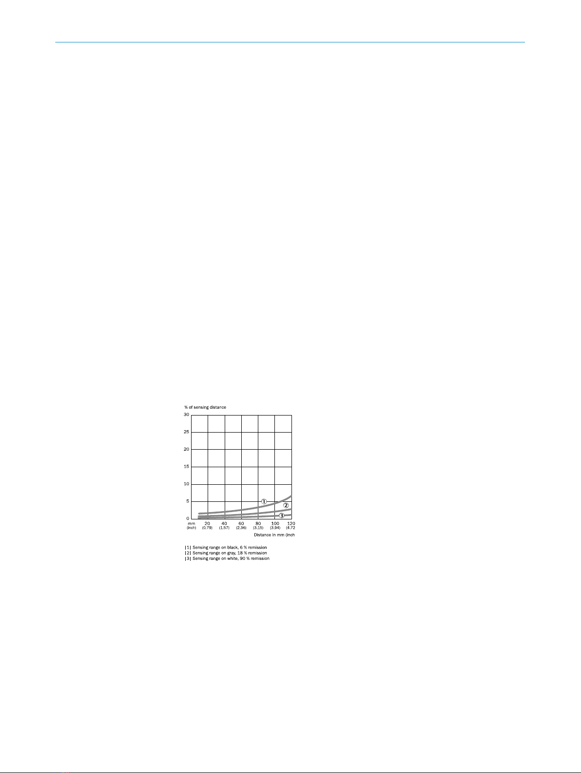
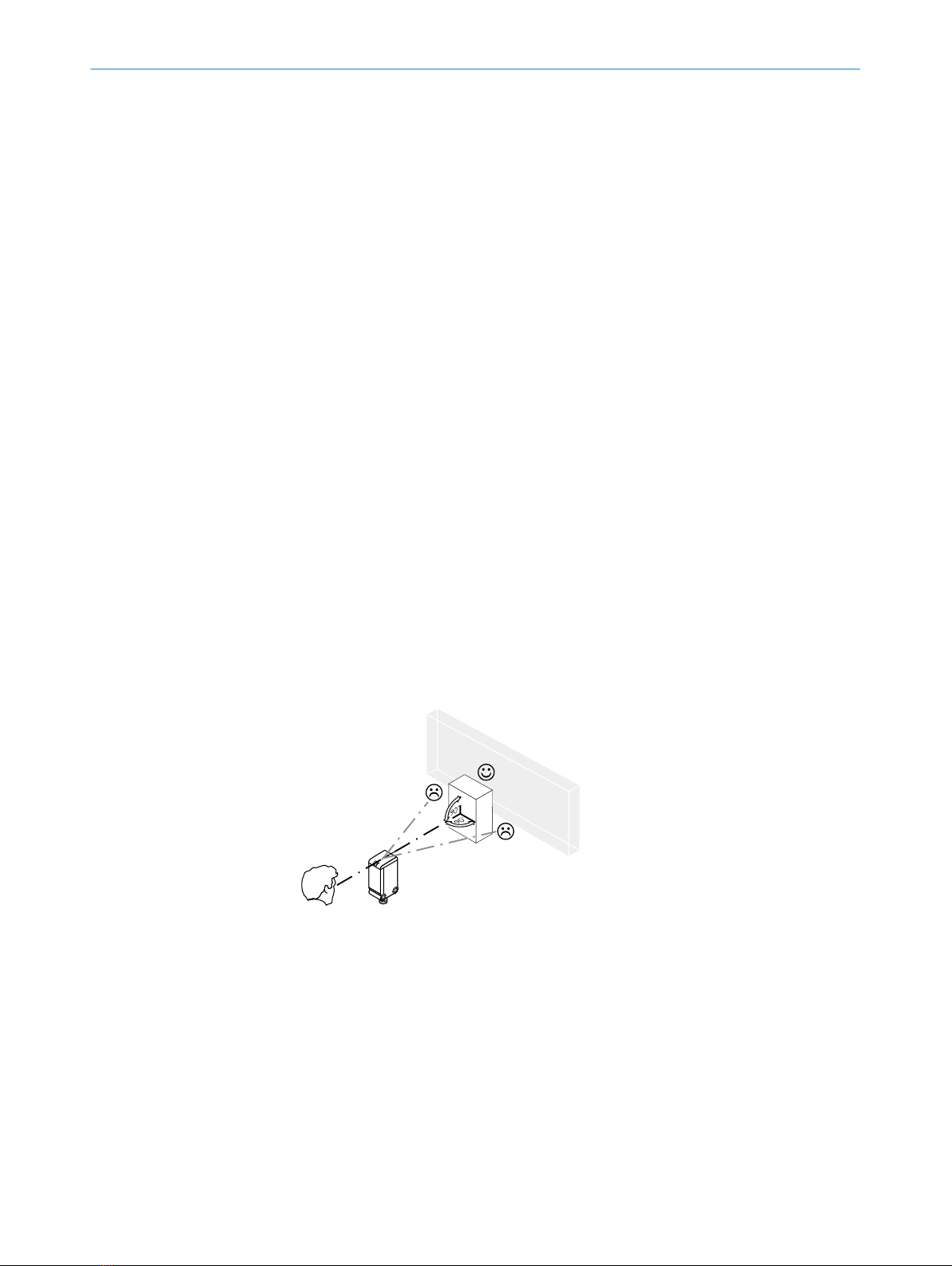
Check the operating conditi‐
ons: Fully align the beam of
light (light spot) with the
object. / Clean the optical sur‐
faces . / Readjust the sensiti‐
vity / Check sensing range
and adjust if necessary; see
graphic F. /
Check the operating conditi‐
ons: Fully align the beam of
light (light spot) with the
object. / Clean the optical sur‐
faces . / Readjust the sensiti‐
vity / Check sensing range
and adjust if necessary; see
graphic F.
Yellow LED lights up, no object
in the path of the beam /
Yellow LED lights up, no object
in the path of the beam
/ Distance between the sen‐
sor and the background is too
short /
/ Distance between the sen‐
sor and the background is too
short
Reduce the sensing range,
see graphic F /
Reduce the sensing range,
see graphic F
Object is in the path of the
beam, yellow LED does not
light up /
Object is in the path of the
beam, yellow LED does not
light up
Distance between the sensor
and the object is too long or
sensing range is set too
short /
Distance between the sensor
and the object is too long or
sensing range is set too short
Increase the sensing range,
see graphic F /
Increase the sensing range,
see graphic F
FAULT DIAGNOSIS 5
8012136.YM43 | SICK
Subject to change without notice 5