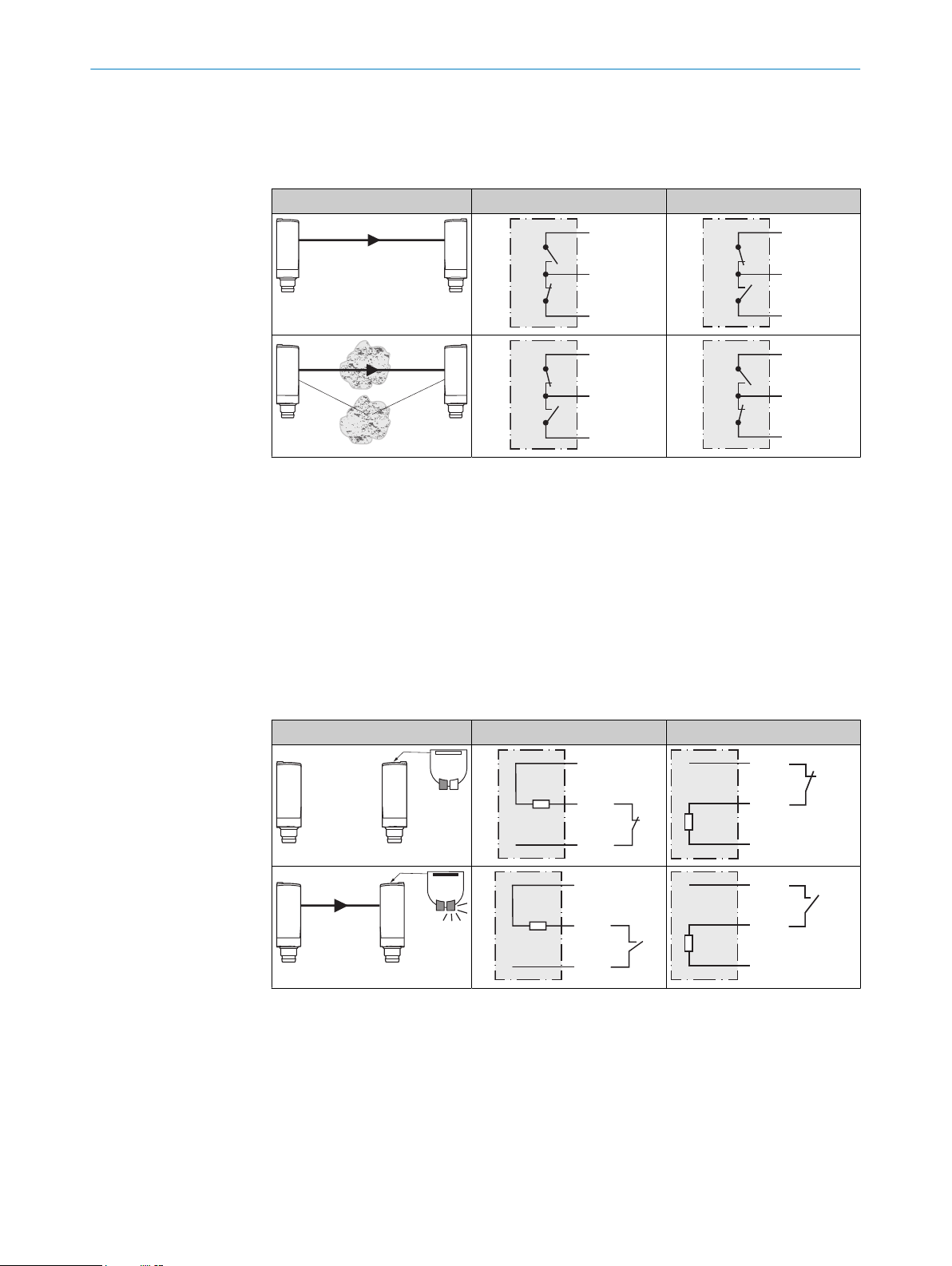
is contaminated, sensor is out of alignment, cable is damaged. In the good state: HIGH
(1), if excessively contaminated or in the event of cable interruption LOW (0). The yellow
LED indicator flashes in this case.
Table 7: Alarm / Health
Alarm (≤ 100 mA) Health (≤100 mA)
Test input
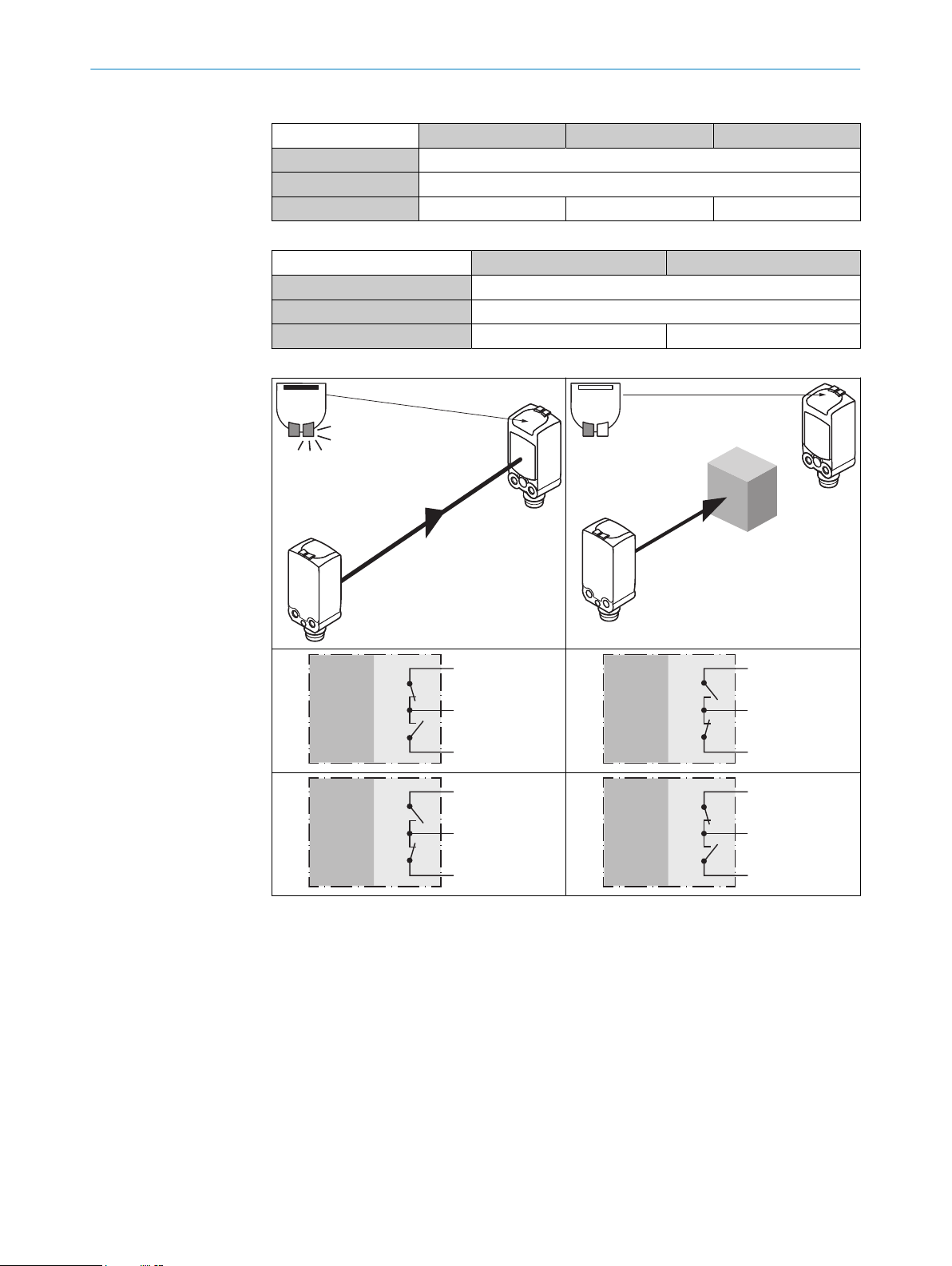
Test input: The WSE4F sensors feature a test input (“Test” on the connection diagram
[see table 2, page 7]), which can be used to switch the sender off and, therefore, check
that the sensor is functioning correctly: If female cable connectors with LED indicators
are used, you must ensure that the TI is assigned accordingly.
It is important that there is no object between the sender and receiver, activate the test
input (see the connection diagram [see table 2, page 7]).
The send LED is shut down or the detection of an object is simulated. Refer to table 8
to check the function. If the switching output fails to behave in accordance with the
following table, check the application conditions, see "Troubleshooting", page 12.
Table 8: Test
Test → M Test → L+
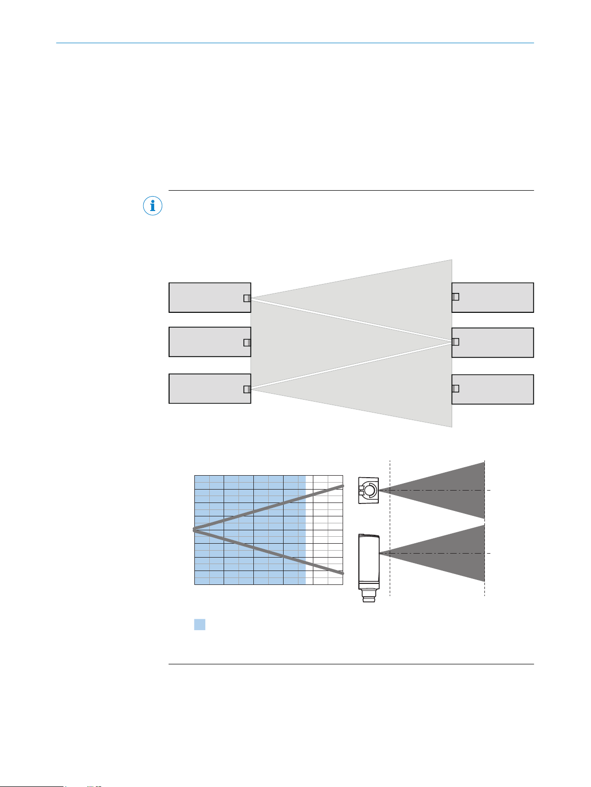
7 Commissioning
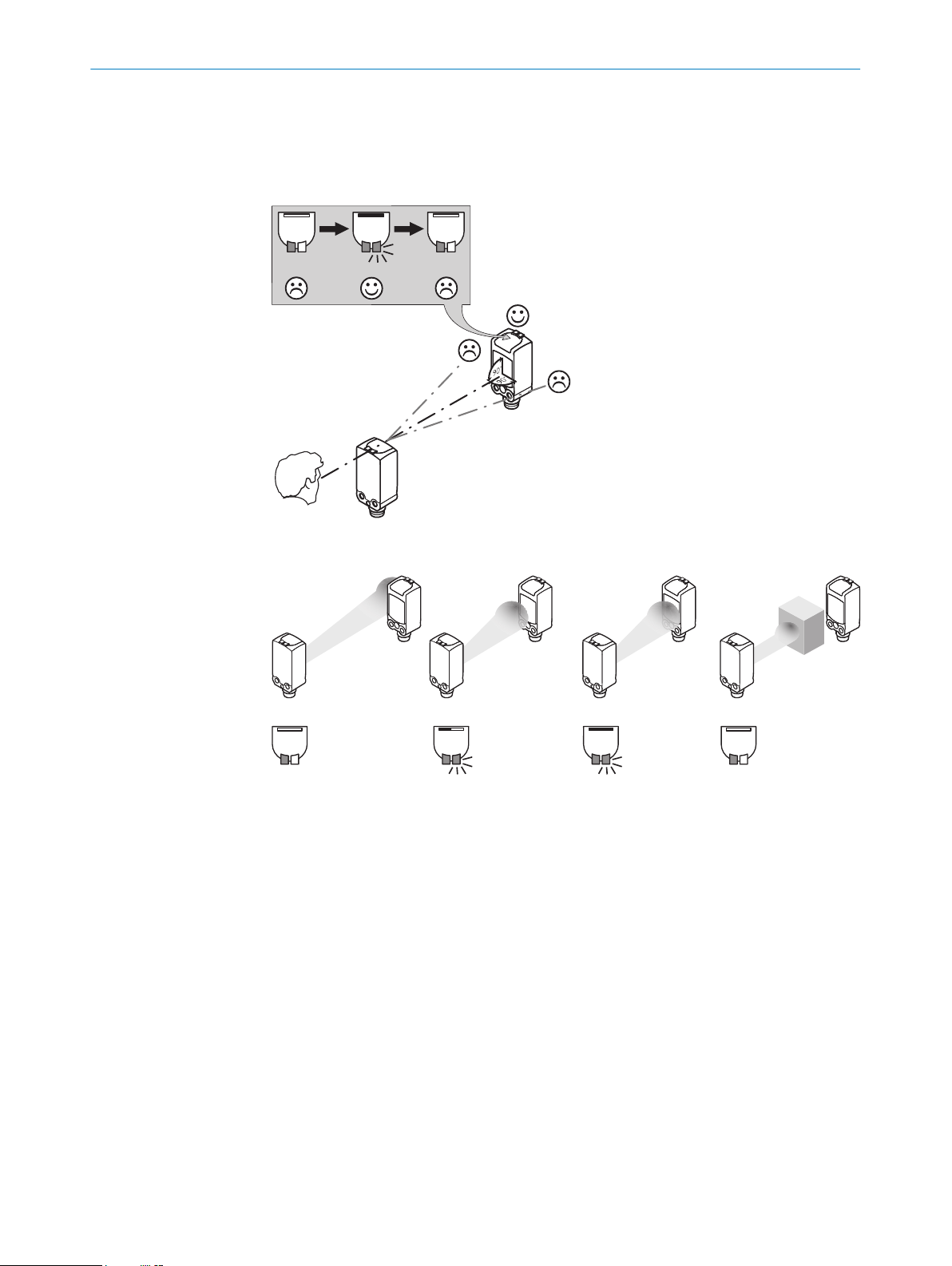
7.1 Alignment
WSO4FP: Align the sender (WSO4F) with the receiver (WEO4F). Select the position so
that the red emitted light beam hits the receiver. Tip: Use white paper or a reflector as
an alignment aid. The sender must have a clear view of the receiver, with no object in
the path of the beam [see figure 3]. You must ensure that the optical openings (front
screen) of the sensors are completely clear.
ADDITIONAL FUNCTIONS 6
8025304 / 2021-05-12 | SICK
Subject to change without notice 9