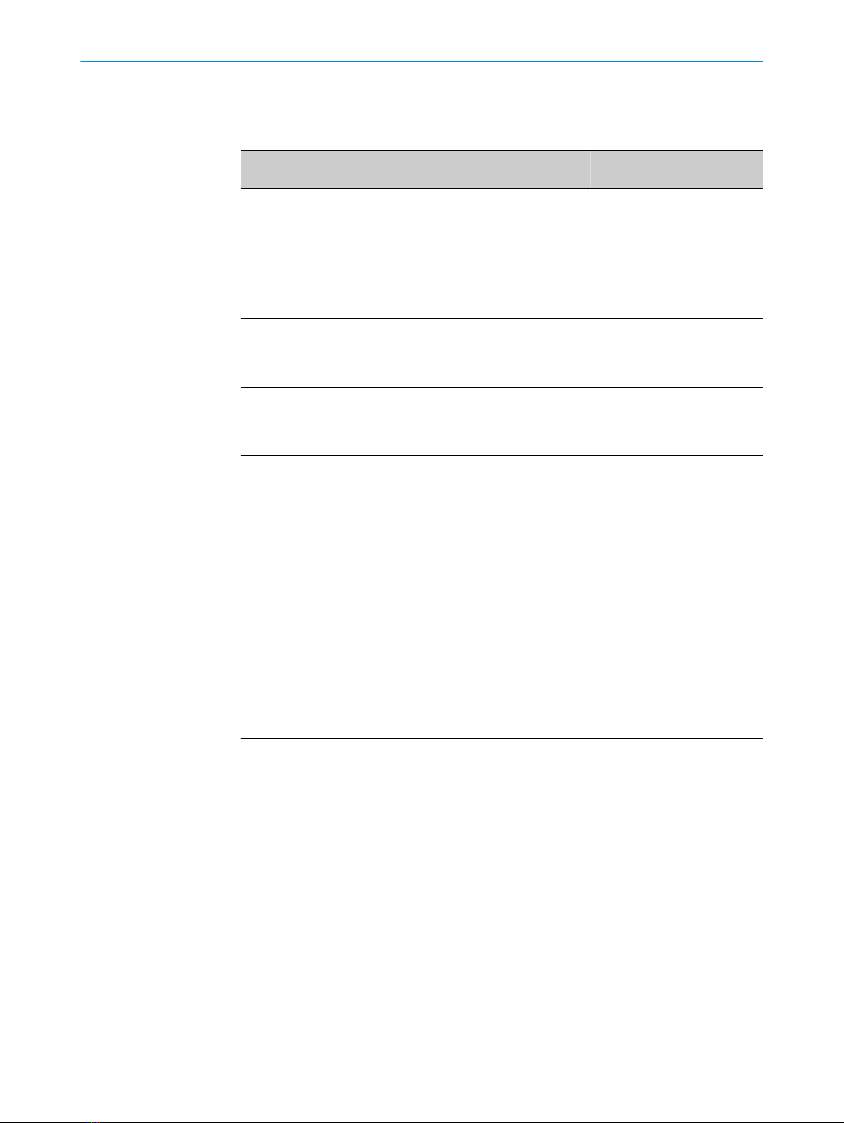
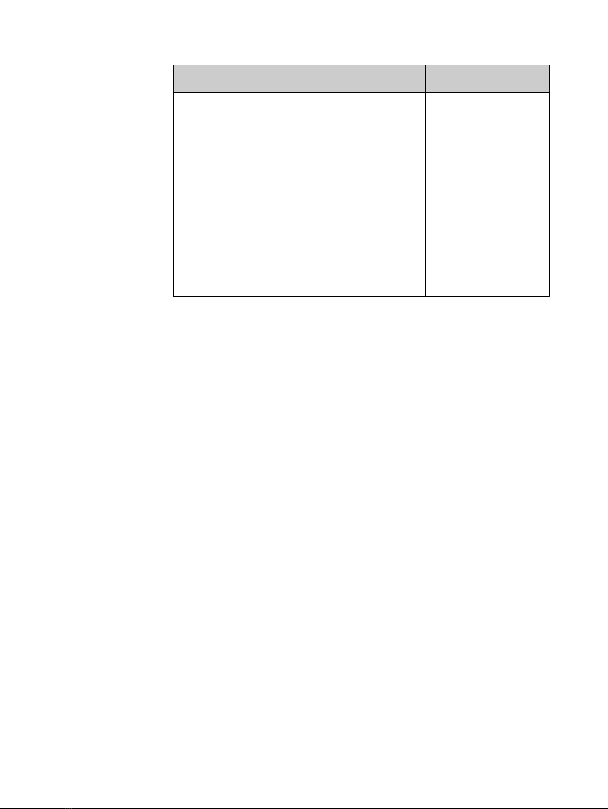
6 Table Fault diagnosis
LED indicator/fault pattern /
LED indicator/fault pattern
Cause /
Cause
Measures /
Measures
Green LED does not light up /
Green LED does not light up
No voltage or voltage below
the limit values /
No voltage or voltage below
the limit values
Check the power supply,
check all electrical connecti‐
ons (cables and plug connecti‐
ons) /
Check the power supply,
check all electrical connecti‐
ons (cables and plug connecti‐
ons)
Green LED does not light up /
Green LED does not light up
Voltage interruptions /
Voltage interruptions
Ensure there is a stable power
supply without interruptions /
Ensure there is a stable power
supply without interruptions
Green LED does not light up /
Green LED does not light up
Sensor is faulty /
Sensor is faulty
If the power supply is OK, re‐
place the sensor /
If the power supply is OK, re‐
place the sensor
Yellow LED flashes /
Yellow LED flashes
Sensor is still ready for opera‐
tion, but the operating conditi‐
ons are not ideal /
Sensor is still ready for opera‐
tion, but the operating conditi‐
ons are not ideal
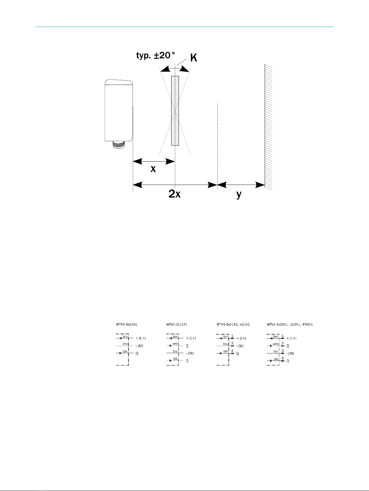
Check the operating conditi‐
ons: Fully align the beam of
light (light spot) with the back‐
ground. / Clean the optical
surfaces . / Readjust the sen‐
sitivity (potentiometer) /
Check sensing range and ad‐
just if necessary; see graphic
F. /
Check the operating conditi‐
ons: Fully align the beam of
light (light spot) with the back‐
ground. / Clean the optical
surfaces . / Readjust the sen‐
sitivity (potentiometer) /
Check sensing range and ad‐
just if necessary; see graphic
F.
7 Disassembly and disposal
The sensor must be disposed of according to the applicable country-specific regulati‐
ons. Efforts should be made during the disposal process to recycle the constituent ma‐
terials (particularly precious metals).
8 Maintenance
SICK sensors are maintenance-free.
We recommend doing the following regularly:
•Clean the external lens surfaces
•Check the screw connections and plug-in connections
No modifications may be made to devices.
Subject to change without notice. Specified product properties and technical data are
not written guarantees.
6 TABLE FAULT DIAGNOSIS
48011167.126R | SICK
Subject to change without notice