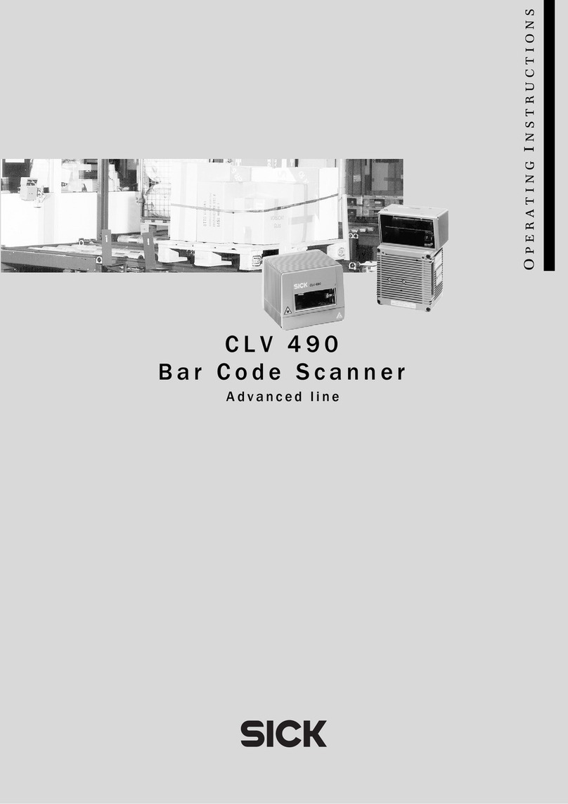
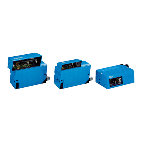
SICK CLV62 Series Manual

TECHNICAL INFORMATION
CLV62x, CLV63x and CLV64x with IP69K Protec‐
tive Housing
Stationary Bar Code Scanners

Described product
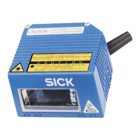
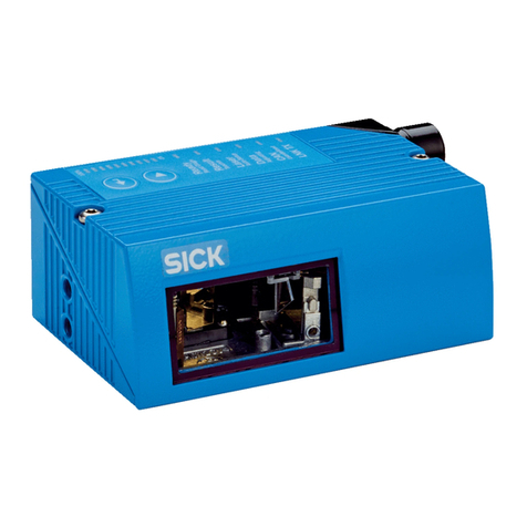
CLV62x, CLV63x and CLV64x fixed mount bar code scanner in IP69K protective housing
Manufacturer
SICK AG
Erwin-Sick-Str. 1
79183 Waldkirch
Germany
Legal information
This work is protected by copyright. Any rights derived from the copyright shall be
reserved for SICK AG. Reproduction of this document or parts of this document is
only permissible within the limits of the legal determination of Copyright Law. Any modi‐
fication, abridgment or translation of this document is prohibited without the express
written permission of SICK AG.
The trademarks stated in this document are the property of their respective owner.
© SICK AG. All rights reserved.
Original document
This document is an original document of SICK AG.
25
2T E C H N I C A L I N F O R M A T I O N | CLV62x, CLV63x and CLV64x with IP69K Protective Housing 8021479/19ZB/2021-10-29 | SICK
Subject to change without notice

Contents
1 About this document........................................................................ 5
1.1 Information on the Technical Information............................................... 5
1.2 Explanation of symbols............................................................................ 5
2 Safety information............................................................................ 7
2.1 Intended use............................................................................................. 7
2.2 Improper use............................................................................................. 7
2.3 Cybersecurity............................................................................................ 7
2.3.1 Configuration with profile programming................................. 8
2.4 Hazard warnings and operational safety................................................. 8
2.4.1 Laser radiation......................................................................... 8
3 Product description........................................................................... 12
3.1 Product ID.................................................................................................. 12
3.1.1 Type label................................................................................. 12
3.2 Design........................................................................................................ 13
3.3 Scope of delivery....................................................................................... 15
3.4 Differences: Devices in IP65 standard housing and devices in IP69K
protective housing.................................................................................... 17
3.5 Reading fields........................................................................................... 18
4 Transport and storage....................................................................... 21
4.1 Bar code scanners CLV62x, CLV63x and CLV64x with IP69K protec‐
tive housing............................................................................................... 21
5 Mounting............................................................................................. 22
5.1 Overview of mounting procedure............................................................. 22
5.2 Mounting requirements............................................................................ 22
5.3 Mounting options...................................................................................... 22
5.4 Mounting the protective double bushing on the protective housing..... 23
5.4.1 Assembly with use of the Ethernet connection..................... 23
5.4.2 Assembly without use of the Ethernet connection................ 25
6 Electrical installation........................................................................ 28
6.1 Safety......................................................................................................... 28
6.1.1 Notes on electrical installation............................................... 28
6.2 Prerequisites for safe operation of the device in a system.................... 29
6.3 Pin assignment of the connections......................................................... 29
7 Technical data.................................................................................... 31
7.1 CLV62x bar code scanner in the IP69K protective housing.................. 31
7.2 CLV63x bar code scanner in the IP69K protective housing.................. 33
7.3 CLV64x bar code scanner in the IP69K protective housing.................. 36
8 Accessories........................................................................................ 40
CONTENTS
8021479/19ZB/2021-10-29 | SICK T E C H N I C A L I N F O R M A T I O N | CLV62x, CLV63x and CLV64x with IP69K Protective Housing 3
Subject to change without notice
8.1 Brackets.................................................................................................... 40
8.2 Cables........................................................................................................ 40
CONTENTS
4T E C H N I C A L I N F O R M A T I O N | CLV62x, CLV63x and CLV64x with IP69K Protective Housing 8021479/19ZB/2021-10-29 | SICK
Subject to change without notice

1 About this document
1.1 Information on the Technical Information
This Technical Information is a supplement to the operating instructions for the follow‐
ing fixed mount bar code scanners:
•CLV62x operating instructions
•CLV63x, CLV64x, CLV65x operating instructions (combined operating instructions)
The information herein supplements the mounting and electrical installation informa‐
tion for devices equipped with an IP69K protective housing. This includes the CLV62x,
CLV63x and CLV64x. The CLV65x does not offer a variant with an IP69K protective
housing.
The operating instructions for the individual product families can be downloaded online
from the respective product page on the Internet.
Table 1: Operating instructions for the CLV62x, CLV63x and CLV64x fixed mount bar code
scanners
Device Part number of
operating instruc‐
tions
German
Part number of
operating instruc‐
tions
English
Part number of
operating instruc‐
tions
French
Product page on the
Internet
CLV62x 8011964 8011965 8019585 www.sick.com/CLV62x
CLV63x 8019587 8019588 8019589 www.sick.com/CLV63x
CLV64x 8019587 8019588 8019589 www.sick.com/CLV64x
The operating instructions may be available in other language versions.
This Technical Information contains the device-specific information on the device,
mounting and electrical connection. For more information, see the operating instruc‐
tions of the respective product family.
Adherence to all the specified safety notes, warnings and guidelines in this Technical
Information and in the corresponding operating instructions of the device used is a
prerequisite for working safely.
This Technical Information is intended to be used by qualified personnel and electrical
specialists.
NOTE
Carefully read this Technical Information and the operating instructions of the fixed
mount bar code scanner before carrying out any work with the device.
1.2 Explanation of symbols
Warnings and important information in this document are labeled with symbols. Sig‐
nal words introduce the instructions and indicate the extent of the hazard. To avoid
accidents, damage, and personal injury, always comply with the instructions and act
carefully.
DANGER
… indicates a situation of imminent danger, which will lead to a fatality or serious
injuries if not prevented.
ABOUT THIS DOCUMENT 1
8021479/19ZB/2021-10-29 | SICK T E C H N I C A L I N F O R M A T I O N | CLV62x, CLV63x and CLV64x with IP69K Protective Housing 5
Subject to change without notice

WARNING
… indicates a potentially dangerous situation, which may lead to a fatality or serious
injuries if not prevented.
CAUTION
… indicates a potentially dangerous situation, which may lead to minor/slight injuries if
not prevented.
NOTICE
… indicates a potentially harmful situation, which may lead to material damage if not
prevented.
NOTE
… highlights useful tips and recommendations as well as information for efficient and
trouble-free operation.
1 ABOUT THIS DOCUMENT
6T E C H N I C A L I N F O R M A T I O N | CLV62x, CLV63x and CLV64x with IP69K Protective Housing 8021479/19ZB/2021-10-29 | SICK
Subject to change without notice

2 Safety information
2.1 Intended use
The device consists of a fixed mount bar code scanner of the product family CLV62x,
CLV63x or CLV64x in the Ethernet variant with a protective housing with enclosure
rating IP69K.
The protective housing comprises two parts:
•Protective housing with a fixed mount bar code scanner permanently installed at
the factory
•Accompanying protective double bushing including sealing material for the two
electrical connections
When using suitable cables and correctly mounting the protective double bushing, the
device is protected against water from high-pressure or steam cleaners and as well as
against dust. For the specification, see "Technical data", page 31.
Conditions for specified enclosure rating
NOTICE
The following requirements must be met in order to achieve the IP69K enclosure rating:
•Use only the connection cables specified by SICK.
•Seal the two cable outlets at the protective double bushing with the corresponding
O-rings.
•The recessed flat seal on the side facing the protective housing is undamaged.
The O-rings are included in the device scope of delivery and are matched to the outer
diameters of the plug connectors.
The device is an intelligent, opto-electronic SICK ID sensor and is used for automated,
fixed identification and decoding of bar codes on moving or stationary objects. The
device transmits the data content of the decoded bar codes to a higher-level control
(PLC) for coordinating further processing.
SICK AG assumes no liability for losses or damage arising from the use of the product,
either directly or indirectly. This applies in particular to use of the product that does not
conform to its intended purpose and is not described in this documentation.
2.2 Improper use
■The device must not be used in explosion-hazardous areas.
■The protective housing of the factory-installed fixed mount bar code scanner must
not be opened.
■The device does not constitute a safety-relevant device according to the EC Machi‐
nery Directive (2006/42 / EC).
■Any other use that is not described as intended use is prohibited.
■The use of mounting accessories not approved by SICK AG is at your own risk.
2.3 Cybersecurity
To protect against cybersecurity threats, it is necessary to continuously monitor and
maintain a comprehensive and holistic cybersecurity concept. A suitable concept com‐
prises organizational, technical, procedural, electronic, and physical levels of defense
and provides suitable measures for different types of risks. SICK's products and solu‐
tions must be viewed as a component of this concept.
Information on Cybersecurity can be found at: www.sick.com/psirt .
SAFETY INFORMATION 2
8021479/19ZB/2021-10-29 | SICK T E C H N I C A L I N F O R M A T I O N | CLV62x, CLV63x and CLV64x with IP69K Protective Housing 7
Subject to change without notice

2.3.1 Configuration with profile programming
NOTE
The device can be configured for the specific application using the convenient "Profile
programming" function. This involves presenting the device with a set of printed config‐
uration bar codes. The bar codes can be created using the SOPAS ET configuration
software.
The “Profile programming” function is activated in the default factory settings. After
successfully configuring the device, deactivate this function using SOPAS ET to avoid
any undesired configuration changes and exclude the resultant risks.
The configuration of this function and further documentation can be found on the
Internet after logging on at: supportportal.sick.com/profile-programming-clv
2.4 Hazard warnings and operational safety
To reduce health risks and to avoid dangerous situations, observe the safety notes and
warnings set out in the following sections of this Technical Information.
2.4.1 Laser radiation
The devices uses a red light laser diode operating at the wavelength 655 nm. They
correspond to laser class 2.
CAUTION
Optical radiation: Laser class 2
The human eye is not at risk when briefly exposed to the radiation for up to 0.25
seconds. Exposure to the laser beam for longer periods of time may cause damage to
the retina. The laser radiation is harmless to human skin.
■Do not look into the laser beam intentionally.
■Never point the laser beam at people's eyes.
■If it is not possible to avoid looking directly into the laser beam, e.g., during
commissioning and maintenance work, suitable eye protection must be worn.
■Avoid laser beam reflections caused by reflective surfaces. Be particularly careful
during mounting and alignment work.
■Do not open the housing. Opening the housing may increase the level of risk.
■Current national regulations regarding laser protection must be observed.
Caution – Use of controls or adjustments or performance of procedures other than
those specified herein may result in hazardous radiation exposure.
It is not possible to entirely rule out temporary disorienting optical effects, particularly
in conditions of dim lighting. Disorienting optical effects may come in the form of
dazzle, flash blindness, afterimages, photosensitive epilepsy, or impairment of color
vision, for example.
Output of laser radiation at the device
The entire viewing window is a laser output aperture.
2 SAFETY INFORMATION
8T E C H N I C A L I N F O R M A T I O N | CLV62x, CLV63x and CLV64x with IP69K Protective Housing 8021479/19ZB/2021-10-29 | SICK
Subject to change without notice

1 2
3 3
Figure 1: Viewing window and output aperture of the laser radiation in the IP69K protective
housing
1CLV62x, CLV63x and CLV64x fixed mount bar code scanner with front viewing window
2CLV63x and CLV64x fixed mount bar code scanner with oscillating mirror and side viewing
window
3Viewing window and laser output aperture
NOTE
No maintenance is required to ensure compliance with Laser Class 2.
Warning symbol on the device
The laser warning label is lasered onto the protective housing. The type label is
attached on the housing side of the connections.
Laser output data
In addition to other information, the type label also contains the relevant laser output
data:
•Laser output power (maximum and average)
•Wavelength or wavelength range
•Pulse duration
Example: see "Type label", page 12.
If the device has been installed in an inaccessible location, see the “Features” section
for the relevant device in "Technical data", page 31.
SAFETY INFORMATION 2
8021479/19ZB/2021-10-29 | SICK T E C H N I C A L I N F O R M A T I O N | CLV62x, CLV63x and CLV64x with IP69K Protective Housing 9
Subject to change without notice

4
1
3
4
3
2
Figure 2: Position of type label and laser warning label on the IP69K protective housing
1CLV62x, CLV63x and CLV64x fixed mount bar code scanner with front viewing window
2CLV63x and CLV64x fixed mount bar code scanner with oscillating mirror and side viewing
window
3Position of the type label with supplementary information label
4Position of the laser warning label
Figure 3: Contents of the laser warning label on the device
Meaning of the laser warning label: Laser radiation. Do not look into the light beam.
Laser class 2
NOTE
Additional laser warning label
If the laser warning label applied to the device is concealed when installed into a
machine or paneling, the laser beam output aperture must be suitably labeled. For this
purpose, an additional warning label of the same type must be applied next to the
output aperture.
Controlling the laser diode
NOTE
The device has no optical indicator for laser diode activity.
When operating properly, the device only switches the laser diode on if there is an
object in the reading area, or if a reading is required (cyclic reading operation).
A laser timeout can switch off the laser diode automatically for this type of object
trigger control. For example. for a PSDI that has been pending for too long because the
conveyor system has stopped. In this case, the current internal reading interval of the
device remains open.
Irrespective of the selected configuration type, the laser timeout can be set as follows:
2 SAFETY INFORMATION
10 T E C H N I C A L I N F O R M A T I O N | CLV62x, CLV63x and CLV64x with IP69K Protective Housing 8021479/19ZB/2021-10-29 | SICK
Subject to change without notice

•Using the SOPAS ET configuration software, on the Illumination Control device page
•During GSD parameterization with the “10_Object Trigger Ctrl” module (PROFINET
or PROFIBUS)
At the default setting, laser timeout is deactivated.
The laser diode is permanently or repeatedly switched on in the following device sta‐
tuses:
■In the operating modes “Percentage evaluation” and “Auto setup”. Use these
operating modes only temporarily for configuration or diagnostics.
■In reading operation in the PSDI types “Auto pulse” (adjustable duty cycle) or
“Free”
If timeout is activated, it will have no effect here.
SAFETY INFORMATION 2
8021479/19ZB/2021-10-29 | SICK T E C H N I C A L I N F O R M A T I O N | CLV62x, CLV63x and CLV64x with IP69K Protective Housing 11
Subject to change without notice

3 Product description
3.1 Product ID
3.1.1 Type label
The type label is attached on the housing side next to the electrical connections.
D-79276 Reute
Made in Germany
1
2
4
3
7
8
ß
9
à
CLV631-0831S01
P/N: 1062070
S/N: 1249 0007
DC 18...30V 8.5W
Imax=800mA
Pmax=1.5mW
P<1.0mW average
λ=655nm
Pulse duration <80μS
MAC 00:00:00:00:00:00
Manufactured: Dezember 2017
5
â
ã
6
Figure 4: Type label on IP69K protective housing (example)
1Type designation according to type code
2Part number
3Serial number
4Supply voltage and power consumption
5Maximum current consumption
6Maximum laser output
7Average laser output
8Laser wavelength
9Laser pulse duration
ßMAC address (only for Ethernet variant)
àProduction date
áData Matrix code with product data: Part number, production date, serial number, MAC
address for device, MAC address for Ethernet port (not shown on type label)
âSymbol for protection class III
ãManufacturer and production site
Additional label
In addition to the type label, the additional label also displays other conformity marks
and test marks. The label is attached on the side of the housing with the electrical
connections, next to the type label.
25
3 PRODUCT DESCRIPTION
12 T E C H N I C A L I N F O R M A T I O N | CLV62x, CLV63x and CLV64x with IP69K Protective Housing 8021479/19ZB/2021-10-29 | SICK
Subject to change without notice

3.2 Design
CLV62x in IP69K protective housing, front viewing window
50°
70 (2.76)
1
4
30
(1.18)
52.5
(2.07)
71.5 (2.81)
30.4
(1.20)
84 (3.31)
59 (2.32)
12.5
(0.49)
24
(0.94)
585 (3.35)
110 (4.33)
44
(1.73)
24
(0.94)
6
6
2
3
7
Figure 5: CLV62: Ethernet variant in IP69K protective housing, with front viewing window and two
M12 connections. structure and device dimensions, unit: mm (inch), decimal separator: period
1Fixing holes, Ø 5.5 mm (4 x)
2“Ethernet” connection (female connector, M12, 4-pin, D-coded)
3“Power / Serial Data / CAN / I/O” connection (male connector, M12, 17-pin, A-coded)
4Threaded hole, M5 (2 x)
5Reference point of the reading distance (from housing edge to object)
6Position of the light emission (center position of the deflected laser beam)
7Protective double bushing for the electrical connections
PRODUCT DESCRIPTION 3
8021479/19ZB/2021-10-29 | SICK T E C H N I C A L I N F O R M A T I O N | CLV62x, CLV63x and CLV64x with IP69K Protective Housing 13
Subject to change without notice
CLV63x or CLV64x in IP69K protective housing, front viewing window
50°
70 (2.76)
1
4
30
(1.18)
52.5
(2.07)
71.5 (2.81)
30.4
(1.20)
84 (3.31)
59 (2.32)
12.5
(0.49)
24
(0.94)
585 (3.35)
110 (4.33)
44
(1.73)
24
(0.94)
6
6
2
3
7
Figure 6: CLV63x/CLV64x: Ethernet variant in IP69K protective housing, with front viewing win‐
dow and two M12 connections. structure and device dimensions, unit: mm (inch), decimal
separator: period
1Fixing holes, Ø 5.5 mm (4 x)
2“Ethernet” connection (female connector, M12, 4-pin, D-coded)
3“Power / Serial Data / CAN / I/O” connection (male connector, M12, 17-pin, A-coded)
4Threaded hole, M5 (2 x)
5Reference point of the reading distance (from housing edge to object)
6Position of the light emission (center position of the deflected laser beam)
7Protective double bushing for the electrical connections
3 PRODUCT DESCRIPTION
14 T E C H N I C A L I N F O R M A T I O N | CLV62x, CLV63x and CLV64x with IP69K Protective Housing 8021479/19ZB/2021-10-29 | SICK
Subject to change without notice
CLV63x or CLV64x with oscillating mirror in the IP69K protective housing, side viewing
window
88.5 (3.48)
29.2
(1.15)
52.5
(2.07)
30
(1.18)
5
(0.20)
20°
20°
105°
71.5 (2.81)
30.4
(1.20)
121 (4.76)
120 (4.72)
44
(1.73)
70 (2.76)
50°
84 (3.31)
69 (2.72)
12.5
(0.49)
71 (2.80)
43
(1.69)
88.5 (3.48)
95 (3.74)
20
(0.79)
1
5
4
6
6
2
3
7
Figure 7: CLV63x / CLV64x: Ethernet variant in IP69K protective housing, with oscillating mirror
(side viewing window) and two M12 connections. structure and device dimensions, unit: mm
(inch), decimal separator: period
1Fixing holes, Ø 5.5 mm (4 x)
2“Ethernet” connection (female connector, M12, 4-pin, D-coded)
3“Power / Serial Data / CAN / I/O” connection (male connector, M12, 17-pin, A-coded)
4Threaded hole, M5 (2 x)
5Reference point of the reading distance (housing edge to the object)
6Position of the light emission (center position of the deflected laser beam)
7Protective double bushing for the electrical connections
3.3 Scope of delivery
The scope of delivery of the device includes the following components:
Table 2: Scope of delivery
Item Component Description
1 CLV62x, CLV63x or CLV64x fixed mount
bar code scanner in the ordered version,
in the screwed tight and sealed off IP69K
protective housing
Both M12 connections are sealed off with
protective elements of the appropriate
type
PRODUCT DESCRIPTION 3
8021479/19ZB/2021-10-29 | SICK T E C H N I C A L I N F O R M A T I O N | CLV62x, CLV63x and CLV64x with IP69K Protective Housing 15
Subject to change without notice

Item Component Description
1 Protective double bushing for the two
electrical connections in the terminal
compartment
The sleeve seals the connections and the
two line outlets to the outside. Use of both
pass-throughs, or only one pass-through
with a protective element for the free
pass-through.
Protective double bushing equipped with:
•Recessed flat seal on the side to the
protective housing
•One internal groove in each case at
the end of the bushings (cable outlet)
to accommodate an O-ring for sealing
•Two captive mounting screws for
securing on the protective housing
2 O-ring
Inside diameter x cord thickness:
11.0 mm x 4.0 mm
Seals the plug connector for the “Ether‐
net” connection towards the protective
double bushing.
One O-ring serves as a spare part.
2 O-ring
Inside diameter x cord thickness:
13.5 mm x 3.0 mm
Seals off the plug connector for the
“Power/Serial Data/CAN/I/O” connection
towards the protective double bushing.
One O-ring serves as a spare part.
1 Protective element If the Ethernet connection is not used, the
element seals off the free pass-through
of the protective double bushing. Suitable
O-ring: 11.0 mm x 4.0 mm.
1 Printed Safety Notes (safety information),
multilingual
The document contains:
•Information on safe handling of the
device
•Note for online access to the operating
instructions and other documentation
Connecting cables
Not included with delivery for the device is the required cables for connecting the
supply voltage/serial data/ I/O and for accessing the Ethernet. The cables must be
ordered separately. For an overview see "Accessories", page 40.
Further required components
The following associated components are not included with delivery of the device. The
components are available on the Internet.
Table 3: Scope of delivery, other components
Component Note
SOPAS ET configuration software and
device description file (*.sdd file for
SOPAS ET) for the CLV62x
Available online at:
•www.sick.com/SOPAS_ET
Technical Information "CLV62x, CLV63x
and CLV64x with IP69K Protective Hous‐
ing", part no. 8021479 as a PDF in
the following languages: English, German.
Other languages may be available.
For devices with an IP69K protective housing.
Provides information about the electrical connec‐
tion and mounting the protective double bushing on
the protective housing.
Available online at:
•www.sick.com/CLV62x
3 PRODUCT DESCRIPTION
16 T E C H N I C A L I N F O R M A T I O N | CLV62x, CLV63x and CLV64x with IP69K Protective Housing 8021479/19ZB/2021-10-29 | SICK
Subject to change without notice
Component Note
CLV62x operating instructions as PDF in
the following language versions: English,
German and French. Other languages may
be available.
Provides general information about mounting, elec‐
trical installation and other aspects of the device.
Supplements this Technical Information.
Available online at:
•www.sick.com/CLV62x
or
Joint CLV63x to CLV65x operating instruc‐
tions as PDF Available in the following
language versions: English, German and
French. Other languages may be availa‐
ble.
Provides general information about mounting, elec‐
trical installation and other aspects of the device.
Supplements this Technical Information.
Available online at:
•www.sick.com/CLV63x
•www.sick.com/CLV64x
With special variants, where optional extras have been ordered, or owing to the latest
technical changes, the actual scope of delivery may vary from the features and illustra‐
tions shown here.
3.4 Differences: Devices in IP65 standard housing and devices in IP69K protective
housing
Table 4: Devices in IP65 standard housing and devices in IP69K protective housing
Feature Devices in IP65 standard housing Devices in IP69K protective housing
Housing variant Front viewing window: CLV62x,
CLV63x and CLV64x
Front viewing window: CLV62x,
CLV63x and CLV64x
Side viewing window and oscillating
mirror: CLV63x and CLV64x
Side viewing window and oscillating
mirror: CLV63x and CLV64x
Side viewing window: CLV62x,
CLV63x and CLV64x
Not applicable
Housing material Die-cast aluminum Stainless steel
Housing color Blue, painted Unpainted
Enclosure rating IP65 IP69K
Window material
of the viewing
window
Glass or plastic Plastic
Reading fields For glass: 100%
For plastic: depth of field reduced by
10%
Depth of field reduced by 10%
Distance to device smaller
Laser warning
label
Combined with type label applied to
the rear of the device
Laser etched on the rear of the
device
Type label See laser warning label Applied next to the electrical connec‐
tions
Additional plate
for type label
Applied on the right side of the
device
Applied next to the electrical connec‐
tions
Status displays CLV62x: 6 LEDs
CLV63x and CLV64x: 6 LEDs and bar
graph display
Omitted
Operating but‐
tons
CLV62x: None
CLV63x and CLV64x: 2
Omitted
PRODUCT DESCRIPTION 3
8021479/19ZB/2021-10-29 | SICK T E C H N I C A L I N F O R M A T I O N | CLV62x, CLV63x and CLV64x with IP69K Protective Housing 17
Subject to change without notice
Feature Devices in IP65 standard housing Devices in IP69K protective housing
Optional plug-in
memory card for
parameter clon‐
ing
CLV62x: None
CLV63x and CLV64x: 1
Omitted
Mounting 2 x 2 M5 blind tapped hole, 5 mm
deep
4 x holes 5.5 mm
2 x threaded holes M5
SOPAS ET Shows the reading field of the devi‐
ces in the standard housing
Shows the reading field of the devi‐
ces in the standard housing
3.5 Reading fields
The reading fields of the devices in the IP69K protective housing differ from the reading
fields of the devices in the IP65 standard housing as follows:
■Position to housing edge: The distance between the reading field and housing
edge is smaller than on the standard devices in the case of devices in IP69K pro‐
tective housing. The reason for this is the longer light path in the IP69K protective
housing.
■Depth of field: On devices in the IP69K protective housing, the depth of field is
reduced by approx. 10% due to reduction of reading fields on both sides by 5% in
each case for all module widths. The reason is the plastic viewing window.
On devices in IP69K protective housing, the distance between the viewing window and
housing edge is reduced as follows compared with the viewing window (glass) of a
device in the standard housing:
■Fixed mount bar code scanner with front viewing window: 10.7 mm
■Fixed mount bar code scanner with oscillating mirror and side viewing window:
11.16 mm
Example: Reading fields of the CLV631 with front viewing window
The following table shows the reading fields of two comparable fixed mount bar code
scanners by way of example.
3 PRODUCT DESCRIPTION
18 T E C H N I C A L I N F O R M A T I O N | CLV62x, CLV63x and CLV64x with IP69K Protective Housing 8021479/19ZB/2021-10-29 | SICK
Subject to change without notice
Table 5: CLV631 reading fields with front viewing window
CLV631 in standard housing CLV631 in IP69K protective housing
500
(19.69)
300
(11.81)
400
(15.75)
200
(7.87)
100
(3.94)
0
Reading distance in mm (inch) 2
Resolution 3
a: 0.25 mm (9.8 mil)
c: 0.50 mm (19.7 mil)
b: 0.35 mm (13.8 mil)
–100
(–3.94)
–200
(–7.87)
100
(3.94)
200
(7.87)
0
Reading field height in mm (inch) 1
a
b
c
Figure 8: Reading field diagram of CLV631-0120, front view‐
ing window (glass)
1Reading field height in mm (inch)
2Reading distance in mm (inch)
3Resolution
0
0
a
b
c
–100
(–3.94)
–200
(–7.87)
100
(3.94)
200
(7.87)
Reading field height in mm (inch) 1
Reading distance in mm (inch) 2
500
(19.69)
300
(11.81)
400
(15.75)
200
(7.87)
100
(3.94)
Resolution 3
a: 0.25 mm (9.8 mil)
c: 0.50 mm (19.7 mil)
b: 0.35 mm (13.8 mil)
Figure 9: Reading field diagram of CLV631-0831S01, front
viewing window (plastic)
1Reading field height in mm (inch)
2Reading distance in mm (inch)
3Resolution
Example: Reading fields of CLV631 with oscillating mirror and side viewing window
The following table shows the reading fields of two comparable fixed mount bar code
scanners by way of example.
PRODUCT DESCRIPTION 3
8021479/19ZB/2021-10-29 | SICK T E C H N I C A L I N F O R M A T I O N | CLV62x, CLV63x and CLV64x with IP69K Protective Housing 19
Subject to change without notice

Table 6: Reading fields of CLV631 with oscillating mirror and side viewing window
CLV631 in standard housing CLV631 in IP69K protective housing
500
(19.69)
300
(11.81)
400
(15.75)
200
(7.87)
100
(3.94)
0
Reading distance in mm (inch) 2
Resolution 3
a: 0.25 mm (9.8 mil)
c: 0.50 mm (19.7 mil)
b: 0.35 mm (13.8 mil)
–100
(–3.94)
–200
(–7.87)
100
(3.94)
200
(7.87)
0
Reading field height in mm (inch) 1
a
b
c
Figure 10: Reading field diagram of CLV631-6120, oscillating
mirror and side viewing window (glass)
1Reading field height in mm (inch)
2Reading distance in mm (inch)
3Resolution
a
b
c
–100
(–3.94)
–200
(–7.87)
100
(3.94)
200
(7.87)
0
Reading field height in mm (inch) 1
500
(19.69)
300
(11.81)
400
(15.75)
200
(7.87)
100
(3.94)
0
Reading distance in mm (inch) 2
Resolution 3
a: 0.25 mm (9.8 mil)
c: 0.50 mm (19.7 mil)
b: 0.35 mm (13.8 mil)
Figure 11: Reading field diagram of CLV631-6831S01, oscil‐
lating mirror and side viewing window (plastic)
1Reading field height in mm (inch)
2Reading distance in mm (inch)
3Resolution
Display of reading field diagrams in SOPAS ET
The SOPAS ET configuration software displays the reading field diagrams of the fixed
mount bar code scanners in standard housing (viewing window made of glass). The
diagrams therefore do not provide a true representation of the restricted and displaced
reading areas of the fixed mount bar code scanners in IP69K protective housing (view‐
ing window made of plastic).
NOTE
As a simplified rule: The depth of field is reduced by approx. 10% for devices with a
plastic viewing window.
3 PRODUCT DESCRIPTION
20 T E C H N I C A L I N F O R M A T I O N | CLV62x, CLV63x and CLV64x with IP69K Protective Housing 8021479/19ZB/2021-10-29 | SICK
Subject to change without notice
Other manuals for CLV62 Series
1
This manual suits for next models
7
Table of contents
Other SICK Barcode Reader manuals

SICK
SICK Lector85 Flex Series User manual

SICK
SICK CLV620 User manual

SICK
SICK Lector85x User manual

SICK
SICK IDM series User manual

SICK
SICK Advanced Series User manual

SICK
SICK IDM120 Series User manual

SICK
SICK Lector620 User manual

SICK
SICK ICR845-2 User manual

SICK
SICK CLV622 User manual

SICK
SICK Lector 632 User manual

SICK
SICK CLV69x User manual

SICK
SICK Lector61 Series User manual

SICK
SICK CLV 420 User manual

SICK
SICK Lector63x Flex C-mount User manual

SICK
SICK CLV63 Series User manual

SICK
SICK CLV 490 User manual

SICK
SICK CLV503 User manual

SICK
SICK ICR 84x User manual

SICK
SICK ICR803 Use and care manual

SICK
SICK CLV65 Series User manual