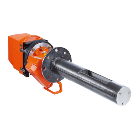
SICK GM32 Series Manual

TECHNICAL INFORMATION
GM32
In-situ Gas Analyzer
Measuring Probe Version
Title Page
These Instructions are intended exclusively
for trained personnel.
Unauthorized intervention voids the
manufacturer's warranty.
Operating for Service Technicians
Technical Details

2 GM32 · Technical information · 8011923 · V 1.4 · © SICK AG
Document Information
Described Product
Product name: GM32
Variants: GM32 Probe (measuring probe)
Document ID
Title: Technical Information GM32
Part No.: 8011923
Version: 1.4
Release: 2013-11
Manufacturer
SICK AG
Erwin-Sick-Str. 1 · D-79183 Waldkirch · Germany
Phone: +49 7641 469-0
Fax: +49 7641 469-1149
E-mail: info.pa@sick.de
Original Documents
The English edition 8011923 of this document is an original
document from SICK AG.
SICK AG assumes no liability for the correctness of an
unauthorized translation.
Contact SICK AG or your local representative in case of doubt.
Legal Information
Subject to change without notice.
© SICK AG. All rights reserved.

GM32 · Technical information · 8011923 · V 1.4 · © SICK AG 3
Warning Symbols
Warning Levels / Signal Words
DANGER
Risk or hazardous situation which will result in severe personal
injury or death.
WARNING
Risk or hazardous situation which could result in severe personal
injury or death.
CAUTION
Hazard or unsafe practice which could result in personal injury or
property damage.
NOTICE
Hazard which could result in material damage.
Information Symbols
Hazard (general)
Hazard by voltage
Hazard by unhealthy substances
Important technical information for this device
Important information on electric or electronic func-
tions
Supplementary information
Link to information at another place

Contents
4 GM32 · Technical information · 8011923 · V 1.4 · © SICK AG
1 General Information . . . . . . . . . . . . . . . . . . . . . . . . . . . . . . . . . . . . . . . . . . . . . . . . . . 7
1.1 Responsibility of user. . . . . . . . . . . . . . . . . . . . . . . . . . . . . . . . . . . . . . . . . . . . . . . . . . . . . . . . . 8
1.1.1 Designated users . . . . . . . . . . . . . . . . . . . . . . . . . . . . . . . . . . . . . . . . . . . . . . . . . . . . . . . . . . 8
1.1.2 Special local conditions . . . . . . . . . . . . . . . . . . . . . . . . . . . . . . . . . . . . . . . . . . . . . . . . . . . . 8
2 Product Description (Details). . . . . . . . . . . . . . . . . . . . . . . . . . . . . . . . . . . . . . . 9
2.1 Measuring method . . . . . . . . . . . . . . . . . . . . . . . . . . . . . . . . . . . . . . . . . . . . . . . . . . . . . . . . . . 10
2.1.1 Optics layout and functional principle . . . . . . . . . . . . . . . . . . . . . . . . . . . . . . . . . . . . . . . 10
2.2 Signal evaluation. . . . . . . . . . . . . . . . . . . . . . . . . . . . . . . . . . . . . . . . . . . . . . . . . . . . . . . . . . . . 11
2.3 Zero adjust (description) . . . . . . . . . . . . . . . . . . . . . . . . . . . . . . . . . . . . . . . . . . . . . . . . . . . . . 12
2.4 Reference cycle (description). . . . . . . . . . . . . . . . . . . . . . . . . . . . . . . . . . . . . . . . . . . . . . . . . 12
2.4.1 Reference cycle sequence . . . . . . . . . . . . . . . . . . . . . . . . . . . . . . . . . . . . . . . . . . . . . . . . . 12
2.5 Check cycle (description) . . . . . . . . . . . . . . . . . . . . . . . . . . . . . . . . . . . . . . . . . . . . . . . . . . . . 12
2.5.1 Control elements . . . . . . . . . . . . . . . . . . . . . . . . . . . . . . . . . . . . . . . . . . . . . . . . . . . . . . . . . 12
2.5.2 Check cycle (function) . . . . . . . . . . . . . . . . . . . . . . . . . . . . . . . . . . . . . . . . . . . . . . . . . . . . . 13
2.5.2.1 Wavelength scale monitoring . . . . . . . . . . . . . . . . . . . . . . . . . . . . . . . . . . . . . . . . . . . 13
2.5.2.2 Resolution drift monitoring . . . . . . . . . . . . . . . . . . . . . . . . . . . . . . . . . . . . . . . . . . . . . 13
2.5.2.3 Absorption drift monitoring . . . . . . . . . . . . . . . . . . . . . . . . . . . . . . . . . . . . . . . . . . . . . 13
2.5.2.4 Determining the zero and reference point . . . . . . . . . . . . . . . . . . . . . . . . . . . . . . . . 14
2.5.2.5 Monitoring the cell NO filling . . . . . . . . . . . . . . . . . . . . . . . . . . . . . . . . . . . . . . . . . . . . 14
2.5.2.6 Summary . . . . . . . . . . . . . . . . . . . . . . . . . . . . . . . . . . . . . . . . . . . . . . . . . . . . . . . . . . . . . 15
2.5.3 Events and signals output . . . . . . . . . . . . . . . . . . . . . . . . . . . . . . . . . . . . . . . . . . . . . . . . . 15
2.5.3.1 Check cycle signals . . . . . . . . . . . . . . . . . . . . . . . . . . . . . . . . . . . . . . . . . . . . . . . . . . . . 15
2.5.3.2 Maintenance request signal . . . . . . . . . . . . . . . . . . . . . . . . . . . . . . . . . . . . . . . . . . . . 15
2.5.3.3 Zero and reference point level output. . . . . . . . . . . . . . . . . . . . . . . . . . . . . . . . . . . . 15
2.6 Contamination compensation . . . . . . . . . . . . . . . . . . . . . . . . . . . . . . . . . . . . . . . . . . . . . . . . 16
2.6.1 Monitoring contamination . . . . . . . . . . . . . . . . . . . . . . . . . . . . . . . . . . . . . . . . . . . . . . . . . 16
2.7 Automatic adjustment with alignment . . . . . . . . . . . . . . . . . . . . . . . . . . . . . . . . . . . . . . . . . 16
2.8 Measuring probe in detail . . . . . . . . . . . . . . . . . . . . . . . . . . . . . . . . . . . . . . . . . . . . . . . . . . . . 17
Contents

Contents
GM32 · Technical information · 8011923 · V 1.4 · © SICK AG 5
3 CAN Connection. . . . . . . . . . . . . . . . . . . . . . . . . . . . . . . . . . . . . . . . . . . . . . . . . . . . . . . 21
3.1 GM32 CAN connection . . . . . . . . . . . . . . . . . . . . . . . . . . . . . . . . . . . . . . . . . . . . . . . . . . . . . . . 22
3.2 SCU connection (overview) . . . . . . . . . . . . . . . . . . . . . . . . . . . . . . . . . . . . . . . . . . . . . . . . . . . 23
3.3 Connecting the GM32 to the CAN bus and to the SCU . . . . . . . . . . . . . . . . . . . . . . . . . . . 24
3.3.1 Settings in GM32 . . . . . . . . . . . . . . . . . . . . . . . . . . . . . . . . . . . . . . . . . . . . . . . . . . . . . . . . . 25
3.3.2 Settings in the SCU. . . . . . . . . . . . . . . . . . . . . . . . . . . . . . . . . . . . . . . . . . . . . . . . . . . . . . . . 25
3.4 Mapping Table . . . . . . . . . . . . . . . . . . . . . . . . . . . . . . . . . . . . . . . . . . . . . . . . . . . . . . . . . . . . . . 26
4 Operation (Specialist Menus) . . . . . . . . . . . . . . . . . . . . . . . . . . . . . . . . . . . . . . 29
4.1 SOPAS ET (description). . . . . . . . . . . . . . . . . . . . . . . . . . . . . . . . . . . . . . . . . . . . . . . . . . . . . . . 30
4.2 Menu tree (in SOPAS ET) . . . . . . . . . . . . . . . . . . . . . . . . . . . . . . . . . . . . . . . . . . . . . . . . . . . . . 31
4.2.1 Changing the user level. . . . . . . . . . . . . . . . . . . . . . . . . . . . . . . . . . . . . . . . . . . . . . . . . . . . 32
4.2.2 Measured values. . . . . . . . . . . . . . . . . . . . . . . . . . . . . . . . . . . . . . . . . . . . . . . . . . . . . . . . . . 33
4.2.2.1 Bargraph measured values . . . . . . . . . . . . . . . . . . . . . . . . . . . . . . . . . . . . . . . . . . . . . 33
4.2.3 Parameters. . . . . . . . . . . . . . . . . . . . . . . . . . . . . . . . . . . . . . . . . . . . . . . . . . . . . . . . . . . . . . . 34
4.2.3.1 Device parameters . . . . . . . . . . . . . . . . . . . . . . . . . . . . . . . . . . . . . . . . . . . . . . . . . . . . . 34
4.2.3.2 Spectrometer . . . . . . . . . . . . . . . . . . . . . . . . . . . . . . . . . . . . . . . . . . . . . . . . . . . . . . . . . . 35
4.2.3.3 Coefficients . . . . . . . . . . . . . . . . . . . . . . . . . . . . . . . . . . . . . . . . . . . . . . . . . . . . . . . . . . . 35
4.2.3.4 Coefficients boxmeasuring . . . . . . . . . . . . . . . . . . . . . . . . . . . . . . . . . . . . . . . . . . . . . . 36
4.2.3.5 Adjustment sensor . . . . . . . . . . . . . . . . . . . . . . . . . . . . . . . . . . . . . . . . . . . . . . . . . . . . . 36
4.2.3.6 Logbook. . . . . . . . . . . . . . . . . . . . . . . . . . . . . . . . . . . . . . . . . . . . . . . . . . . . . . . . . . . . . . . 37
4.2.3.7 Analog outputs . . . . . . . . . . . . . . . . . . . . . . . . . . . . . . . . . . . . . . . . . . . . . . . . . . . . . . . . 38
4.2.3.8 Analog inputs . . . . . . . . . . . . . . . . . . . . . . . . . . . . . . . . . . . . . . . . . . . . . . . . . . . . . . . . . . 38
4.2.3.9 Digital inputs . . . . . . . . . . . . . . . . . . . . . . . . . . . . . . . . . . . . . . . . . . . . . . . . . . . . . . . . . . 39
4.2.3.10 Digital outputs . . . . . . . . . . . . . . . . . . . . . . . . . . . . . . . . . . . . . . . . . . . . . . . . . . . . . . . . . 39
4.2.3.11 Hardware Map . . . . . . . . . . . . . . . . . . . . . . . . . . . . . . . . . . . . . . . . . . . . . . . . . . . . . . . . . 41
4.2.4 Adjustment . . . . . . . . . . . . . . . . . . . . . . . . . . . . . . . . . . . . . . . . . . . . . . . . . . . . . . . . . . . . . . . 42
4.2.4.1 Alignment . . . . . . . . . . . . . . . . . . . . . . . . . . . . . . . . . . . . . . . . . . . . . . . . . . . . . . . . . . . . . 42
4.2.4.2 Zero adjust (Service level only) . . . . . . . . . . . . . . . . . . . . . . . . . . . . . . . . . . . . . . . . . . 43
4.2.4.3 Boxmeasuring (Service level only) . . . . . . . . . . . . . . . . . . . . . . . . . . . . . . . . . . . . . . . 44
4.2.5 Diagnosis . . . . . . . . . . . . . . . . . . . . . . . . . . . . . . . . . . . . . . . . . . . . . . . . . . . . . . . . . . . . . . . .45
4.2.5.1 Device information . . . . . . . . . . . . . . . . . . . . . . . . . . . . . . . . . . . . . . . . . . . . . . . . . . . . . 45
4.2.5.2 Logbook. . . . . . . . . . . . . . . . . . . . . . . . . . . . . . . . . . . . . . . . . . . . . . . . . . . . . . . . . . . . . . . 45
4.2.5.3 Check cycle . . . . . . . . . . . . . . . . . . . . . . . . . . . . . . . . . . . . . . . . . . . . . . . . . . . . . . . . . . . 47
4.2.5.4 Sensor values . . . . . . . . . . . . . . . . . . . . . . . . . . . . . . . . . . . . . . . . . . . . . . . . . . . . . . . . . 47
4.2.5.5 Temperature unit . . . . . . . . . . . . . . . . . . . . . . . . . . . . . . . . . . . . . . . . . . . . . . . . . . . . . . 50
4.2.5.6 Spectra . . . . . . . . . . . . . . . . . . . . . . . . . . . . . . . . . . . . . . . . . . . . . . . . . . . . . . . . . . . . . . . 51
4.2.6 Maintenance . . . . . . . . . . . . . . . . . . . . . . . . . . . . . . . . . . . . . . . . . . . . . . . . . . . . . . . . . . . . . 56
4.2.6.1 Operating mode switch . . . . . . . . . . . . . . . . . . . . . . . . . . . . . . . . . . . . . . . . . . . . . . . . . 56
4.2.6.2 Lamp hour meter . . . . . . . . . . . . . . . . . . . . . . . . . . . . . . . . . . . . . . . . . . . . . . . . . . . . . . 56
4.2.6.3 Save EEPROM . . . . . . . . . . . . . . . . . . . . . . . . . . . . . . . . . . . . . . . . . . . . . . . . . . . . . . . . . 57
4.2.6.4 Load EEPROM . . . . . . . . . . . . . . . . . . . . . . . . . . . . . . . . . . . . . . . . . . . . . . . . . . . . . . . . . 57
4.2.7 Start-up Assistant . . . . . . . . . . . . . . . . . . . . . . . . . . . . . . . . . . . . . . . . . . . . . . . . . . . . . . . . . 57

Contents
6 GM32 · Technical information · 8011923 · V 1.4 · © SICK AG
4.3 Program/data structure (“Firmware”, “Device description file”) . . . . . . . . . . . . . . . . . . 58
4.3.1 Sequence of settings and file transfers . . . . . . . . . . . . . . . . . . . . . . . . . . . . . . . . . . . . . 58
4.3.2 Setting the GM32 analyzer/SCU IP address . . . . . . . . . . . . . . . . . . . . . . . . . . . . . . . . . 59
4.3.3 Updating the firmware (GM32 analyzer/SCU) . . . . . . . . . . . . . . . . . . . . . . . . . . . . . . . . 60
4.3.4 Loading the device description file (“Make available to SOPAS ET”) . . . . . . . . . . . . 61
4.3.5 Saving and loading parameters (device data). . . . . . . . . . . . . . . . . . . . . . . . . . . . . . . . 62
4.3.5.1 Loading parameters changed in SOPAS ET to the GM32 analyzer/SCU . . . . . . 62
4.3.5.2 Saving parameters (GM32 analyzer/SCU) to an external data medium . . . . . . 63
4.3.5.3 Loading parameters from an external data medium to the GM32 analyzer/
SCU . . . . . . . . . . . . . . . . . . . . . . . . . . . . . . . . . . . . . . . . . . . . . . . . . . . . . . . . . . . . . . . . . . 63
4.3.6 Loading data files from the device. . . . . . . . . . . . . . . . . . . . . . . . . . . . . . . . . . . . . . . . . . 63
5 Maintenance . . . . . . . . . . . . . . . . . . . . . . . . . . . . . . . . . . . . . . . . . . . . . . . . . . . . . . . . . . 65
5.1 Zero adjust (zero point check) . . . . . . . . . . . . . . . . . . . . . . . . . . . . . . . . . . . . . . . . . . . . . . . . 66
5.1.1 Procedure. . . . . . . . . . . . . . . . . . . . . . . . . . . . . . . . . . . . . . . . . . . . . . . . . . . . . . . . . . . . . . . . 66
5.2 Boxmeasuring . . . . . . . . . . . . . . . . . . . . . . . . . . . . . . . . . . . . . . . . . . . . . . . . . . . . . . . . . . . . . . 68
5.2.1 Preparing the filter box . . . . . . . . . . . . . . . . . . . . . . . . . . . . . . . . . . . . . . . . . . . . . . . . . . . . 69
5.2.2 Determining the necessary test gas concentration . . . . . . . . . . . . . . . . . . . . . . . . . . . 71
5.2.3 Procedure. . . . . . . . . . . . . . . . . . . . . . . . . . . . . . . . . . . . . . . . . . . . . . . . . . . . . . . . . . . . . . . . 72
5.3 Test gas feeding (for GPP measuring probe) . . . . . . . . . . . . . . . . . . . . . . . . . . . . . . . . . . . 76
5.3.1 One-off initial measurement - determining the test gas pressure . . . . . . . . . . . . . . 77
5.3.2 Manual test gas feeding . . . . . . . . . . . . . . . . . . . . . . . . . . . . . . . . . . . . . . . . . . . . . . . . . . . 78
5.3.3 Using mixed gases as test gases . . . . . . . . . . . . . . . . . . . . . . . . . . . . . . . . . . . . . . . . . . . 78
5.4 Fitting and removing the power supply unit of the connection unit . . . . . . . . . . . . . . . 79
6 Shutting down/Restarting . . . . . . . . . . . . . . . . . . . . . . . . . . . . . . . . . . . . . . . . . 81
6.1 Qualification requirements . . . . . . . . . . . . . . . . . . . . . . . . . . . . . . . . . . . . . . . . . . . . . . . . . . . 82
6.2 Shutting down . . . . . . . . . . . . . . . . . . . . . . . . . . . . . . . . . . . . . . . . . . . . . . . . . . . . . . . . . . . . . . 82
6.2.1 Equipment required . . . . . . . . . . . . . . . . . . . . . . . . . . . . . . . . . . . . . . . . . . . . . . . . . . . . . . . 82
6.2.2 Shutdown . . . . . . . . . . . . . . . . . . . . . . . . . . . . . . . . . . . . . . . . . . . . . . . . . . . . . . . . . . . . . . . . 83
6.2.2.1 Removing from the sample gas duct. . . . . . . . . . . . . . . . . . . . . . . . . . . . . . . . . . . . . 83
6.2.3 Disconnecting the purge air connection . . . . . . . . . . . . . . . . . . . . . . . . . . . . . . . . . . . . . 84
6.2.4 Putting the purge air unit out of operation. . . . . . . . . . . . . . . . . . . . . . . . . . . . . . . . . . . 85
6.3 Further components on the measuring point . . . . . . . . . . . . . . . . . . . . . . . . . . . . . . . . . . . 86
6.3.1 Connection unit and cabling . . . . . . . . . . . . . . . . . . . . . . . . . . . . . . . . . . . . . . . . . . . . . . . 86
6.4 Conservation measures, correct storage and transport . . . . . . . . . . . . . . . . . . . . . . . . . 87
6.5 Preparing for restarting . . . . . . . . . . . . . . . . . . . . . . . . . . . . . . . . . . . . . . . . . . . . . . . . . . . . . . 89
6.5.1 New measuring task . . . . . . . . . . . . . . . . . . . . . . . . . . . . . . . . . . . . . . . . . . . . . . . . . . . . . . 89
6.5.2 Previous measuring task . . . . . . . . . . . . . . . . . . . . . . . . . . . . . . . . . . . . . . . . . . . . . . . . . . 89
6.5.3 Purge air unit maintenance . . . . . . . . . . . . . . . . . . . . . . . . . . . . . . . . . . . . . . . . . . . . . . . . 89
7 Annex . . . . . . . . . . . . . . . . . . . . . . . . . . . . . . . . . . . . . . . . . . . . . . . . . . . . . . . . . . . . . . . . . . . 91
7.1 Commissioning checklist. . . . . . . . . . . . . . . . . . . . . . . . . . . . . . . . . . . . . . . . . . . . . . . . . . . . . 92

General Information
GM32 · Technical information · 8011923 · V 1.4 · © SICK AG 7
Subject to change without notice
GM32
1General Information
Responsibility of user

8 GM32 · Technical information · 8011923 · V 1.4 · © SICK AG
General Information
Subject to change without notice
1.1 Responsibility of user
1.1.1 Designated users
This Technical Information is aimed at qualified persons familiar with the GM32 and who,
based on their device-specific training and knowledge of the device as well as knowledge
of the relevant regulations, can assess the tasks given and recognize the dangers involved.
1.1.2 Special local conditions
Follow all local laws, regulations and company-internal operating directives applicable at
the installation location.

Product Description (Details)
GM32 · Technical information · 8011923 · V 1.4 · © SICK AG 9
Subject to change without notice
GM32
2Product Description (Details)
Functional principle
Check cycles
Remote operation

10 GM32 · Technical information · 8011923 · V 1.4 · © SICK AG
Product Description (Details)
Subject to change without notice
2.1 Measuring method
2.1.1 Optics layout and functional principle
The GM32 multi-component analyzer is based on in-situ technology with opto-electronic
direct measurement. Measured values are recorded without contact directly in the gas flow
using a measuring probe protruding into the duct. Depending on the version, this has
either an open measuring gap or a gas permeable membrane insert (filter) through which
the gas mixture being measured flows - the active measuring path.
The GM32 SR-unit determines the concentration of the respective gases based on wave-
length-specific light absorption by the gas mixture in the active measuring path.
Light from the sender/receiver unit (SR-unit) illuminates the active measuring path in the
gas duct which is then reflected back again by a triple reflector at the end of the probe. The
beam splitter diverts the returning light to the polychromatic subassembly comprising a
condenser lens with slit diaphragm, optical grating and receiver element. The optical
grating dissects the returning light spectrally and maps it to the receiver element, a highly
sensitive diode array.
Fig. 1 Measuring principle
1 Emitter
2 Tracking mirror
3 Window
4 Reflector
5 Beam splitter
6 4-quadrants detector
7 Optical grating
8 Detector
1A
2
8
55
4
B
A Swivel segment with filter and cell for check cycles
B Swivel segment with zero point reflector and blanking diaphragm
3
7
6

Product Description (Details)
GM32 · Technical information · 8011923 · V 1.4 · © SICK AG 11
Subject to change without notice
2.2 Signal evaluation
The optimized algorithms of the GM32 evaluation electronics process the measurement
signal of the receiver element together with the associated parameters according to the
DOAS (Differential Optical Absorption Spectroscopy) method.
Fig. 2 Absorption spectra from sample gases (schematic)
The method is based on the physical capability of gas molecules to absorb light energy in
the typical wavelength ranges for the respective types of gas. Spectral dissection in the
receiver element captures the absorption of gas molecules at characteristic points of the
spectrum in the IR wavelength range 200 to 400 nm. Corresponding sections within this
range are evaluated depending on the device type. The optimized algorithms used here
ensure concentrations of gas components searched for are determined without cross-
sensitivity to other gases. To do this, the respective evaluation IR range for the components
to be measured is defined so that no “foreign gases” disturb the spectrum structure.

12 GM32 · Technical information · 8011923 · V 1.4 · © SICK AG
Product Description (Details)
Subject to change without notice
2.3 Zero adjust (description)
Zero adjust basically fulfills two tasks:
●Adjustment of the device in the measuring path
●Determination of reference values for check cycles
●Zero adjust is started manually (
p. 66, §5.1)
2.4 Reference cycle (description)
The reference cycle serves to compensate changes in lamp intensity (e.g. through aging)
and contamination effects in the SR-unit.
The measured concentration values are retained (e.g. on analog outputs) during the refer-
ence cycle.
The reference cycle interval is adjustable (
p. 34, §4.2.3.1).
2.4.1 Reference cycle sequence
1Determining the spectrometer offset
2Setting the lamp parameters
3Determining the aperture signal (dark signal)
4Determining the reference spectrum
5Determining the 4Q offset
2.5 Check cycle (description)
The check cycle serves to check the zero and reference point for each component without
using test gases.
The check cycle meets the requirements of EN14181 and obviates “drift monitoring with
test gases” according to QAL3.
The check cycle interval is adjustable (
p. 34, §4.2.3.1).
2.5.1 Control elements
Control elements that can be swiveled in are used for measuring during the check:
●2 grating filters:
– Grating filter 1: Finely woven grating with 51% transmission and 0.3 absorption
– Grating filter 2: Finely woven grating with 6.3% transmission and 1.2 absorption
●NO cell:
–Activelength5mm
– Filling 20% NO in N2
–Singlebeampath
Relative to the double beam path used in measuring operation, this gives a C x L of
approx. 500 ppm x m or 600 mg/m³ x m
●1 zero point reflector

Product Description (Details)
GM32 · Technical information · 8011923 · V 1.4 · © SICK AG 13
Subject to change without notice
2.5.2 Check cycle (function)
The following influencing factors are the main cause of drifts in concentration measure-
ment:
●Wavelength scale drift
●Spectral resolution drift
●Absorption drift
Methods to monitor these influencing factors are described in the following.
2.5.2.1 Wavelength scale monitoring
The grating spectrometer used in the GM32 shows, due to the design, wavelength scale
drifts caused by mechanical effects (e.g. length changes caused by temperature fluctua-
tions). Compensation is realized through continuous determination of this drift during
measuring operation and calculation back to the original state through numeric interpola-
tion.
Wavelength drift is monitored in two stages during the check cycle:
1Determining the position of an NO absorption line ensures correct functioning of wave-
length drift compensation.
To do this, a spectrum is examined with the NO cell swiveled in and the line position
deviation calculated as compared against the original device state.
A maintenance request is signaled when this deviation exceeds a limit value (normally
0.046 nm)
2The overall wavelength drift is checked relative to the original device state. A mainte-
nance request is also signaled here when a limit value (normally 1 mm) is exceeded.
These measures ensure wavelength drift is compensated correctly and therefore has no
influence on measured values.
2.5.2.2 Resolution drift monitoring
Spectral resolution of the grating spectrometer used can change during operation due to
mechanical changes or contamination (scattered light). Resolution deterioration normally
leads to a reduction in sensitivity and the device displays values that are too low.
This is why the spectral resolution is examined during the check cycle.
To do this, the half-width of an NO absorption line is calculated from the NO cell spectrum
(see above).
A maintenance request is signaled when this deviation exceeds a limit value (normally
0.035 nm) as compared against the original state.
This check ensures resolution changes are detected before device sensitivity changes sig-
nificantly.
2.5.2.3 Absorption drift monitoring
Measured values output by the device have, to a large extent, a linear association with the
measured absorption. The consequence is that errors during absorption measurement
have a direct effect on measured values. Possible error sources for absorption determina-
tion are fluctuating scattered light intensities in the device as well as erroneous determina-
tion of the dark current of the detector array.
Two grating filters that serve as standard are used to check absorption determination. The
absorption for each of the two filters is determined during the check cycle and compared
against the values in original state. The deviations for both filters are averaged and this
value checked against a limit value (normally 2% of the measured value). A maintenance
request is signaled when the limit value is exceeded.

14 GM32 · Technical information · 8011923 · V 1.4 · © SICK AG
Product Description (Details)
Subject to change without notice
2.5.2.4 Determining the zero and reference point
The zero point is determined by creating a zero spectrum by swiveling in a zero point reflec-
tor during the check cycle. This spectrum corresponds to measurement with a measuring
path free from gas.
Based on this zero spectrum and using the device calibration function, the associated
measured concentration values for individual components are determined and output.
A maintenance request is signaled when one of these zero values exceeds a limit value
(normally 2% of the FS).
The absorption measurement deviation determined above is used to calculate the refer-
ence value. The value
is output as reference value for all components.
As described above, there are three causes for reference point drift:
●Wavelength scale drift
●Resolution drift
●Absorption drift
The measures described in
§2.5.2.1 and
§2.5.2.2 keep the first two drift causes within
very strict limits. This is why the value rp gained from absorption measurement is represen-
tative for reference point drift for all measuring components.
2.5.2.5 Monitoring the cell NO filling
The check cycle only runs correctly when the NO cell filling is sufficient.
Determining a value for an NO absorption line serves to monitor the cell concentration.
A maintenance request is signaled when the value sinks below 0.1 absorption units.
rp (70%+[Absorption deviation in %]) FS=

Product Description (Details)
GM32 · Technical information · 8011923 · V 1.4 · © SICK AG 15
Subject to change without notice
2.5.2.6 Summary
2.5.3 Events and signals output
2.5.3.1 Check cycle signals
The Not_measuring signal is active during the check cycle.
This signal can be sent via a digital output or read out via the OPC interface.
2.5.3.2 Maintenance request signal
The Maintenance_request signal is activated when an unallowed drift is determined or the
NO cell is empty
p. 13, §2.5.2) and, at the same time, an appropriate message entered in
the Logbook. The Maintenance_request signal can be sent via a digital output or read out
via the OPC interface.
2.5.3.3 Zero and reference point level output
The zero and reference point values determined can be output via the analog outputs. This
is done - depending on the parameter settings - directly after the check cycle or on demand
(via a digital input). The Output_control_values signal is active during output and can also
be sent via a digital output. The zero values are first output for 90 s and then the reference
values for 90 s. The Not_measuring signal is not active during the output.
As an alternative, the zero and reference values of the last check cycle can be read out
using SOPAS ET menu /Diagnosis/Check cycle.
Table 1 Evaluation of data determined during the check cycle
Purpose Data used Evaluation Resulting action
1Checkwave-
length scale over-
all drift
Current wave-
length scale
Determine shift of
wavelength scale
against scaling
Maintenance request signal when
shift above limit
2Checkwave-
length drift
compensation
NO spectrum Determine NO peak
position
Maintenance request signal when
deviation from value against
scaling over limit
3 Check resolution NO spectrum Determine NO peak
width
Maintenance request signal when
deviation from value against
scaling over limit
4 Checkabsorption
scale
Grating filter spec-
tra
Grating filter absorp-
tion change relative to
scaling
Control value1output for individ-
ual components.
Maintenance request signal when
deviation from nominal value over
limit
1Control value calculated as (70%+ grating absorption deviation in %) x FS
5 Check zero point Zero spectrum Evaluate zero spec-
trum with calibration
function
Zero value output for individual
components
Maintenance request signal when
deviation from zero over limit
6 Check cell filling NO spectrum Determine NO peak
height
Maintenance request signal when
peak height under 0.1 absorption
units

16 GM32 · Technical information · 8011923 · V 1.4 · © SICK AG
Product Description (Details)
Subject to change without notice
2.6 Contamination compensation
During the reference cycle, the zero point reflector serves to compensate contamination
occurring in the SR-unit. Contamination of the front window or measurement reflector
cannot be compensated in this manner. Light absorption also occurs during measuring
operation through dust in the flue gas. Both of these effects cannot be determined sepa-
rately due to the principle used and are compensated together using a basic line correction
during spectrum evaluation (
p. 11, §2.2).
2.6.1 Monitoring contamination
As described above, contamination outside the SR-unit cannot be differentiated from dust
effects. However, both effects are monitored together by continuous control of the maxi-
mum absorption measured in the spectral range of the evaluation. A maintenance request
is signaled when this absorption rises above a warning value that can be set as a parame-
ter (standard: absorption 1.8). Failure is signaled when a limit value is exceeded (standard
absorption 2.0).
2.7 Automatic adjustment with alignment
Swivel movements of the reflector relative to the SR-unit can occur during measuring oper-
ation. This can be caused, for example, when the probe bends due to varying gas tempera-
tures. These swivel movements are compensated continually on the GM32 by the built-in
tracking mirror. Motors tilt this mirror in two directions and can thereby compensate
occurring swivel movements.

Product Description (Details)
GM32 · Technical information · 8011923 · V 1.4 · © SICK AG 17
Subject to change without notice
2.8 Measuring probe in detail
Fig. 3 GPP measuring probe with ceramic filter and ceramic/teflon filter
Integrated sensors
All probe versions have a built-in pressure sensor as well as an integrated temperature
sensor PT 1000 that continually measures the medium temperature of the probe in the
active measuring path.
The measured data are transmitted via the CAN bus interface of the measuring probe.
EPA conformity
When using a GPP probe/EPA probe, an audit measurement conforming to EPA CFR 40
Part 60 and/or Part 75 can be carried out with the device fitted.

18 GM32 · Technical information · 8011923 · V 1.4 · © SICK AG
Product Description (Details)
Subject to change without notice
GMP probe with open measuring gap
Shortest reaction times and high temperature stability characterize the GMP series
measuring probes. Continuous purge air feed is required for operation. The air outlet runs
in the duct offset 90° to the gas flow (Directed Purge Air).
The GMP probe has a locking device on the opening for sample gas that is activated with a
lever on the probe flange.
Fig. 4 GMP measuring probe (with open measuring gap)
Temperature sensor
PT 1000
Purge air outlet
Open measuring
path (measuring
gap)
Lever position
Lever and locking device:
Open

Product Description (Details)
GM32 · Technical information · 8011923 · V 1.4 · © SICK AG 19
Subject to change without notice
GPP – gas diffusion probe in dry or wet version
This version is more suitable for higher dust contents because, on GPP probes, dust parti-
cles are separated on the filter element and therefore kept away from the measuring path.
To allow an EPA-conform audit measurement as well as with low flow speeds or irregular
flow profiles, the GPP (Gas Permeable Probe) should also be chosen.
Fig. 5 Measuring gap of the GPP measuring probe
Both variants of the GPP differ in the respective filter which provides suitability for different
application areas.
They are fitted with an automatically controlled heater to reliably prevent condensate on
the optical interfaces.
The heating control is located between the assembly and device flange in a housing
connected firmly with the probe. The electronics for heating control and temperature and
pressure measurement are protected safely in a stable cast housing that forms the section
of the measuring probe between the duct flange and SR-unit. Both the electrical connec-
tions for CAN bus and power supply as well as the test gas connection and pressure
measurement connection are fitted on this housing and serve manual activation of the
audit measurement according to EPA Guideline CFR 40, Part 60 or Part 75.
Temperature sensor PT 1000
Ceramic filter or teflon/ceramic
filter, gas permeable

20 GM32 · Technical information · 8011923 · V 1.4 · © SICK AG
Product Description (Details)
Subject to change without notice
Other manuals for GM32 Series
3
Table of contents
Other SICK Measuring Instrument manuals

SICK
SICK DEFOR Operating instructions

SICK
SICK FLOWSIC200 User manual

SICK
SICK T-EASIC FTS User manual

SICK
SICK Lector85x User manual

SICK
SICK Lector63x Flex C-mount User manual

SICK
SICK FWE200DH User manual

SICK
SICK VMS410 User manual

SICK
SICK SIM1004 User manual

SICK
SICK FLOWSIC500 User manual

SICK
SICK MLG-2 Prime User manual

SICK
SICK PGT-09-S User manual

SICK
SICK DL100 Pro User manual

SICK
SICK HTF18 User manual

SICK
SICK GM901 User manual

SICK
SICK GM700 User manual

SICK
SICK FLOWSIC600 User manual

SICK
SICK NAV200 User manual

SICK
SICK GM700 User manual

SICK
SICK FLOWSIC100 Flare-XT User manual

SICK
SICK microScan3 Pro I/O User manual