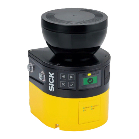
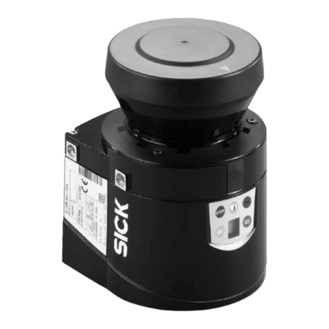
SICK LMS 200 Parts list manual

T
ECHNICAL
D
ESCRIPTION
LMS 200 / LMS 211 /
LMS 220 / LMS 221 / LMS 291
Laser Measurement Systems

Technical Description
LMS 2… Laser Measurement System
© SICK AG · Division Auto I ent · Germany · All rights reserve 8 008 970/06-2003
2
Contents
Contents
1 Range of applications ...................................................................................................................... 3
2 Product features ................................................................................................................................. 4
3 Operating principle ............................................................................................................................ 6
4 Conditions of use/range ................................................................................................................. 7
4.1 Mounting location ....................................................................................................................... 7
4.2 Heater operation ........................................................................................................................ 7
4.3 Reflectivity of various objects ................................................................................................ 7
4.4 Reflectivity in fog ......................................................................................................................... 8
4.5 The „blanking“ curve ................................................................................................................. 9
4.6 The „contour as reference“ curve ........................................................................................ 9
5 Areas of use ...................................................................................................................................... 10
5.1 Object measurement/ etermining position ................................................................... 10
5.2 Area monitoring/Detection .................................................................................................. 11
6 ounting ............................................................................................................................................ 12
7 L S 211/L S 220/L S 221 electrical installation ...................................................... 14
7.1 Data interface ........................................................................................................................... 14
7.2 Power supply ............................................................................................................................ 14
7.3 Motor flap for the LMS 211 ................................................................................................ 15
7.4 LMS 211/LMS 221 electrical connection ..................................................................... 16
7.5 LMS 211/LMS 221 electrical connection with relay output.................................... 17
8 L S 200/L S 291 electrical installation ........................................................................... 18
8.1 Electrical connection ............................................................................................................. 18
8.2 Interface plugs (plug mo ules) ......................................................................................... 18
8.3 LMS 200/LMS 291 electrical connection.................................................................... 19
8.3.1 RS 232/RS 422-conversion ........................................................................... 19
8.3.2 Cable entry in plug mo ule .............................................................................. 20
8.3.3 Functions of the in icator lights ..................................................................... 20
9 Synchronisation of two laser scanners .................................................................................. 21
9.1 Pre-con itions for synchronisation .................................................................................... 21
9.2 Proce ure ................................................................................................................................... 21
9.3 Commissioning synchronisation ........................................................................................ 22
10 Heating plate for the L S 200/L S 291 ........................................................................... 23
Weather protection for the L S 220/L S 221 ................................................................ 25
11 Dimensional drawings .................................................................................................................. 26
12 Overview of L S variants............................................................................................................ 33
13 Technical data .................................................................................................................................. 34
14 Order numbers ................................................................................................................................. 35
15 Glossary of terms ........................................................................................................................... 37
EC Declaration of Conformity ....................................................................................................38
Technical Description
LMS 2…
Chapter 1
© SICK AG · Division Auto Ident · German · All rights reserved8 008 970/06-2003 1
Range of applications
?
1Range of applications
•Determining the volumes or contours of bulk materials
•Determining the volumes of objects (measuring packages, pallets, containers)
•Determining the position of objects (pallets, containers, transport vessels)
•Collision prevention for vehicles or cranes
•Controlling docking processes (positioning)
•Classification of objects (vehicle detection, camera trigger)
•Process automation (e.g. calender rollers)
•Checking overhang/area monitoring in automated multi-store car parks
•Monitoring open spaces for building securit (facades, grounds, shafts)
•and man more
LMS 200, LMS 220,
LMS 211, LMS 221, LMS 291
Laser Measurement Systems
Fig. 1-1: Collision prevention on container cranes Fig. 1-2: Measuring bulk materials on conve or belts or
in bunkers
Fig. 1-3: Monitoring open spaces for building securit
Fig. 1-4: Collision prevention Fig. 1-5: Collision prevention at the harbour Fig. 1-6: Detection of objects
Fig. 1-7: Classification of vehicles Fig. 1-9: Checking overhang in automated multi-store
car parks
3
Fig. 1-8: Your application
?
?
??
?
?

Technical Description
LMS 2… Laser Measurement System
Chapter 2
8 008 970/06-200
2
Product features
© SICK AG · Division Auto Ident · Germany · All rights reserved
2Product features
LMS 2.. laser scanners are non-contact measurement systems (NCSDs), that scan their
surroundings two-dimensionally (laser radio). As scanning systems the devices require
neither reflectors nor position marks.
The systems are used for:
•area monitoring
•object measurement and detection
•determining positions
Defined monitored fields can be programmed in the scanner for the area monitoring
application. Each monitored field is assigned a 24 V switching output.
The LMI interface module is available as an optional extension to the system. It can ad-
minister several scanners and provides the corresponding 24 V switching outputs.
Standard solutions are available for object measurement, e.g. measuring the volumes of
packages and pallets; volume flow measurement for bulk materials; etc.
The scanner’s measurement data can be individually processed in real time with exter-
nal evaluation software for determining positions and other measurement tasks.
Maintenance and care
The LMS scanner requires no maintenance, though depending on its location the scan-
ner’s front window should cleaned occasionally.
Please note:
Never open the laser scanner yourself! The producer warranty will be forfeited if the
scanner is opened.
Erroneous functions can be clarified by means of the LMS/LMI User Software error di-
agnosis. The SICK Service team is available for handling more serious errors.
Errors caused by a contaminated front window are indicated via the built-in LEDs (see
Table 8-1).
Please note:
LMS laser scanners are not devices for protectin persons as defined by current
machine safety standards.
4
!

Technical Description
LMS 2…
Chapter 2
© SICK AG · Division Auto Ident · Germany · All rights reserved8 008 970/06-200 3
Product features
Features and advanta es
•Non-contact optical measurement, even over longer distances
•Rapid scanning times, thus measurement objects can move at high speeds
•No special target-object reflective properties necessary
•No reflectors and no marking of the measurement objects necessary
•Backgrounds and surroundings do not have any influence on the measurements
•Measurement objects may be in any position
•Measurement data is available in real time and can be used for further processing
or control tasks
•Active system – no illumination of the measurement area required
•Simple mounting and commissioning
•Completely weatherproof variants
Fig. 2-1: LMS 200 Fig. 2-2: LMS 220
Fig. 2- : LMS 291 Fig. 2-4: LMS 221 Fig. 2-5: LMS 211
5
See also
12 Overview of
LMS variants

Technical Description
LMS 2… Laser Measurement System
Chapter 3
8 008 970/06-200
2
Operating principle
© SICK AG · Division Auto Ident · Germany · All rights reserved
3Operating principle
The LMS system operates by measuring the time of flight of laser light pulses: a pulsed
laser beam is emitted and reflected if it meets an object. The reflection is registered by
the scanner’s receiver. The time between transmission and reception of the impulse is
directly proportional to the distance between the scanner and the object (time of flight).
The pulsed laser beam is deflected by an internal rotating mirror so that a fan-shaped
scan is made of the surrounding area (laser radar). The contour of the target object is
determined from the sequence of impulses received. The measurement data is avail-
able in real time for further evaluation via a serial interface.
Automatic fog correction is active in the scanner for outdoor use. Raindrops and snow-
flakes are cut out using pixel-oriented evaluation.
Spot spacing/spot diameter/range
In a radial field of vision, a light impulse (spot) is emitted every 0.25°, 0.5° or 1°
(depending on the variant).
As a result of the beam geometry and the diameter of the individual spots, the spots
overlap on the target object or up to a certain distance. Fig. 3-2 shows spot spacing in
relation to the range and the corresponding spot diameter.
Fig. -2: Spot sizes/spot spacing
Fig. -1: Operating principle
Spot diameter
LMS 211/221/291
Spot diameter
LMS 200/220
Spot spacing for
angular resolution of 1°
6
Spot spacing for
angular resolution of 0.5°
Spot spacing for
angular resolution of 0.25°
Range [m]
Spot diameter/
spot spacing [cm]
02468101214
0
5
10
15
20
25
30
35
16 18 30
p[]
20 22 24 26 28

Technical Description
LMS 2…
Chapter 4
© SICK AG · Division Auto Ident · German · All rights reserved8 008 970/06-2003 1
Conditions of use/range
4Conditions of use/range
4.1 Mounting location
The scanner ma be installed in an position. The mounting instructions in Chapter 6 are
to be observed.
100
10
1
0,1 110
600
60
Fig. 4-1: LMS 200/LMS 220
Range in relation to object reflectivit
4.2 Heater operation (LMS 220 and LMS 211/LMS 221)
In order to be able to use the LMS at temperature ranges below 0° C, a thermostat-
controlled heater has been installed in these scanners and supplementar front window
heating in the LMS 211. The heating comes into operation at ≤ 10° C order to prevent
thawing within the housing.
Before commissioning the LMS (e.g. before starting work) the interior of the scanner
must be heated to at least 0° C and an ice on the front window must be melted.
The scanner takes approx. 120 min. to heat up at an outdoor temperature of –30° C.
Material Reflectivit
Cardboard, matt black 10%
Cardboard, gre 20%
Wood (raw pine, dirt ) 40%
PVC, gre 50%
Paper, matt white 80%
Aluminium, anodised, black 110…150%
Steel, rust-free shin 120…150%
Steel, ver shin 140…200%
Reflectors > 2000%
4.3 Reflectivit of various objects
The range of the scanner depends on the reflectivit of the target object and the trans-
mission strength of the scanner. Some reflectivit values for well-known materials have
been included below as an overview (KODAK standards).
LMS with high range and fog
correction:
LMS 211-30206
LMS 211-S07
LMS 221-30206
LMS 221-S07
LMS 291-S05
LMS 211-S12/S13/S14
LMS with standard range without fog
correction:
LMS 200-30106
LMS 220-30106
LMS 211-30106
Range [m]
Reflectivit [%]
7

Technical Description
LMS 2… Laser Measurement S stem
Chapter 4
8 008 970/06-2003
2
Conditions of use/range
© SICK AG · Division Auto Ident · German · All rights reserved
In exceptional cases, sensitivit can be changed with the user software provided:
•values for standard setting (see diagram): 30 m range/10% reflectivit
•values for less sensitive thresholds: 25 m range/10% reflectivit
•values for more sensitive thresholds: 30 m range/5% reflectivit
Please note:
Note the remission graph in the range 0 to 1,5 m for LMS 211/LMS 221/LMS 291.
Higher sensitivit improves detection capabilities for dark objects, but increases ambient
light sensitivit .
Lower sensitivit reduces detection capabilities for dark objects, but reduces ambient light
sensitivit .
Ref ectivity [%]
Range [m]
typ. ref ectivity at
nomina visibi ity
50 m
100 m
200 m
500 m
010
20
30
40
50
60
70
205 15 253035404550
10
0
80
90
100
55 60 65 70 75 80
Fig. 4-3: LMS 211 – relationship between reflectivit and range in fog
Ref ectivity [%]
Range [m]
010
20
30
40
50
60
70
205 15 253035404550
10
0
80
90
100
55 60 65 70 75 80
typ. Neugerät mit Verschmutzung (Warnsigna aktiv)LMS 211
LMS 211 typ. new device with c ean front window
LMS 221
LMS 291
typ. new device with c ean front window
LMS 221
LMS 291
typ. new device with po ution (warning signa active)
typ. new device with po ution (warning signa active)LMS 211
Fig. 4-2: LMS 211, LMS 221, LMS 291, relationship between reflectivit and range with good visibilit
4.4 Reflectivit in fog (LMS 211-30206/LMS 221-30206/LMS 291-S05)
Fig. 4-3 to Fig. 4-6 are valid should there be fog during outdoor operation and are to be
observed.
8

Technical Description
LMS 2…
Chapter 4
© SICK AG · Division Auto Ident · German · All rights reserved8 008 970/06-2003 3
Conditions of use/range
4.5 The „blanking“ curve (LMS Outdoor and LMI 400)
The object suppression software setting is dependent on distance. An object can onl be
suppressed up to a certain distance. Furthermore, the scanner switches independentl of
object size.
Fig. 4-5: Relationship between the usable range and the defined blanking diameter, e.g.
max. 17 m with the blanking diameter of 0.3 m.
Fig. 4-6: Relationship between the usable range and reliabl detected object diameter, e.g. the
LMS switches if it loses the contour in 17 m with a object diameter of 0.3 m.
Ref ectivity [%]
Range [m]
typ. ref ectivity at
nomina visibi ity
50 m
100 m
200 m
500 m
010
20
30
40
50
60
70
205 15 253035404550
10
0
80
90
100
55 60 65 70 75 80
Fig. 4-4: LMS 221/LMS 291 – relationship between reflectivit and range in fog
9
4.6 The „contour as reference“ curve (LMS Outdoor and LMI 400)
The contour as reference software setting is dependent on distance. The scanner requires
a minimum contour as reference depending on the distance. Loss of the contour will not be
switched at the switching output if the contour is too small.
0 0.2
10
15
20
25
30
0.40.1 0.3 0.5 0.6 0.7 0.8
5
0
Measurement distance [m]
0.9 1
LMS/LMI 400: angular resolution 1
Suppressible object diameter [m]
0 0.2
10
15
20
25
30
0.40.1 0.3 0.5 0.6 0.7 0.8
5
00.9 1.0 1.1 1.2 1.3 1.4 1.5 1.6 1.7 1.8 1.9 2.0
Measurement distance [m]
LMS/LMI 400: angular resolution 1
Reliably detectable object diameters in relation to defined blanking diameter [m]

Technical Description
LMS 2… Laser Measurement System
Chapter 5
8 008 970/06-200
2
Areas of use
© SICK AG · Division Auto Ident · Germany · All rights reserved
5Areas of use
One distinguishes between three areas of use:
•object measurement
•determining position
•area monitoring
5.1 Object measurement/determining position
Laser scanner measurement data is used for object measurement and determining
position. These measurement data correspond to the surrounding contour scanned by
the device and are given out in binary format via the RS 2 2/RS 422 interface.
The telegram listing required is supplied with the device.
Our MST Measurement Software Tool provides further support for software connections
to the LMS laser scanner (please see separate Technical Description, order no.
8008464).
Processing measurement data
Processing measurement data allows individual adaptation to the system’s particular
measurement task.
Possible data preparation within the LMS:
•Average value formation from 2 - 250 scans
•Limiting the sector from which values are transferred (e.g. beams 10 - 0) for data
reduction
Possible external data processing:
•Evaluation of partial sectors of the 100° or 180° field of view
•Averaging of the measurement values transferred (increasing accuracy and smooth-
ness)
•Straight line and curve approximations by interpolation of measurement values
•Determination of position/volume of any objects
•rd dimension provided by shaft encoder, etc. (length information/speed of transport)
External evaluation (software) can take place at a PC or SPC.
Fundamentally, the distance value per individual impulse (spot) is evaluated. This means
that a distance value is provided every 0.25°, 0.5° or 1°, depending on the angular reso-
lution of the scanner.
Angular resolution 0.25°0.25°0.5°1°
max. scanning angle *) 100°/180°180°100°/180°100°/180°
max. no of measured
values 401 721 61 181
4x1°-values,
interlaced
*)symmetrical, from the middle
Angular resolution is set using a software telegram.
10

Technical Description
LMS 2…
Chapter 5
© SICK AG · Division Auto Ident · Germany · All rights reserved8 008 970/06-200 3
Areas of use
As the individual values are given out in sequence (beginning with value 1), particular an-
gular positions can be allocated on the basis of the values’ positions in the data string.
Note that the LMS turns towards the left (see Figs. 5-1 and 5.2).
In its default state the scanner is set to the “Measured values on request” mode and
“Transfer rate 9,600 baud” (changes can be made using the appropriate telegram com-
mands).
It is recommended that the scanner is operated in the “9,600 baud on Power-on” mode
(default setting). Conversion to a different baud rate can take place after the complete
system has been started up.
Fig. 5-1: Direction of transmission for
LMS 211 scanners
5.2 Area monitoring/Detection
Here, the system is responsible for automatically reporting that an area „is free“. This
means that an infringement of a field, e.g. by an object or machine part, leads to a switch-
ing signal at an output.
Pixe -oriented eva uation/object b anking
Pixel-oriented evaluation is used for suppressing raindrops and snowflakes or other parti-
cles, and thus makes the system less sensitive to environmental factors. This involves
saving the sequential messages (measured values) from each individual spot in each
scan, and a separate counter being started for each spot. Erroneous measurements can
be filtered out by repeatedly examining the reported spot (multiple scanning whose
number depends on the setting selected).
Pixel-oriented evaluation should be included in the corresponding evaluation software
when external data processing is undertaken.
Object blanking is used for suppressing an object that is not to be detected, e.g. a steel
cable, that is located within the monitored field.
Fig.5-2: Direction of transmission for
LMS 200, LMS 220, LMS 221,
LMS 291 scanners
last value first value
11
scanning angle 100°scanning angle 180°

Technical Description
LMS 2… Laser Measurement System
Chapter 6
8 008 970/06-200
2
Mounting
© SICK AG · Division Auto Ident · Germany · All rights reserved
6Mounting
Mounting sets (see Fig. 6-1) are available for easy installation. They allow adjustment of
devices in both axes, as shown.
The scanner can be installed in any position, though direct sunlight on the front window
is to be avoided (to prevent dazzle).
Outdoor variants should generally be mounted in such a way that the connection plug is
located on the lower right-hand side of the back plate in order not to affect pollution
measurement (exit window).
Outdoor installation:
An appropriate sunshade is to be provided to prevent direct sunlight falling on the scan-
ner housing (sheet metal, etc, see Fig. 6-2). Threaded holes are provided on the rear of
the scanner for attachment (LMS 211/221/220). A dust prevention shield is recom-
mended for preventing dust and/or condensation on the front window (see LMS 211).
Purging air can be used if dust is present in large quantities. The cap of the optional con-
nection socket (motor flap) must be screwed in (to maintain the enclosure rating).
Fig. 6-1: Mounting set for LMS 220/LMS 211/LMS 221
Fig. 6-2: Sunshade (examples)
±7, 5 °
±7, 5 °
12
LMS 211 dust shield

Technicall Description
LMS 2…
Chapter 6
© SICK AG · Division Auto Ident · Germany · All rights reserved8 008 970/06-200 3
Mounting
Fig. 6- : Attachment set for mast mounting of LMS 220/LMS 211/LMS 221
Fig. 6-4: Mounting set for LMS 200/LMS 291
13
Fig. 6-5: Weather protection for LMS 220/LMS 221

Technical Description
Laser Measurement System LMS 2…
Chapter 7
8 008 970/06-200
2© SICK AG · Division Auto Ident · Germany · All rights reserved
LMS 211/220/221 electrical installation
7LMS 211/LMS 220/LMS 221 electrical installation
The scanners’ operating voltage is 24 V DC ± 15%.
7.1 Data interface
The data interface of the scanners is for setting parameters using a PC and for data ex-
change on external software evaluation (e.g. with SICK’s LMI Laser Measurement Interface).
The interface type may be selected as RS 2 2 or RS 422 by bridging in the connection plug.
A prepared service cable is available for setting parameters (see 14: Order numbers).
Please note:
A shielded cable with “twisted pair” wires (2x2 TP, see 14: Order numbers) is required for
operation with external data evaluation in real time.
7.2 Power supply
The electronics of the scanners is fed directly from a stabilised 24 V DC mains adapter.
The LMS 211/LMS 220/LMS 221 scanner heater is regulated internally by a thermostat.
An unregulated 24 V DC mains adapter is sufficient for power supply for the heater (current
uptake of active heater is approx. 5 A). In the LMS 211/LMS 221, separate connection ter-
minals are available in the connection plug for the scanner heater/motor flap. By using sepa-
rate wiring it is possible to keep the heater in operation even when the scanner is switched
off for longer periods – in order to maintain the operating temperature at a suitable level
until the scanner is switched back on (prevents subsequent thawing within the scanner).
Fig. 7-1: Wiring for stand-alone operation (switching applications)
Fig. 7-2: Wiring with external data processing
2
LMS
control cabinet
switching outputs
sensor
heater
DC 24 V
=
≈
3
2
DC 24 V
=
≈
LMS
3
2
or
switching outputs
sensor
heater
2
LMS
2
2
2x2 TP
LMS
control cabinet
control
system
RS 422
sensorheater
(motor
flap)
evaluation
host
computer/
PC
DC 24 V
=
≈
or
DC 24 V
=
≈
RS 422
sensorheater
(motor
flap)
14

Technical Description
LMS 2…
Chapter 7
© SICK AG · Division Auto Ident · Germany · All rights reserved8 008 970/06-200 3
LMS 211/220/221 electrical installation
Please note:
Observe acceptable voltage drops through the cable. The entire heating capacity (re-
quired at temperatures below –10°C) is only available with at least 24 V rated voltage
(see 13 Technical data). The voltage drop through cables at a current flow of 5 A is
0.114 V/m with a cable cross-section of 1.5 mm2 and 0.075 V/m with a cross-section
of 2.5 mm2.
7.3 Motor flap for the LMS 211 S12
The optional motor flap in the dust prevention shield is connected directly to the LMS
using the prepared plug (socket at the rear of the housing).
The LMS heater power supply must be connected to operate the motor flap. Configura-
tion takes place using the LMI user software, by separate data telegram to the LMS, or
with a 24 V DC control voltage on pin 5 of the connection plug (see also Fig. 7-4).
If the motor flap is not in use, or is no longer in use, the connection socket must be cov-
ered with the cap (to maintain the enclosure rating).
Fig. 7- : Wiring in conjunction with LMI
2
2
2x2 TP
LMS
control cabinet
switching
outputs
RS 422
sensor
heater
(motor
flap)
DC 24 V
= ≈
LMI
DC 24 V
RS 422
2
15

Technical Description
Laser Measurement System LMS 2…
Chapter 7
8 008 970/06-200
4© SICK AG · Division Auto Ident · Germany · All rights reserved
LMS 211/220/221 electrical installation
Fig. 7-5: Service cable for setting parameters
(prepared as RS 2 2 for PC, can also be used
for RS 422 with jumper between terminals -11)
Fig. 7-4: LMS connection plug/interface wiring terminal allocation
Fig. 7-6: LMS 211/LMS 221/LMS 220 wiring
7.4 LMS 211/LMS 220/LMS 221 electrical connection
TxD+
RxD+
(10)
(2)
GND
RxD
TxD
(2)
(3)
GND
(5)
PC or
evaluation
LMS
RxD–
RxD+
(1) TxD–
TxD+
PC/LMI
evaluation
LMS
TxD–
(2)
(9) RxD–
TxD+(10) RxD+
(3)
(11)
screen
Wiring the RS 2 2 interface
Wiring the RS 422
RxD–
RxD+
1 TxD–
TxD+
RS 232/RS 422 1)
2
3
4heater 24 V/5 A,
motor flap
OUT A
OUT B
restart
scanner 24 V/1 A
5
6
7
8
9
10
11
12
13
14
15
16
heater, motor flap
GND
FC 2)
x
Weak/Out C
scanner GND
data cable reference earth
(screen)
RS 232/RS 422 1)
x = reserved, not wired
heater, motor flap
Please note: provide current limitation
(e.g. fuse) for external power supply
LMS
16
+
–
RxD–
1
RxD+
2
TxD+
10
TxD–
911
FC
5
Out A
1
Out B
14
Out C
7
Res
15
24V
16 812 4
GND 24V GND
+24V
restartswitching outputs scanner heater
+24V
FC
external
interface type
jumper: RS 422
without jumper:
RS 2 2
RS 2 2
RS 422
screen
without jumper RS 2 2, with jumper RS 422
Control of motor flap
Either internally controlled (data telegram or
configuration via user software) or externally
via 24 V DC control voltage at terminal 5
(FC = Flap Control)
Internal control
Jumper from OUT A to FC (terminals 5–1 )
OUT A provides the control voltage here,
function can be defined via software
External control
Wire terminal 5 (Flap Control) with 24 V DC
external control voltage
24 V = flap open
0 V = flap closed
Ucontrol = 24…48 V DC
I ≤ 0 mA
)
)
1)
2)

Technical Description
LMS 2…
Chapter 7
© SICK AG · Division Auto Ident · Germany · All rights reserved8 008 970/06-200 5
LMS 211/220/221 electrical installation
17
Fig. 7-8: Connection diagram of LMS 211/LMS 221 with relay outputs
7.5 Electrical connection LMS 211/LMS 221 with relay outputs
Fig. 7-7: Layout of the connection plug
Note:
Motor flap on LMS with relay outputs not applicable.
Factory setting of relay outputs Normally Open N.O.:
LMS-field clear = contact closed
Behaviour of the switching outputs
All LMS types are designed in such way, that the switching outputs are active (24 V-
level) if the corresponding monitored field is clear. If, however, a field is infringement the
relevant output switches to 0 V-level. The contacts of LMS units with relay output on
OUT A and OUT B are set to N.O. function. The corresponding contact is closed when
the monitoring field is clear and opens if there is a field infringement.
This functionality of the switching outputs means, that the connecting cables are auto-
matically monitored for any breaks.
Output OUT C is designed to act as a regular field output but automatically assumes an
error signalling function if there is a break (see also Chap. 8.3.3).
RxD–
RxD+
1 TxD–
TxD+
RS 232/RS 422
1)
2
3
4Heating 24 V/5 A
OUT B.2
OUT B.1
Restart
Scanner 24 V/1 A
5
6
7
8
9
10
11
12
13
14
15
16
Heating GND
OUT A.1
OUT A.2
Weak/OUT C
Scanner GND
Ground reference
data cable
(shield)
without jumper RS 2 2, with jumper RS 422
1)
RS 232/RS 422
1)
RxD–
1
RxD+
2
TxD+
10
TxD–
9 11 5
Out A
1
Out B
14
Out C
7
Res
15
24V
16 812 4
GND 24V GND
+24V
Restart
Relay outputs
Sensor Heating
Interface type:
jumper: RS 422
no jumper:
RS 2 2
RS 2 2
RS 422
Shield
6
Weak
ab

Technical Description
LMS 2… Laser Measurement System
Chapter 8
8 008 970/06-200
2
LMS 200/LMS 291 electrical installation
© SICK AG · Division Auto Ident · Germany · All rights reserved
8Electrical connection LMS 200/LMS 291
8.1 Electrical connection
Scanners require an operating voltage of 24 V DC ± 15% with a power consumption of
≤ 20 W plus the load on the three possible outputs OUT A (max. 250 mA), OUT B (max.
250 mA) and OUT C (max. 100 mA).
The restart input can be allocated as restart or for changing field (see LMS/LMI User
Software Operating Instructions for details).
Power is supplied to the devices using a plug-in connection box with a high enclosure
rating (see Fig. 8-2), while interface connection takes place through another connection
box (RS 2 2 or RS 422).
Fig. 8-1: LMS 200/LMS 291 components and typical set-up
Fig. 8-2: Scanner with plug-in connection boxes
8.2 Interface plugs (plug modules)
The interface plugs are built into plug mod-
ules. Only when attachment of the plug
modules to the sensor has been completed
does the device correspond to the IP 65
design and EMC requirements (ESD) ac-
cording to CE.
Furthermore, please note that regarding
ESD protection the LMS should only be
operated with the plug modules mounted.
interface plug
power supply plug
cable connection
possible from above
and from rear
1. Scanner
2. Plug module with interface cables to
evaluation unit (e.g. switching cabi-
net, SPC, PC, etc.) or interface cable
for temporary connection to PC for
configuration and servicing of the
device
. Connection cable for power supply
and switching cables to a machine or
a switching cabinet
4. PC for configuration and servicing
5. .5" diskette with LMS User Software
12
4
5
2
18

Technical Description
LMS 2…
Chapter 8
© SICK AG · Division Auto Ident · Germany · All rights reserved8 008 970/06-200
LMS 200/LMS 291 electrical installation
Fig. 8-4: Interface plug
8. LMS 200/LMS 291 electrical connection
8. .1 RS 2 2/RS 422 conversion
The prepared interface plug is converted to an RS 422 form using a standard bridge.
The interface plug reverts to the RS 2 2 form on removal of the bridge.
Please note:
Bridging may only be carried out within the plug module.
Fig. 8- : LMS 200/LMS 291 power supply plug
Fig. 8-5: Convertible interface plug (RS 422 pre-selected)
jumper
soldered
soldered
Please note: Provide current limitation (e.g. fuse) for external power supply
PIN Signal designation Input/
RS 2 2 RS 422 output
1 NC RxD– –
2 RxD RxD+ E
TxD TxD+ A
4 NC TxD– –
5GND GND –
6NC NC –
7 NC jumpered –
8 NC RS 422 _
9NC NC –
PIN Signal designation Input/
output Wire colour
1 GND_EXT (earth) – brown
2 Restart E blue
VCC_EXT (24 V DC ± 15%) red
4NC –
5 OUT C/weak signal A grey
6NC –
7NC –
8 OUT B A turquoise
9 OUT A A orange
19
1 GND_EXT
2 Restart
VCC_EXT
(24 V DC ± 15%)
4NC
5 OUT C/Weak
6NC
7NC
8 OUT B
9 OUT A
Imax=250 mA
1
5
6
9
Ltg.Ø 4…8 mm 6x 0,5 mm2

Technical Description
LMS 2… Laser Measurement System
Chapter 8
8 008 970/06-200
4
LMS 200/LMS 291 electrical installation
© SICK AG · Division Auto Ident · Germany · All rights reserved
8. .2 Cable entry in plug module
Cables can enter the plug module from above or from the rear.
Please note:
In order to ensure that the scanner is sufficiently sealed (IP 65), the LMS must always be
provided with plug modules – even if the interface is not in use. The plug modules must be
provided with breech screws or PG cable glands with seals and SUB-D device plugs.
Fig. 8-6: Plug module structure
20
8. . Functions of the indicator lights
State of system LED LED LED Indication LED yellow Error signal
green yellow red static frequency (OUT C)
Initialising (start) 0 1 1 •
OK, all fields clear 1 0 0 •
Field infringed (A, B, C) 0 0 1 •
Download 1 1 0 •
Restard requested; 0 1 1 •
Restard timed (Field A)
Contamination- 1 1 Hz
Warning 50% on/50% off
Contamination- 0 1 1 1 Hz 1 Hz
Error 90% on/10% off 90% on/10% off
Error 0 1 1 1 Hz 1 Hz
10% on/90% off 10% on/90% off
Fatal Error 0 1 1 1 Hz 1 Hz
50% on/50% off 50% on/50% off
Switching signal on OUT C alternatively as field output or error signal (higher priority)
Tab. 8-1: Functions of the indicator lights
Fig. 8-7: The indicator lights on LMS 200/LMS 291
rot
gelb
grün
red
yellow
green
Other manuals for LMS 200
1
This manual suits for next models
4
Table of contents
Other SICK Measuring Instrument manuals

SICK
SICK WSE16 Series User manual

SICK
SICK HTF18 User manual

SICK
SICK Lector85x User manual

SICK
SICK GM901-02 User manual

SICK
SICK KTX-WP92142252ZZZZ User manual

SICK
SICK TRANSIC Extractive User manual

SICK
SICK DL100-SSI User manual

SICK
SICK FLOWSIC600-XT User manual

SICK
SICK MARSIC300 Guide

SICK
SICK WebChecker MLG-2 User manual