Siemens ST55 Operator's manual

s Com
V 1.1 Page 1of 39 COM MD CC GRM T
ST55 Company Confidential
Copyright 2003© Siemens AG 01/05
ST55
Level 2.5
Repair Documentation
V 1.0

s Com
V 1.1 Page 2of 39 COM MD CC GRM T
ST55 Company Confidential
Copyright 2003© Siemens AG 01/05
Table of Content
1Introduction........................................................................................................................3
2Repair Location Code........................................................................................................4
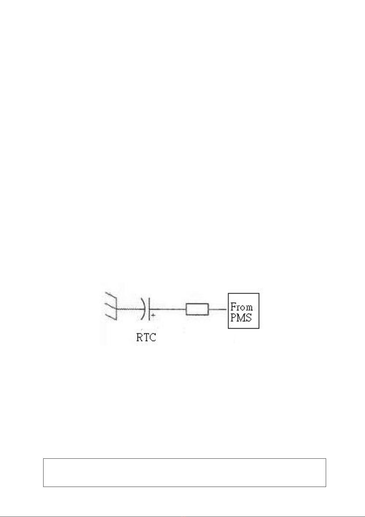
3RTC (RTC Battery) ............................................................................................................5
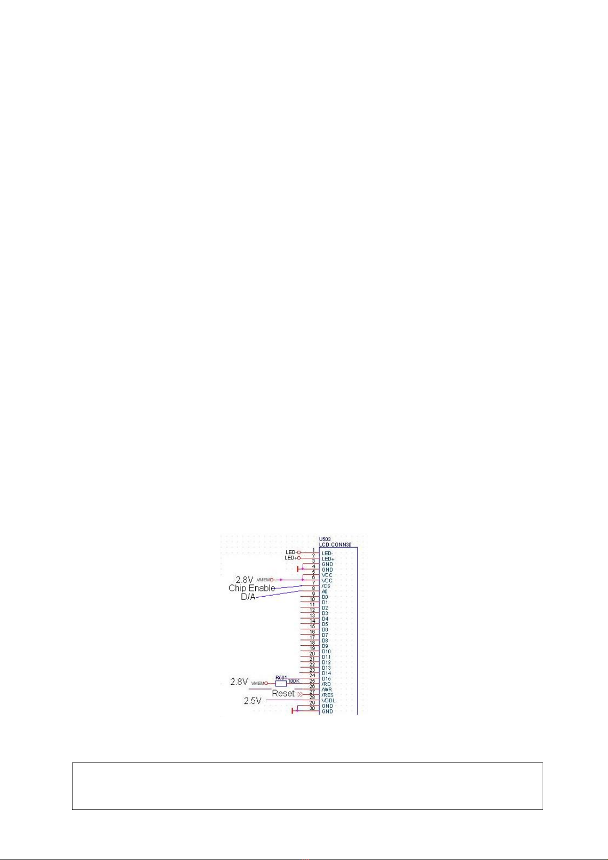
4LCD Connector (J503).......................................................................................................8
5Camera Connector (J504)...............................................................................................11
6Speaker Spring (JP202) ..................................................................................................14
7SIM Connector (J101)......................................................................................................17
8MIC Connector (JP201)...................................................................................................20
9Battery Connector (JP301)..............................................................................................23
10 IO Connector (JP401)...................................................................................................26
11 Earpiece (JP203)..........................................................................................................29
12 Joystick (SW401)..........................................................................................................32
13 Keypad Connector (JP402)..........................................................................................35
14 FUSE (F401) ................................................................................................................38

s Com
V 1.1 Page 3of 39 COM MD CC GRM T
ST55 Company Confidential
Copyright 2003© Siemens AG 01/05
1 Introduction
ST55 product family, consists of 1 tripleband (GSM900, GSM1800 and GSM1900) handset
Partnumber on IMEI label:
ST55: S36880-S6850-T100
This manual is intended to help you carry out repairs on level 2.5, meaning limited
component repairs. The documented failure highlights should be repaired in the local
workshops.
All repairs have to be carried out in an environment set up according to the ESD
(Electrostatic Discharge Sensitive Devices) regulations defined in international standards.
If you have any questions regarding the repair procedures or technical questions about the
spare parts do not hesitate to contact our technical support team in Kamp-Lintfort, Germany:
Tel.: +49 2842 95 4666
Fax: +49 2842 95 4302
E-mail: [email protected]

s Com
2 Repair Location Code
The front side of M/B (Connect with keys)
7. JP301
8. JP401 2. J503
4. JP202
3. J504
6. JP201 5. J101 1. RTC
The rear side of M/B
10. SW401
11. JP402
9. JP203
2.1 Code Description
1 RTC RTC 7 JP301 BATT Connector
2 J503 LCD Connector 8 JP401 IO Connector
3 J504 Camera Connector 9 JP203 Receiver
4 JP202 Speaker Spring 10 SW401 Joystick
5 J101 SIM Connector 11 JP402 Keypad Connector
6 JP201 MIC Connector
V 1.1 Page 4of 39 COM MD CC GRM T
ST55 Company Confidential
Copyright 2003© Siemens AG 01/05

s Com
3 RTC (RTC Battery)
3.1 Affected Units
Type: ST55
Affected IMEIs / Date Codes: All/All
Affected SW-Versions: All
3.2 Fault Description
Fault Symptoms for customers:
Time/Clock will reset each time power on.
No call records can be saved.
Fault Symptom on GSM-Tester:
None
Component Information
The RTC is a capacitor that supplies the power to the system to make the real time clock go on
counting about 45minutes after the main battery of phone is taken off. Besides, the RTC battery
will always be charged from the PMS when the main battery is inside the phone. See drawing
below.
PMS: Power Management System
V 1.1 Page 5of 39 COM MD CC GRM T
ST55 Company Confidential
Copyright 2003© Siemens AG 01/05

s Com
V 1.1 Page 6of 39 COM MD CC GRM T
ST55 Company Confidential
Copyright 2003© Siemens AG 01/05
3.3 Repair Document
Description of procedure
Diagnosis
Visual check and measure with a multimeter to detect if the RTC is oxidized or
deformed.
Repair by component change
1. Remove the defected RTC by Hot Air Blower (350°C ~ 400 °C) (350~400 °C).
2. Put on new RTC and add solder at the “+” side first.
3. Then add solder at the “-“ side.
Repair by SW-Booting
Not possible!
Test
Retest handset after repair procedure as described above
List of needed material
Components
ST55 RTC battery
Part Number: L36385-F505-X
Jigs and Tools
Hot Air Blower (350°C ~ 400 °C)
Soldering Iron (350°C ± 20 °C)
Special Tools:
Multimeter
Working materials
Desolder Wick / Braid
Solder

s Com
Drawings
Figure 1.1: ST55 Board RTC Side (Top View)
¨―
Figure 1.2: ST55 Board RTC Placement (RTC) (Top View)
V 1.1 Page 7of 39 COM MD CC GRM T
ST55 Company Confidential
Copyright 2003© Siemens AG 01/05

s Com
4 LCD Connector (J503)
4.1 Affected Units
Type: ST55
Affected IMEIs / Date Codes: All/All
Affected SW-Versions: All
4.2 Fault Description
Fault Symptoms for customers:
No screen or wrong display.
Fault Symptom on GSM-Tester:
None
Component Information
The LCD Cable Connector is a 30-pins contact type socket. There are 2 type signals transmitted
through this connector.
1. LCD signal:
A2, D0~D15, WR, REST, VDD 2.8V,VDDL 2.5V are used to transmitted the address signal, data
signal, control signal and power signal of LCD.
2. Backlight LED signal:
There is 11V power supplied to the anode of backlight LED via D303. LCDlight - connects the
cathode of backlight LED and the resister that can limit the current passing through the LED.
V 1.1 Page 8of 39 COM MD CC GRM T
ST55 Company Confidential
Copyright 2003© Siemens AG 01/05

s Com
V 1.1 Page 9of 39 COM MD CC GRM T
ST55 Company Confidential
Copyright 2003© Siemens AG 01/05
4.3 Repair Document
Description of procedure
Diagnosis
Visual check and measure with a multimeter to detect if pins are cold, insufficient
soldering, oxidized or deformed.
Repair by component change
1.Re-solder this connector if cold or insufficient soldering.
2.Use hot blower to remove defective connector and add solder on pads.
Avoid excessive heat! Watch surrounding component!
3.Heat and put on a new connector to enhance adhesion.
4.Re-solder new connector afterwards.
Repair by SW-Booting
Not possible!
Test
After repair procedure as described above, power on handset and check the display.
List of needed material
Components
ST55 LCD Connector
Part Number: L36334-Z97-C311
Jigs and Tools
Hot Air Blower (350°C ~ 400 °C)
Soldering Iron (350°C ± 20 °C)
Special Tools:
Multimeter
Working materials
Solder; Desolder Wick / Braid

s Com
Drawings
Figure 2.1: ST55 Board LCD Connector Side (Top View)
Figure 2.2: ST55 Board LCD Connector Placement (J503) (Top View)
V 1.1 Page 10of 39 COM MD CC GRM T
ST55 Company Confidential
Copyright 2003© Siemens AG 01/05

s Com
5 Camera Connector (J504)
5.1 Affected Units
Type: ST55
Affected IMEIs / Date Codes: All/All
Affected SW-Versions: All
5.2 Fault Description
Fault Symptoms for customers:
The picture captured by camera can’t be shown on screen or abnormal display.
Fault Symptom on GSM-Tester:
None
Component Information
The camera connector is a 26-pins contact type socket. It had 2 kinds of working voltage (2.8 and
2.5V), 13MHz-working frequency. Using the YUV data format.
V 1.1 Page 11of 39 COM MD CC GRM T
ST55 Company Confidential
Copyright 2003© Siemens AG 01/05

s Com
V 1.1 Page 12of 39 COM MD CC GRM T
ST55 Company Confidential
Copyright 2003© Siemens AG 01/05
5.3 Repair Document
Description of procedure
Diagnosis
Visual check and measure with a multimeter to detect if the pins are cold, insufficient
soldering, oxidized or deformed.
Repair by component change
1.Re-solder this connector if cold or insufficient soldering.
2.Use hot blower to remove defective connector and add solder on pads.
Avoid excessive heat! Watch surrounding component!
3.Heat and put on a new connector to enhance adhesion.
4.Re-solder new connector afterwards.
Repair by SW-Booting
Not possible!
Test
After repair procedure as described above, power on handset and check the camera
function.
List of needed material
Components
ST55 Camera Connector
Part Number: L36334-Z97-C323
Jigs and Tools
Hot Air Blower (350°C ~ 400 °C) (350~400 °C)
Soldering Iron (350°C ± 20 °C)
Special Tools:
Multimeter
Working materials
Solder

s Com
Drawings
Figure 3.1: ST55 Board Camera Connector Side (Top View)
Figure 3.2: ST55 Board Camera Connector Placement (J504) (Top View)
V 1.1 Page 13of 39 COM MD CC GRM T
ST55 Company Confidential
Copyright 2003© Siemens AG 01/05

s Com
6 Speaker Spring (JP202)
6.1 Affected Units
Type: ST55
Affected IMEIs / Date Codes: All/All
Affected SW-Versions: All
6.2 Fault Description
Fault Symptoms for customers:
No ring tone while setting and a call coming.
Fault Symptom on GSM-Tester:
None
Component Information
The speaker spring connector is used to contact a 8ohm speaker. It provides two contact trace
for the melody signal from the Melody IC. See drawing below.
V 1.1 Page 14of 39 COM MD CC GRM T
ST55 Company Confidential
Copyright 2003© Siemens AG 01/05

s Com
V 1.1 Page 15of 39 COM MD CC GRM T
ST55 Company Confidential
Copyright 2003© Siemens AG 01/05
6.3 Repair Document
Description of procedure
Diagnosis
Visual check if the springs are oxidized or deformed.
Repair by component change
1.Use hot blower to remove the defective connector.
Avoid excessive heat! Watch surrounding components!
2.Add solder on pads.
3.Heat and put on a new connector to enhance adhesion.
Repair by SW-Booting
Not possible!
Test
After repair procedure as described above, retest handset by ‘*#369#’.
List of needed material
Components
ST55 Speaker Spring
Part Number: L36334-Z97-C324
Jigs and Tools
Soldering Iron (350°C ± 20 °C)
Special Tools:
Multimeter
Working materials
Solder

s Com
Drawings
Figure 4.1: ST55 Board Speaker Spring Side (Top View)
Figure 4.2: ST55 Board Speaker Spring Placement (JP202) (Top View)
V 1.1 Page 16of 39 COM MD CC GRM T
ST55 Company Confidential
Copyright 2003© Siemens AG 01/05

s Com
7 SIM Connector (J101)
7.1 Affected Units
Type: ST55
Affected IMEIs / Date Codes: All/All
Affected SW-Versions: All
7.2 Fault Description
Fault Symptoms for customers:
Always “Insert SIM card” showed under normal operation.
Fault Symptom on GSM-Tester:
No response!
Component Information
The SIM connector is a mechanical part designed to make a connection with SIM Card (GSM
11.11). The power will be supplied into VCC and VPP. The signal of RESET, CLOCK and DATA
from DBP transmit to RST, CLK, and I/O.
V 1.1 Page 17of 39 COM MD CC GRM T
ST55 Company Confidential
Copyright 2003© Siemens AG 01/05

s Com
V 1.1 Page 18of 39 COM MD CC GRM T
ST55 Company Confidential
Copyright 2003© Siemens AG 01/05
7.3 Repair Document
Description of procedure
Diagnosis
Visual check and measure with multimeter if pins are cold, insufficient soldering,
oxidized or deformed.
Repair by component change
1.Re-solder this connector if cold or insufficient soldering.
2.Use hot blower to remove the defective connector if oxidized or deformed and absorb
remaining tin on pads.
3.Put on new connector and add solder on pins in diagonal sequence.
Repair by SW-Booting
Not possible!
Test
After repair procedure as described above, insert SIM card.
List of needed material
Components
ST55 SIM Connector
Part Number: L36334-Z97-C325
Jigs and Tools
Hot Air Blower (350°C ~ 400 °C)
Soldering Iron (350°C ± 20 °C)
Special Tools:
Multimeter
Working materials
Desolder Wick / Braid
Solder

s Com
Drawings
Figure 5.1: ST55 Board SIM Connector Side (Top View)
Figure 5.2: ST55 Board SIM Connector Placement (J101) (Top View)
V 1.1 Page 19of 39 COM MD CC GRM T
ST55 Company Confidential
Copyright 2003© Siemens AG 01/05

s Com
8 MIC Connector (JP201)
8.1 Affected Units
Type: ST55
Affected IMEIs / Date Codes: All/All
Affected SW-Versions: All
8.2 Fault Description
Fault Symptoms for customers:
The called party can’t hear any voice.
Fault Symptom on GSM-Tester:
None
Component Information
The MIC connector is a two pins holder. See drawing below. There will be about 1.2V bias on
PIN-2 as the system is power on. The voice trace here is single end structure. Voice signal will
be received by the microphone and goes to the VBC via PIN-2.
V 1.1 Page 20of 39 COM MD CC GRM T
ST55 Company Confidential
Copyright 2003© Siemens AG 01/05
Other manuals for ST55
2
Table of contents
Other Siemens Cell Phone manuals

Siemens
Siemens S66 User manual

Siemens
Siemens M46 User manual

Siemens
Siemens Emoty User manual

Siemens
Siemens Controller User manual

Siemens
Siemens S6 User manual

Siemens
Siemens PEGASUS-DTC AX72 User manual

Siemens
Siemens CF75 Setup guide

Siemens
Siemens XELIBRI 2 User manual

Siemens
Siemens C61 User manual

Siemens
Siemens Gigaset SL55 User manual

Siemens
Siemens SL42 User manual

Siemens
Siemens AX76 User manual

Siemens
Siemens S65 Setup guide

Siemens
Siemens S40 User manual

Siemens
Siemens AP75 User manual

Siemens
Siemens SL45 User manual

Siemens
Siemens C25 User manual

Siemens
Siemens C62 User manual

Siemens
Siemens MC60 User manual

Siemens
Siemens Gigaset SL75 WLAN User manual