Company Confidential
Copyright 2004© Siemens AG
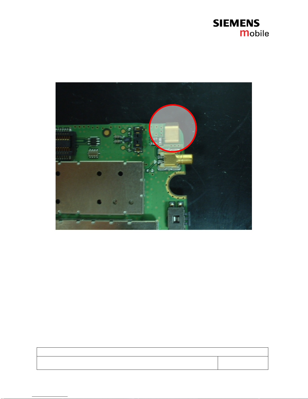
3
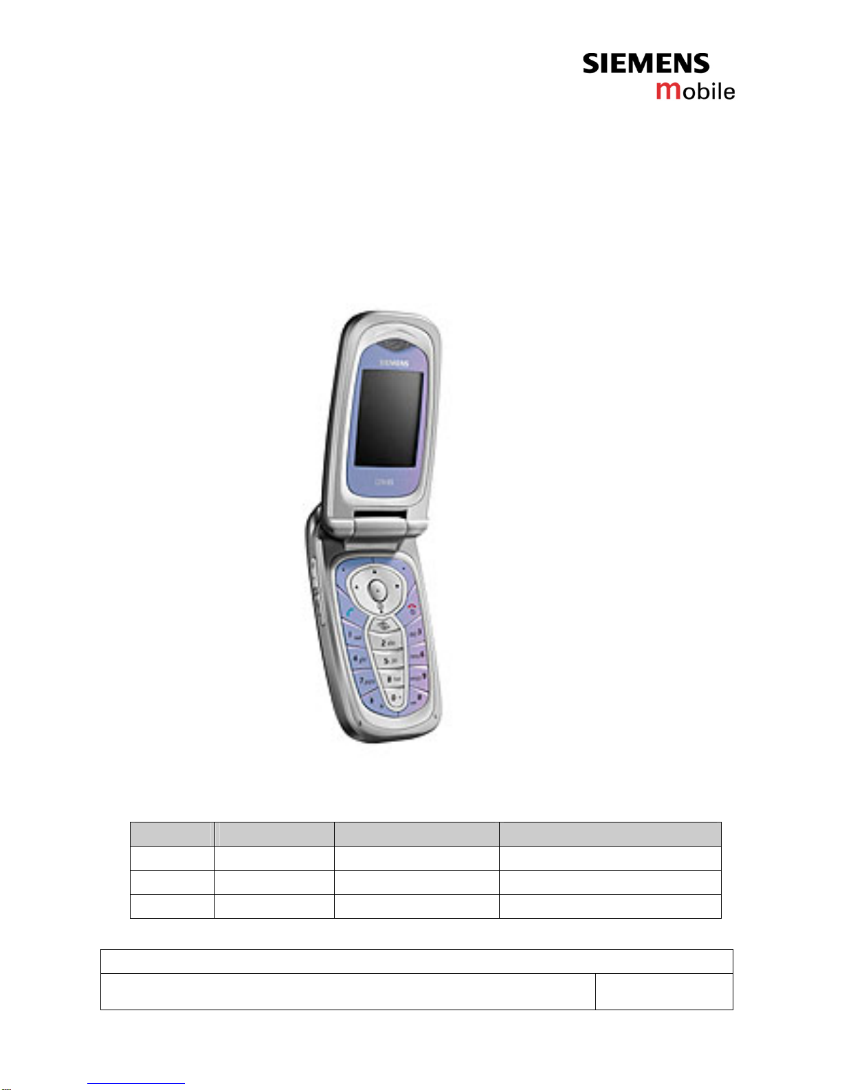
Service Repair Documentation
Level 2.5 - CFX65 V1.0
Table of content
CFX 65 BOARD LAYOUT ...................................................................................................................... 4
LCM LAYOUT......................................................................................................................................... 6
1. B TO B CONNECTOR (J305) .......................................................................................................... 7
2. RF SWITCH (ANT300) ..................................................................................................................... 8
3. ANTENNA SPRING (J301) .............................................................................................................. 9
4. SPEAKER CONNECTOR (J200)................................................................................................... 11
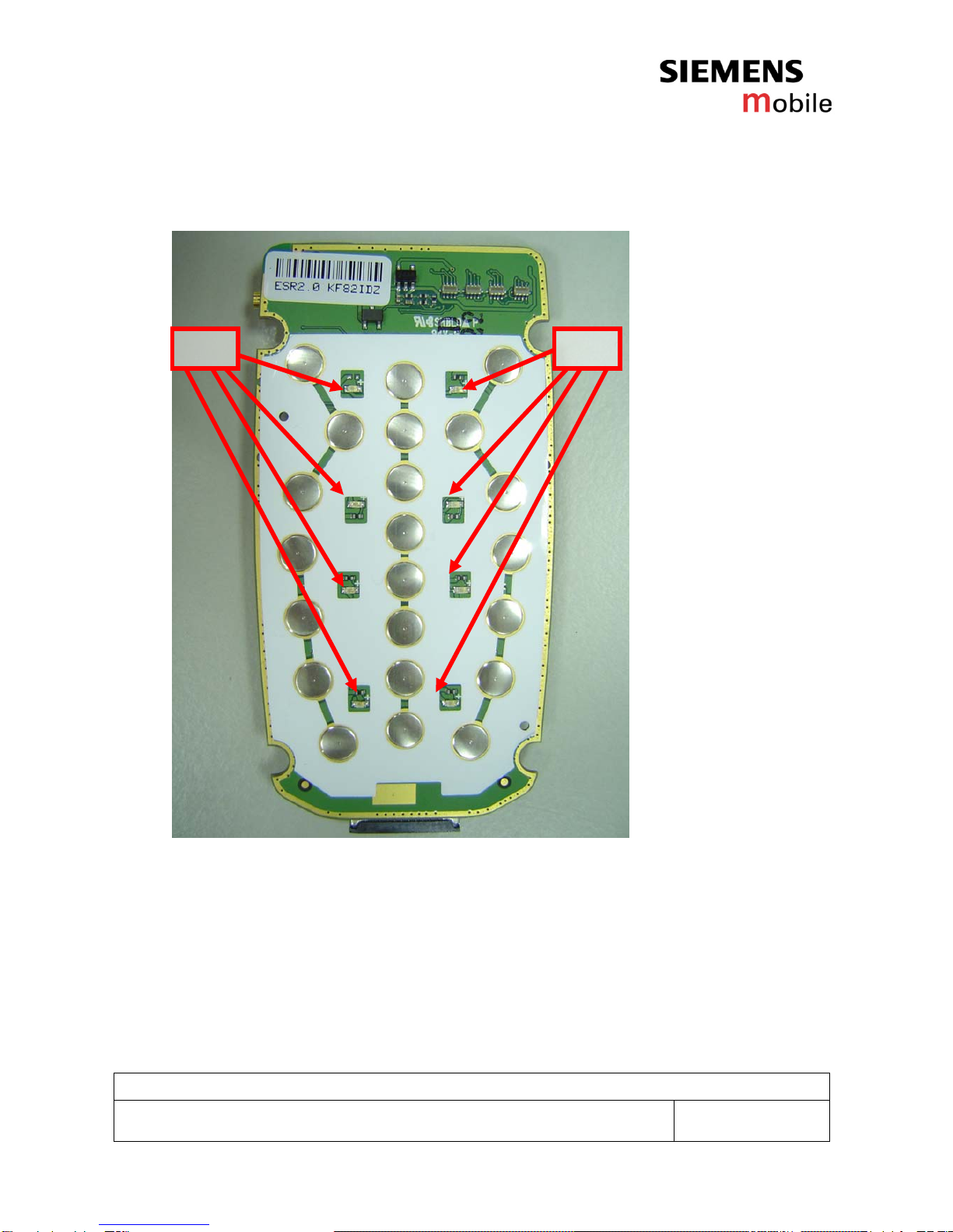
5. SIDE KEY SWITCH (S400,S401)................................................................................................... 13
6. SIM READER (J302)...................................................................................................................... 15
7. I/O CONNECTOR (J304)................................................................................................................ 17
8. BACKUP BATTERY (BT414R)...................................................................................................... 18
9. IRDA (U103) ................................................................................................................................... 20
10. BATTERY CONNECTOR (J300).................................................................................................... 22
11. FUSE (F300).................................................................................................................................... 24
12. LED ON PCBA................................................................................................................................26
13. CAMERA CONNECTOR................................................................................................................. 28
14. CAMERA MODULE ........................................................................................................................ 30
15. FLASH LED..................................................................................................................................... 32