Installation Instructions
11-B-1059-01 Rev. 00
-3-
-2-
DANGER
Hazardous voltage.
Will cause death or
serious injury.
Keep out.
Qualified personnel only.
Disconnect and lock off all
power before working on
this equipment.
15. Torque all connections to the values specified in
these instructions or on
the Hardware Tightening
Torque label affixed to the rear of the deadfront.
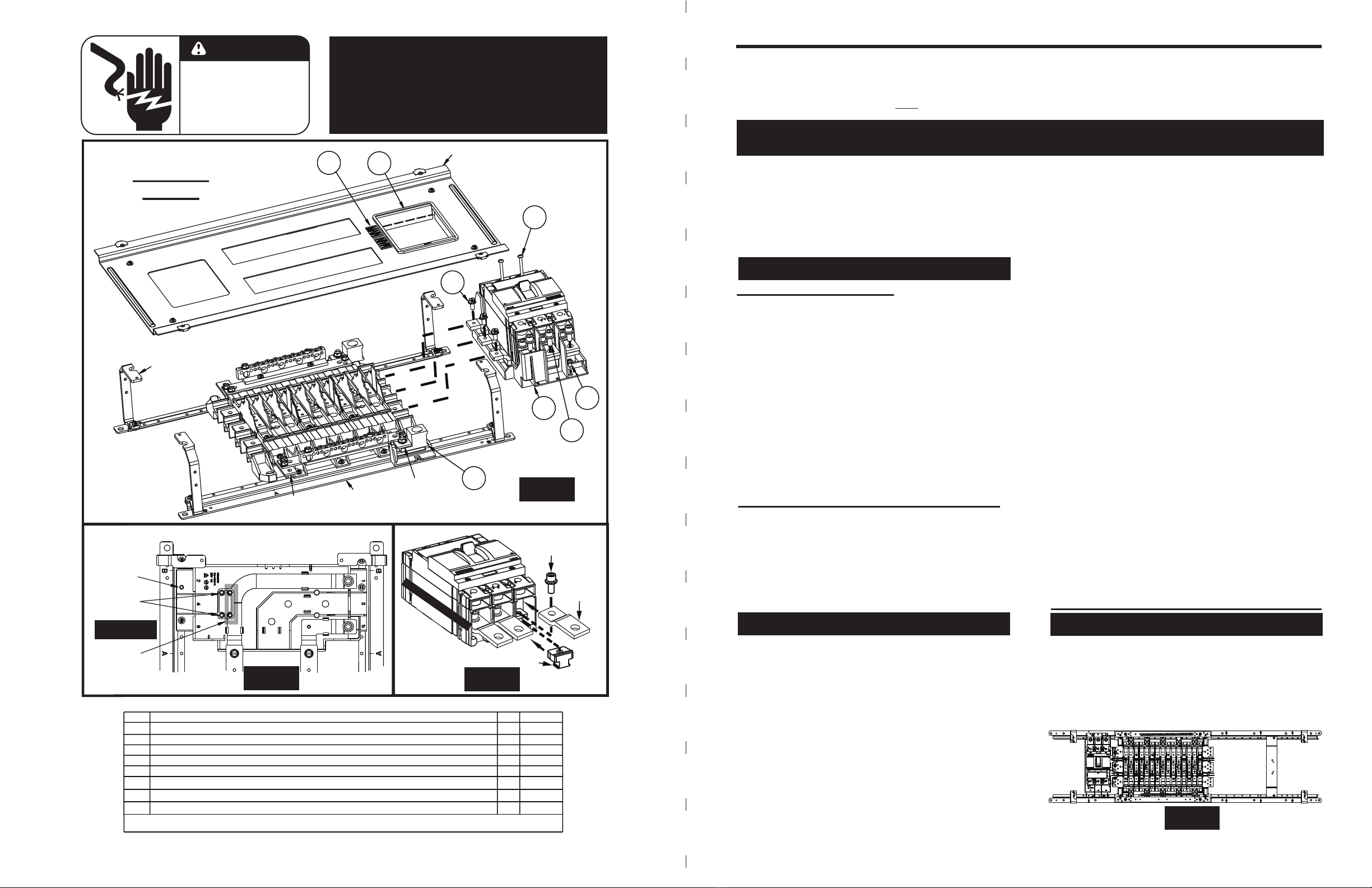
8. Position the Strap and Barrier Assembly (Item 1) at
the MAIN END of the panel. (See Fig. 1)
Ensure the straps are
properly snapped into the
barrier and then align them
below the panel bus.
14. For 1-phase 3-wire and 3-phase 4-wire systems,
the Neutral Lug Assembly (Item 6) is required.
The Neutral Lug Assembly arrives in the kit ready
to assemble at any open corner. Install by
positioning it below the neutral cross bus or the
neutral lug pad, inserting the exposed stud
through the appropriate hole and
securing with the
1/4”-20 belleville washer nut (part of Item 6).
The following instructions are for the installation of a Siemens main or subfeed breaker kit for Type 3VA52 (MFAS, HFAS
or CFAS), Type 3VA61 (MDAE, HDAE or CDAE) or Type 3VA62 (MFAE, HFAE or CFAE) breakers in Revised P1
Panelboards. The kit may be installed as a main or a subfeed in panels rated 250 amps or less. For Revised P1 400A
panels, it may be installed in subfeed applications ONLY (see Fig. 2). The parts provided enable connection to a 1-phase,
2 or 3-wire system with the use of kit MBKVA5262A or for connection to a 3-phase, 3 or 4-wire system with the use of kit
MBKVA5262B. The breaker is NOT included with this kit and must be purchased separately. Be sure to choose the
appropriate breaker for the system in use. For systems without neutrals, disregard the neutral connection instructions.
9. Loosely fasten the Strap and Barrier Assembly to
the Base Rails with
two #10-24 screws (Item 4)
and
the straps to the phase bus with 1/4”-20 SEMS
screws (Item 2). Do not tighten at this time.
13. Torque all connections to the values specified in
these instructions or on the Hardware Tightening
Torque label affixed to the rear of the deadfront.
16.
Attach the main cables to the breaker and neutral
terminal and torque connections
to values specified
on the device. If no values are listed on the device,
refer to the device manual or the Hardware
Tightening Torque label affixed to the rear of the
deadfront.
17. Remove the blank filler or escutcheon installed on
any deadfront opening in the area that will cover
this kit. Install the Escutcheon (Item 7) provided
with this kit into the front of the deadfront as shown.
For detailed filler plate installation instructions,
refer to instruction sheet 11-B-1061-01 (included
in this kit).
18. For main breaker applications, apply the “MAIN”
labels (Item 8) on the front of the deadfront, near
the breaker escutcheon, as shown.
19. Before energizing the panel, ensure that all
connections have been properly torqued, the
deadfront is installed and all fillers are in place.
20. Follow Steps 1 through 17, except that the kit
must be installed at the feed-thru or subfeed end
of the panel and any pre-existing assembly at that
location must be removed prior to installation of
this kit. In addition, do NOT install the “MAIN”
labels (skip Step 18). Finish with Step 19.
For installation as a main breaker:
For installation as a subfeed breaker:
1. Lock off all power supplying this equipment
before working on it.
3. Remove the Main / Subfeed lugs (if installed).
2. Remove the deadfront.
(For 250A panels ONLY)
MAIN
END
FEED-
THRU
OR
SUBFEED
END
P1-400 PANELBOARD WITH SUBFEED BREAKER
Fig. 4
5. Locate the Breaker Hardware Kit (Item 5) and the
breaker (SOLD SEPARATELY).
Prepare the breaker:
6. Select the proper nut keepers and slide them
under each phase of the breaker stabs on the
“ON”-side of the breaker. They “click” into place
when properly inserted. (See Fig. 3)
NOTE: Hardware Kit includes two sets of Nut
Keepers; one set for 3VA52 breakers and one set
for 3VA61 / 3VA62 breakers.
10. Orient the breaker such that the “ON”-side (with
Bus Extensions) fits onto the barrier carefully
aligned with the two fins and bus straps. The
“OFF”-side breaker mount holes are aligned with
the inner inserts for 3VA52 breakers and outer
inserts for 3VA61/3VA62 breakers. Breaker
terminals 1, 3 & 5 and 2, 4 & 6 should align with
the numeric markings on the barrier (See Fig. 2)
12. Loosely fasten the breaker “OFF”-side to the
Strap and Barrier Assembly using two #8-32 x 3”
Breaker Mounting Screws (part of Item 5) and
torque to 13.3 ± 1.8 lb-in.
NOTE: Do not use any breaker mounting screws
shipped with the breaker in this assembly.
7. Place a bus extension (part of Item 5) on top of
each phase of the breaker stabs, with the smaller
hole towards the breaker and with the anti-turn
protrusions down. Loosely secure each phase with
socket-head screws. Do not tighten at this time.
3-PHASE
P1-250
MAIN
END
FEED-THRU
OR
SUBFEED
END
1
5
2
DEADFRONT
SUPPORT
BASE
RAIL
NEUTRAL
LUG PAD
NEUTRAL
CROSS BUS
6
7
Fig. 1
4
3
8
DEADFRONT
4. Review the details at the bottom of page 1 and
the top of page 4. If these other parts are
needed, order and install them prior to continuing.
Refer to the Hardware Kit BBKVA5262P2HW (Item 5) instruction sheet
(11-B-1050-01) for more detail, but use the torques on this instruction.
SOCKET-HEAD
SCREW
BUS
EXTENSION
NUT KEEPER
“ON”
SIDE OF
BREAKER
(Breaker NOT included)
“OFF” SIDE OF
BREAKER
Fig. 3
11. Loosely fasten the breaker “ON”-side to the Strap
and Barrier Assembly using one 5/16”-18 screw
(Item 3) for each strap.
STRAP AND BARRIER ASSEMBLY 1
1/4”-20 x 1/2” HEX HEAD SEMS* ASSEMBLY SCREW
#10-24 x 7/16” SLOTTED HEX WASHER THREAD-FORMING SCREW
** (2) for 1Ø, (3) for 3Ø
**
2
1
2
3
4
5/16”-18 x 3/4” SOCKET HEAD CAP MACHINE SCREW
**
5
6
* SEMS assembly screws have a captive washer on the screw
THIS KIT CONTAINS THE FOLLOWING ITEMS:
ITEM QTY
DESCRIPTION
N/A
30 lb-in
TORQUE
72 lb-in
177 lb-in
1
3VA52 / 3VA62 HARDWARE KIT FOR P2 / P3, 1-PH / 3-PH N/A
1
NEUTRAL LUG ASSEMBLY N/A
MAIN LABEL
2
8N/A
BREAKER ESCUTCHEON
1
7N/A
KEY:
(Kit No. BBKVA5262PHW)
TO SECURE
SERVICE
ENTRANCE
BARRIER
3VA61/62
BREAKER
MOUNT
HOLES
3VA52
BREAKER
MOUNT
HOLES
TORQUE TO
13.3±1.8 lb-in
Fig. 2
BARRIER DETAIL
(SINGLE-PHASE SHOWN)
NOTE: Kits that include a breaker will have
the following items pre-assembled to the
breaker and are not included as separate parts:
(1) Type 3VA circuit breaker
(2) #8-32 socket-head thread-forming screws
(1) strap and barrier assembly
(1) 3VA52/3VA62 hardware kit
NOTE: Some main breaker kits may include this kit AND a breaker with the strap and barrier assembly
attached. White text on black background on these pages denote instructions specific to these particular
kits (see list on front cover). (For clarification, DANGER warning below applies to all.)
For pre-installed breaker kits (list on page 1),
skip the “Prepare the breaker” instructions
For pre-installed breaker kits (list on page 1),
skip Steps 10, 11 and 12 For pre-installed breaker kits (list on page 1),
follow Steps 1-4, 8-9, 13-17 and 19.


