Installation
Introduction
Type
RL
Low
Voltage
AC
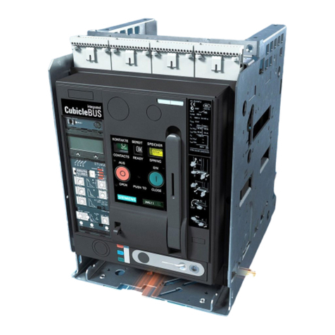
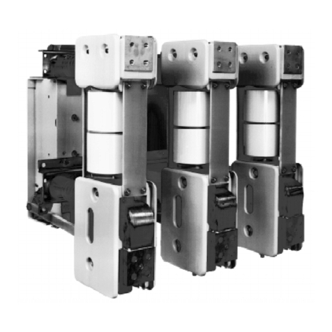
Power Circuit Breakers may be fur-
nished for mounting in any one
of
three ways:
1.
In
switchboards or
in
metal enclosed switchgear
of
the
drawout type;
2.
In
individual metal enclosures (drawout type);
3. For stationary mounting
in
the user's own enclosure or
switchboard.
All
RL
circuit breakers are completely assembled, tested, and
calibrated at the factory
in
a vertical position and
..
must
be so
installed
to
operate properly.
The.
user's.primary connections
must
be adequately braced against the effects of
short
cir-
cuit currents
to
prevent overstressing the circuit breaker ter-
minals.
Receiving and Inspection for Damage
IMPORTANT: Do not accept the statement from any
driver
that
the
damaged equipment was not properly
packaged by shipper.
Do not sign Bill
of
Lading
without
notation of visible
damage if observed. Our equipment packaging meets
the
rigid
requirements
established
by
the
trucking
industry.
You
must
obtain carrier inspectioll within 15 days of
receipt
on
damaged equipment.
Immediately upon receipt
of
this equipment, carefully remove
all
packing braces. Examine parts
and
check them against the
packing list
and
note any damage incurred
in
transit
If
damage
is disclosed, a carrier inspection
must
be arranged for by
consignee within 15 days of receipt of equipment. If equipment
is shipped F.O.B. Destination, the consignee must obtain the
original
of
the carrier inspection report and notify Siemens
immediately.
Two shipping methodS are used with
RL
circuit breakers:
1.
Individually skidded with protective covering.
2.
Within a cubicle.
Note
all
caution tags, remove any blocking,
and
open circuit
breaker contacts before installation.
Storage
Whenever possible, install circuit breakers
in
their assigned
switchgear compartments
for
storage. Follow instructions
contained
in
the instruction manual for types R
and
SR
Low
Voltage Metal-Enclosed Switchgear,
SG-3088.
When the circuit
breaker
is
stored separately, place the circuit breaker
on
a sturdy
pallet. Secure the circuit breaker
to
the pallet.
and
cover
with
polyethylene film at least 1Omils thick. Also obseNe the following:
1.
Indoor Storage -Whenever possible, store
the
circuit
breaker indoors. The storage environment must be clean,
dry and free
of
such conditions
as
construction dust, corro-
sive atmosphere, mechanical abuse
and
rapid temperature
variations.
2.
Outdoor Storage -OUTDOOR
STORAGE
IS
NOT
REC-
OMMENDED. When no other option is available, the cir-
cuit breaker
must
be completely covered and protected
from
rain,
snow, dirt
and
all
other contaminants.
3. Space Heating -Space heating
must
be used for both
indoor and outdoor storage
to
prevent condensation and
corrosion. Space heaters
of
approximately 100 watts per
breaker are recommended. ·tf
the
circuit
breakers are
stored inside their assigned switchgear compartments,
and the switchgear is equipped
with
space heaters, the
switchgear space heaters should be energized.
General
The
·RL
Low
Voltage
AC
Power Circuit Breaker is completely
adjusted, tested and inspected before shipment. However, a
careful check should be made
to
be certain that shipment or
storage has not resulted
in
damage or change of adjustment.
Circuit breakers
and
their enclosures should be installed in a
clean, dry, well-ventilated
area
in
which the atmosphere
is
free
from destructive acid or alkali fumes. For stationary breakers
and custom enclosures, the factory should be consulted for
minimum clearances and required ventilation openings.
Before installing, make certain that the circuit breaker contacts
are
in
the
open
position
and
that the closing springs
are
discharged.
Be
sure
to
lubricate primary
and
secondary disconnect fingers
with Siemens electrical contact lubricant, part
no.
15-171-370-002.
.A
DANGER
Hazardous voltages
and
high-speed moving
parts.
Will
cause death, serious personal injury
or
property damage.
To avoid electrical shock, burns and entanglement
in
moving parts, this equipment
must
be installed,
operated and maintained only by qualified persons
thoroughly familiar
with
the equipment, instruction
manuals
and
drawings.
A
WARNING
Heavy weight overhead.
Can cause
death,
serious personal injury
or
property damage.
Always use approved lifting means
to
handle cir-
cuit breakers or fuse carriages. Follow instructions
for
use
of
lifting bar assembly. Avoid excessive
speeds and sudden stops. Never
lift
a circuit break-
er
or
fuse carriage above
an
area
where personnel
are located.
3
Courtesy of NationalSwitchgear.com
