manuals.online logo
Brands
  1. Home
  2. •
  3. Brands
  4. •
  5. Siemens
  6. •
  7. Control Panel
  8. •
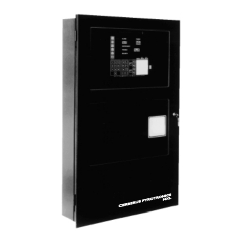
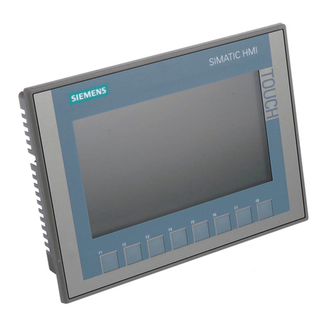
  9. Siemens CERBERUS PYROTRONICS PXL User manual

Siemens CERBERUS PYROTRONICS PXL User manual

Fire Safety
P/N 315-094131-5
Siemens Building Technologies, Inc.
8 Fe nwood Road
Flo ham Pa k, New Je sey 07932
Siemens Building Technologies, Ltd.
2 Kenview Bouleva d
B ampton, Onta io L6T 5E4 CN
(For PXL Firmware Revision 4.0 and higher)
Installation, Operation, and Maintenance Manual
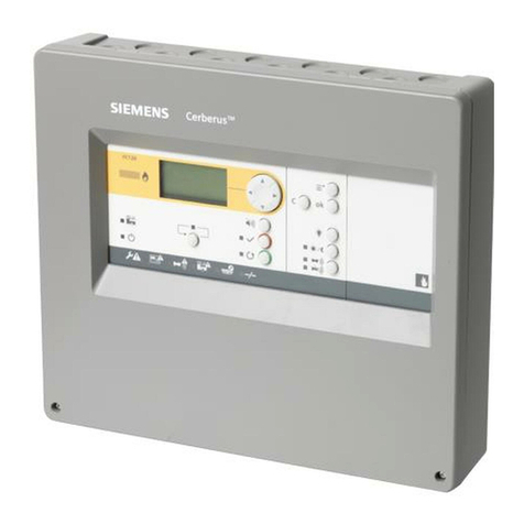
CERBERUS PYROTRONICS
PXL CONVENTIONAL FIRE ALARM CONTROL PANEL
Technical Manuals Online! - http://www.tech-man.com
firealarmresources.com
WARNING
ALL WIRING MUST BE DONE AS DESCRIBED BELOW
TO OBTAIN SAFE AND PROPER SYSTEM OPERATION.
1. Earth ground the PXL enclosure
properly; see the latest edition of the
National Electrical Code for approved
methods. Conduit ground is not
recommended as the primary
means of grounding.
2. Separate all wiring for initiating device
circuits (i.e., detectors, manual
stations, etc.) from all other wiring in
the PXL enclosure. To wire the
System in compliance with UL 864,
refer to the Power Limited Wiring
Instructions for the PSE-1 Enclosure,
P/N 315-094154.
3. INSULATE ALL CABLE DRAIN
WIRES from any conduit or earth
grounded electrical box, including
those in the PXL enclosure.
4. Connect shield cable drain wire
ONLY inside the PXL enclosure.
CAUTIONS AND WARNINGS
This caution symbol appears periodically throughout this manual. It
identifies important safety instructions. Read these instructions care-
fully. Failure to follow these instructions may result in damage to the
equipment.
This warning symbol appears periodically throughout this manual. It
identifies important safety instructions. Read these instructions care-
fully. Failure to follow these instructions may result in serious or fatal
personal injury or costly property damage.
Technical Manuals Online! - http://www.tech-man.com
firealarmresources.com
ContentsPXL Conventional FireAlarm Control Panel
i
Contents
1 The PXL Control Panel..................................................................... 1
INTRODUCTION ..................................................................................................1
Components of the Basic PXL System ..................................................................... 1
Components of the Expanded PXL System ............................................................. 3
2 Installing the PXL Control Panel ..................................................... 5
INTRODUCTION ..................................................................................................5
GENERAL GUIDELINES FOR PXL INSTALLATION...........................................5
STEP 1Install the PSE-1 ..........................................................................................
STEP 2Pull Field Wiring .......................................................................................... 9
STEP 3Install the PPS-10M ..................................................................................... 9
STEP 4Install the Optional PRM-4 ....................................................................... 12
STEP 5Install the Optional PNC-2Z ...................................................................... 14
STEP 6Install Interconnecting Cables ................................................................. 16
STEP Install the PCM-1 ....................................................................................... 1
STEP 8Install Interconnecting Cable ................................................................... 19
STEP 9Install the Optional PZE-4B ...................................................................... 19
STEP 10Install the PMK-1 Bracket in the PSE-1 ................................................. 22
STEP 11Install the PTX-12 .................................................................................... 23
STEP 12Install Grounding Straps ........................................................................ 24
STEP 13Check Field Wiring .................................................................................. 26
STEP 14Install Field Wiring .................................................................................. 26
Wiring to the PSE-1 Enclosure ............................................................................... 26
Initiating Device Circuits .......................................................................................... 30
Notification ppliance Circuits ................................................................................. 31
Wiring to the PCM-1................................................................................................32
Wiring to the Optional PZE-4B Modules ................................................................. 32
Wiring to the PPS-10M ........................................................................................... 32
Wiring to the PNC-2Z .............................................................................................. 33
Wiring to the PRM-4................................................................................................34
STEP 15Install All System Labels ........................................................................ 34
STEP 16Install the Door to the Backbox ............................................................. 34
STEP 1 Power-up the PXL ................................................................................... 34
3 Operating the PXL Control Panel .................................................. 35
INTRODUCTION ................................................................................................35
OPERATION .......................................................................................................36
Alarm ..........................................................................................................................36
Supervisory ............................................................................................................... 36
Trouble ....................................................................................................................... 36
Normal ........................................................................................................................ 36
Program ..................................................................................................................... 3
Responding to a Fire Alarm ..................................................................................... 3
Responding to a Supervisory Condition ................................................................ 38
Responding to a Trouble Condition ........................................................................ 38
Technical Manuals Online! - http://www.tech-man.com
firealarmresources.com
PXL Conventional FireAlarm Control Panel Contents
ii
4 Programming the PXL Control Panel ...........................................39
INTRODUCTION ................................................................................................39
Firmware Revisions .................................................................................................. 39
SYSTEM STARTUP............................................................................................40
System Programming and Testing .......................................................................... 41
FEATURES .........................................................................................................41
Set AC Fail Signal Delay ........................................................................................... 43
Alarm Verifications ................................................................................................... 43
ASCAutomatic System Configuration .................................................................. 43
Control ....................................................................................................................... 43
Delete Modules .......................................................................................................... 43
Help ............................................................................................................................44
History ........................................................................................................................44
History Clear .............................................................................................................. 44
Map Zones to Relays and Map Zones to Bells ....................................................... 44
Menu ........................................................................................................................... 45
Program ..................................................................................................................... 45
Responding Modules ................................................................................................ 45
Set Alarm Verification Retard/Reset Timer ............................................................. 45
Set Bell Codes ........................................................................................................... 46
Set Country Code ...................................................................................................... 46
Set Custom Messages .............................................................................................. 4
Set Global Relays ...................................................................................................... 4
Set NAC Cutoff Timer ............................................................................................... 4
Set NAC Inhibit Timer ............................................................................................... 4
Set Passcodes ........................................................................................................... 4
Set System ID ............................................................................................................ 4
Test ............................................................................................................................. 4
Zone Types ................................................................................................................ 48
Alarm Verification ................................................................................................. 48
Generic Zone ......................................................................................................... 49
Reset Zone ............................................................................................................. 49
5 Testing and Troubleshooting ........................................................53
WALK TEST .......................................................................................................53
SYSTEM TEST ...................................................................................................54
Every Six Months ...................................................................................................... 54
Every Year .................................................................................................................. 54
FUSE REPLACEMENT IN THE PXL SYSTEM..................................................54
TROUBLESHOOTING .......................................................................................55
TROUBLE MESSAGES .....................................................................................56
ppendix ......................................................................................59
P og amming Wo ksheets ...............................................................................59
ppendix B ......................................................................................65
Module Powe Calculations .............................................................................65
Elect ical Requi ements fo Batte y Calculations..........................................66
Technical Manuals Online! - http://www.tech-man.com
firealarmresources.com
ContentsPXL Conventional FireAlarm Control Panel
iii
Illustrations
1. Basic PXL System............................................................................................. 2
2. The PSE-1 Enclosure ....................................................................................... 7
3. Removing the P K-1 Bracket from the PSE-1 ................................................. 8
4. PPS-10 odule Board ................................................................................. 10
5. Sliding the PPS-10 into the P K-1 Bracket ................................................. 11
6. ounting the PPS-10 on the P K-1 Bracket ............................................... 11
7. PR -4 odule Board...................................................................................... 12
8. ounting the PR -4 on the P K-1 Bracket ................................................... 13
9. PNC-2Z odule Board .................................................................................... 14
10. ounting the PNC-2Z on the P K-1 Bracket ................................................. 15
11. ounting the PC -1 on the P K-1 Bracket ................................................... 18
12. Labeling the Zones and Terminal Blocks on the PC -1 ................................. 18
13. PZE-4B odule Board .................................................................................... 20
14. ounting the PZE-4B ...................................................................................... 20
15. Labeling the Zones and Terminal Blocks on the PZE-4B ................................ 20
16. Installing the P K-1 Bracket in the PSE-1...................................................... 22
17. ounting the PTX-12 ...................................................................................... 23
18. Installing the Grounding Strap with Two Lugs ................................................. 24
19. Installing the Grounding Strap with One Lug .................................................. 25
20. PXL Power Limited Wiring .............................................................................. 28
21. The PC -1 User Interface ..............................................................................35
22. PXL Automatic System Configuration ode ................................................... 40
23. PXL Normal Operating ode .......................................................................... 42
24. Line Graph of Alarm Verification ..................................................................... 49
25. PPS-10 Wiring for Canadian Automatic Battery Disconnect ........................ 68
ppendix C ......................................................................................67
Configu ing and P og amming the PXL Fi e Ala m System fo
Use in Canada ...................................................................................................67
ppendix D ......................................................................................69
Silent Knight 5128/5129 Digital Fi e Communicato Connected
to the PXL Cont ol Panel Repo ting PXL Cont ol Panel Conditions
to a Cent al Station o PXL as a Remote Supe vising Station Fi e Ala m
System ...............................................................................................................69
ppendix E ...................................................................................... 73
Wi ing in an Expanded System (PSE-2 Enclosu e) .......................................73
Technical Manuals Online! - http://www.tech-man.com
firealarmresources.com
PXL Conventional FireAlarm Control Panel Contents
iv
Tables
1. Setting the Address on the PPS-10 ................................................................ 9
2. Setting the Address on the PR -4 .................................................................. 12
3. Setting the Address on the PNC-2Z ................................................................ 14
4. Setting the Address on the PZE-4B ................................................................ 19
5. Field Wiring Checkout Procedure ................................................................... 27
6. Non-power Limited Wiring............................................................................... 29
7. Power Limited Wiring ......................................................................................29
8. Wiring to the PC -1........................................................................................ 32
9. Wiring to the Optional PZE-4B ........................................................................ 32
10. Wiring to the PPS-10 ................................................................................... 32
11. Wiring to the Optional PNC-2Z ....................................................................... 33
12. Wiring to the Optional PR -4 ......................................................................... 34
13. PXL Programming Options.............................................................................. 51
14. PXL Fuse Replacement .................................................................................. 55
15. Silent Knight odel 5128/5129 Programming Table ....................................... 72
Illustrations (Cont.)
26. ounting the Silent Knight odel 5128 in a PXL Enclosure ........................... 70
27. PXL to Silent Knight odel 5128/5129 Wiring Diagram.................................. 71
28. Cabling Connections in a PSE-2 Enclosure with Full odule Capacity .......... 73
29. Cabling Connection in a PSE-2 Enclosure with Full Zone and Relay Capacity74
PXL Connection Diagram ....................................................................Last Page
Technical Manuals Online! - http://www.tech-man.com
firealarmresources.com
IntroductionPXL Conventional FireAlarm Control Panel
1
1 The PXL Control Panel
INTRODUCTION
The CERBERUS PYROTRONICSTM PXL Control Panel is a micro-
processor-based conventional fire protection system. The basic PXL
System has 12 Initiating evice Circuits (I Cs), 4 Notification Appli-
ance Circuits (NACs), and 3 dedicated Form C relays for Alarm,
Trouble, and Supervisory conditions.
Components of the Basic PXL System
The following components are included in the basic PXL Control
Panel:
 PCM-1 Main Control Board with
- 12 Initiating evice Circuits
- user controls
 PPS-10M Power Supply with
- 4 Notification Appliance Circuits
- 3 dedicated Form C relays
 PTX-12 Power Transformer
 PSE-1 Enclosure with
- PMK-1 Mounting Bracket
 Batteries, which must be purchased separately, that are capable
of supplying all power necessary to operate the PXL and supply
1 amp auxiliary +24 V C and up to 10 amps of NAC current at
24 volts when in alarm.
NOTE: Both the Auxiliary current and the NAC current together
cannot exceed 10 Amps.
Technical Manuals Online! - http://www.tech-man.com
firealarmresources.com
PXL Conventional FireAlarm Control Panel Introduction
2
CERBERUS PYROTRONICS
PXL SYSTEM NORMAL
<MENU
12:00:00
POWER
ALARM
SUPERVISORY
TROUBLE
AUDIBLES SILENCED
PARTIAL DISABLE
CERBERUS PYROTRONICS
Figure 1
Basic PXL System
Exterior View
Interior View
Technical Manuals Online! - http://www.tech-man.com
firealarmresources.com
IntroductionPXL Conventional FireAlarm Control Panel
3
Components of the Expanded PXL System
The addition of the following components to the Basic PXL System
can expand the PXL Control Panel to its maximum configuration of
36 Initiating evice Circuits, 16 Notification Appliance Circuits, 3
dedicated Form C relays, and 32 user-defined Form C relays:
 PZE-4B Zone Expander modules (up to a maximum of 6
modules)
 PNC-2Z Notification Appliance Circuit modules (up to a maxi-
mum of 4 modules)
 PRM-4 Relay modules (up to a maximum of 8 modules)
 PSE-2 Enclosure
 An additional PPS-10M Power Supply and PTX-12 Transformer
can be added to the system locally at the main control.
 Batteries, which must be purchased separately, that are capable
of supplying all power necessary to operate the PXL and supply
1 amp auxiliary +24 V C and up to 10 amps of NAC current at
24 volts when in alarm.
NOTE: Both the Auxiliary current and the NAC current together
cannot exceed 10 Amps.
 RSA- RIV/RSA-16 Remote System annunciators and control
units (up to a maximum of 6 may be installed in the system; 3
primaries and 3 mirrors)
 LE -3/-4 eight-zone indicator module (up to 10 LE -3/-4 mod-
ules may be installed in the system; 5 primaries and 5 mirrors)
 PZC-4 Zone Converter module for converting the Initiating
evice Circuits of either the PCM-1 or PZE-4B from Class B/
Style B to Class A/Style (up to a maximum of 8 modules)
Technical Manuals Online! - http://www.tech-man.com
firealarmresources.com
PXL Conventional FireAlarm Control Panel Introduction
4
Technical Manuals Online! - http://www.tech-man.com
firealarmresources.com
InstallationPXL Conventional FireAlarm Control Panel
5
2 Installing the PXL Control Panel
INTRODUCTION
This section provides general installation instructions for mounting,
wiring, and checkout of the CERBERUS PYROTRONICSTM PXL
Control panel.
CAUTION
Read this section completely before installing the e uipment to
ensure proper installation. If problems or uestions arise, contact
Siemens Building Technologies, Inc. Technical Support.
Install and use the PXL System in accordance with the NEC and
local electrical code re uirements.
GENERAL GUIDELINES FOR PXL INSTALLATION
WARNING
Always remove power, first battery and then AC, and wait at least
10 seconds to allow the supply voltages to decay before installing
or removing any module, cable, or wiring.
Follow Steps 1 through 16 for installation. Each step is thoroughly
explained in the following pages.
1. Install the PSE-1 enclosure.
2. Pull the field wiring into the PXL enclosure.
3. Install the PPS-10M power supply module.
Technical Manuals Online! - http://www.tech-man.com
firealarmresources.com
PXL Conventional FireAlarm Control Panel Installation
6
4. Install any optional PRM-4 relay modules.
5. Install any optional PNC-2Z Notification Appliance Circuit
modules.
6. Install power/data interconnect cable between modules on lower
level of bracket as well as the power/data interconnect cable for
the modules on the upper level of the mounting bracket.
7. Install the PCM-1 Main Control module.
8. Plug in the power/data interconnect cable from the PPS-10M
board and from PCM-1.
9. Install any optional PZE-4B zone expander modules.
Install interconnecting cables.
10. Install the PMK-1 module bracket in the PSE-1 enclosure.
11. Install the PTX-12 transformer.
12. Install the grounding straps
13. Check field wiring.
14. Install field wiring (including the main power connections). Refer
to the PXL Connection Diagram at the end of the manual.
15. Install all system labels.
16. Install the door to the backbox.
17. Power-up the PXL.
Technical Manuals Online! - http://www.tech-man.com
firealarmresources.com
InstallationPXL Conventional FireAlarm Control Panel
7
STEP 1Install the PSE-1
The PSE-1 (Refer to Figure 2) must be fastened securely to a clean,
dry, shock-free, and vibration-free surface. Consider the following
when mounting the box.
 Mounting height for visual and manual access to the PCM-1
Display Panel
 Weight and size of enclosure
 Local mounting codes
When mounting the PSE-1, position the backbox clear of obstruction
so that the door can open freely and so that indicators and controls
are easily accessible.
To Install the PSE-1 Enclosure
1. Slip the door off the hinges of the box and put it to one side
temporarily.
Figure 2
The PSE-1 Enclosure
Technical Manuals Online! - http://www.tech-man.com
firealarmresources.com
PXL Conventional FireAlarm Control Panel Installation
8
2. Remove the nuts, flat washers, and lock washers (4 places) from
the PMK-1 bracket. Remove the bracket from the enclosure.
(See Figure 3).
3. Remove knockouts in the backbox where field wiring is re uired.
(Refer to Wiring to the PSE-1 on page 26.)
4. Hold the empty enclosure against the wall at the designated
height.
5. Mark drill points on the wall in the center of the two slots on the
upper rear of the box (Refer to Figure 2).
6. Drill the two holes and screw in the top bolts, leaving a small gap
between the wall and each top bolt.
7. Mount the enclosure on the two bolts and then install the bottom
bolts.
8. Tighten all bolts securely against the back wall of the enclosure.
Figure 3
Removing the PMK-1 Bracket from the PSE-1
Technical Manuals Online! - http://www.tech-man.com

firealarmresources.com
InstallationPXL Conventional FireAlarm Control Panel
9
STEP 2Pull Field iring
Pull all field wiring into the enclosure. Dress the wiring to the approxi-
mate location to which it will go. Refer to Step 14, page 26, and
Figure 20, page 28, to determine the wiring locations in the enclosure.
NOTE: Install the System modules on the P K-1 Bracket
following Steps 3-9 before installing the bracket in
the enclosure.
STEP 3Install the PPS-10M
The reliability of the CERBERUS PYROTRONICSTM PXL depends to
a great extent upon proper installation of the power supply module.
These instructions outline the re uirement for a satisfactory installation.
Careful completion of each detail provides an automatic detection
and control system that is dependable and gives reliable operation.
CAUTION
The PPS-10M must be installed be ore mounting and wiring
the PCM-1.
Setting the Address
Before mounting the PPS-10M to the PMK-1 bracket, set the address
on Switch S1 according to Table 1. (Refer to Figure 4 for the location of
S1 and to the Note that follows for the operation of the switches.)
NOTE:To open a dipswitch, press down on the side of the dipswitch
marked OPEN. To close a dipswitch, press down on the side of
the dipswitch opposite the side marked OPEN.
To open a slide switch, push the slide to the side opposite the
side marked ON. To close a slide switch, push the slide to the
side marked ON.
TABLE 1
SETTING THE ADDRESS ON THE PPS-10M
Module
Number NAC
Range Switch Setting
1 2 3 4 5*
1 1-4 X O O O O
2 5-8 O X O O O
X = SWITCH CLOSED OR ON, O = SWITCH OPEN OR OFF
* Refer to Appendix C, Figure 25, for Canadian Automatic Battery Disconnect setting.
Technical Manuals Online! - http://www.tech-man.com
firealarmresources.com
PXL Conventional FireAlarm Control Panel Installation
10
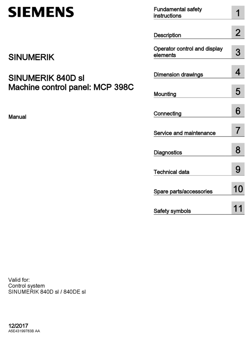
ounting the PPS-10 to the P K-1 Bracket
1. First, slide the PPS-10M module board down through the
opening slot in the PMK-1 mounting bracket with the terminal
blocks facing out, as shown in Figure 5.
2. Then reverse direction and slide the PPS-10M upward so that the
locating tabs protrude through the slots of the bracket, as shown
in Figure 6.
3. Fasten the board to the mounting bracket in three places using
the screws provided (See Figure 6).
Figure 4
PPS-10M Module Board
NOTES:
When two Model PPS-10M power supplies are used in a PXL System:
1. Cut Jumper JP3 on the se ond PPS-10M.
2. Disable TB5 on the se ond PPS-10M.
3. Cut and remove the red wires from the 15" able in the PCK-1 kit
(P/N 500-695066) when onne ting between the two PPS-10Ms.
4. Refer to Appendix E for abling onne tions in a PSE-2 En losure.
Technical Manuals Online! - http://www.tech-man.com
firealarmresources.com
InstallationPXL Conventional FireAlarm Control Panel
11
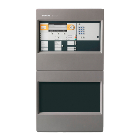
Figure 5
Sliding the PPS-10M into the PMK-1 Bracket
Figure 6
Mounting the PPS-10M on the PMK-1 Bracket
Technical Manuals Online! - http://www.tech-man.com
firealarmresources.com
PXL Conventional FireAlarm Control Panel Installation
12
STEP 4Install the Optional PRM-4
CAUTION
The PPS-10M Power Supply module must be installed be ore
mounting and wiring the PRM-4 Relay module.
Setting the Address
Before mounting the PRM-4 to the PMK-1 bracket, set the address on
Switch S1 according to Table 2. (Refer to Figure 7 for the location of S1
and to the Note on page 9 for the operation of the switches.)
TABLE 2
SETTING THE ADDRESS ON THE PRM-4
Module
Number Relay
Range Switch Setting
1 2 3 4 5
11-4 X O O O O
25-8 O X O O O
39-12 X X O O O
413-16 O O X O O
517-20 X O X O O
621-24 O X X O O
725-28 X X X O O
829-32 O O O X O
X = SWITCH CLOSED OR ON, O = SWITCH OPEN OR OFF
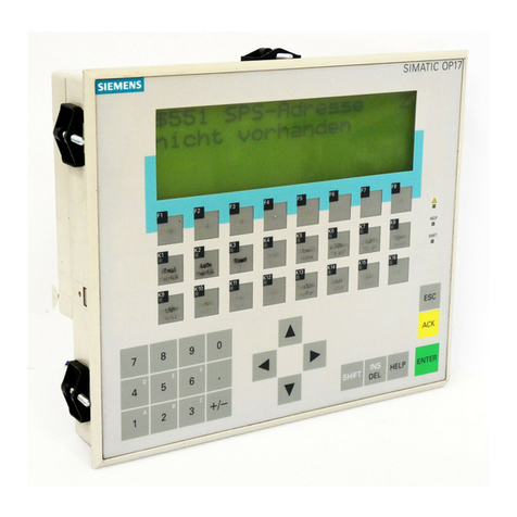
Figure 7
PRM-4 Module Board
Technical Manuals Online! - http://www.tech-man.com
firealarmresources.com
InstallationPXL Conventional FireAlarm Control Panel
13
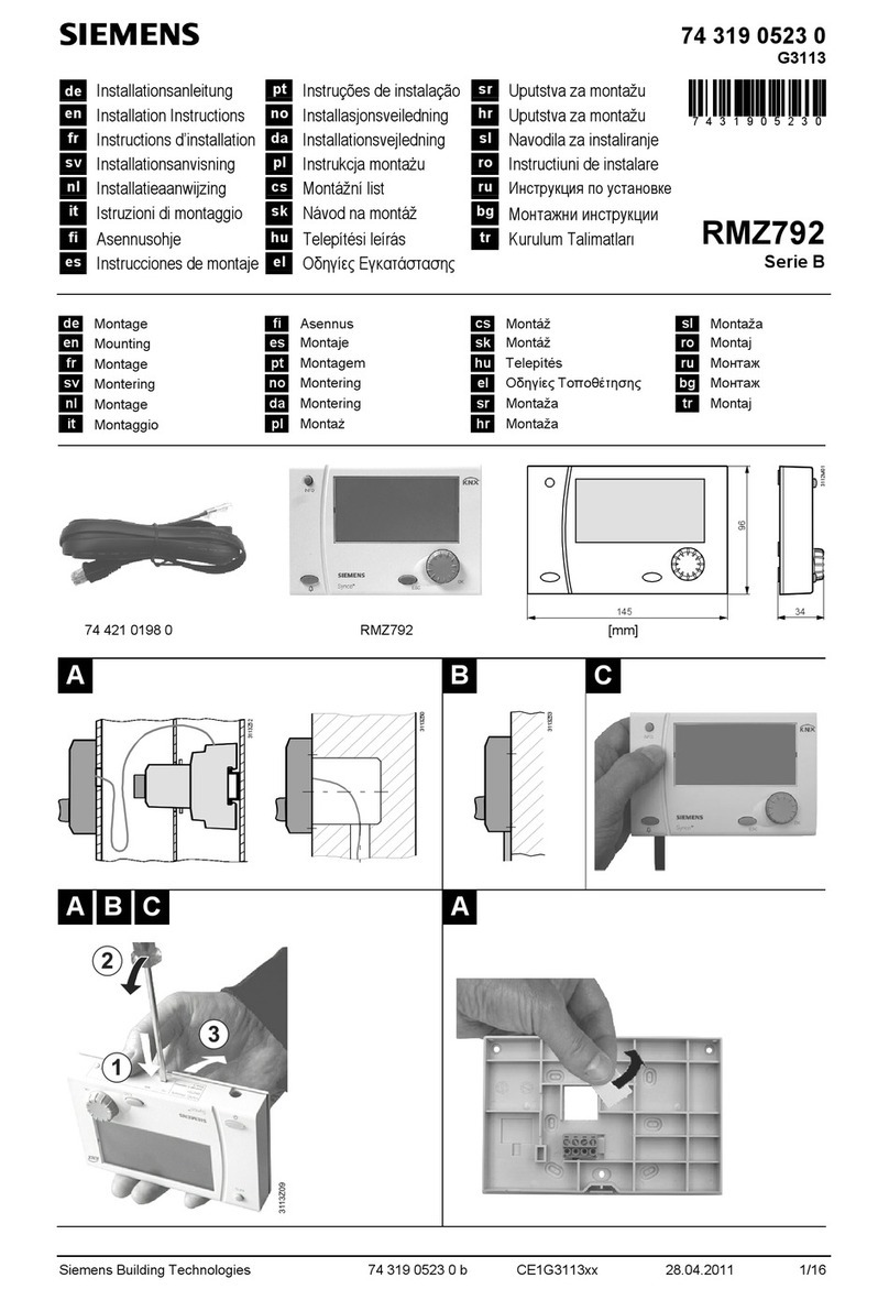
ounting the PR -4
1. Slide the PRM-4 module board through the slot in the PMK-1
mounting bracket next to the PPS-10M with the terminal blocks
facing out and the locating tab protruding through the slot of the
bracket, as shown in Figure 8.
2. Fasten the board to the mounting bracket with the screw provided
(See Figure 8).
Figure 8
Mounting the PRM-4 on the PMK-1 Bracket
Technical Manuals Online! - http://www.tech-man.com
firealarmresources.com
PXL Conventional FireAlarm Control Panel Installation
14
STEP 5Install the Optional PNC-2Z
CAUTION
The PPS-10M Power Supply module must be installed be ore
mounting and wiring the PNC-2Z noti ication module.
Setting the Address
Before mounting the
PNC-2Z
to the PMK-1 bracket, set the address on
Switch S1 according to Table 3. (Refer to Figure 9 for the location of S1 and
to the Note on page 9 for the operation of the switches.)
X = SWITCH CLOSED OR ON, O = SWITCH OPEN OR OFF
Figure 9
PNC-2Z Module Board
TABLE 3
SETTING THE ADDRESS ON THE
PNC-2Z
Module
Number NAC
Range Switch Setting
1 2 3 4 5
1 9-10 X O O O O
2 11-12 O X O O O
3 13-14 X X O O O
4 15-16 O O X O O
Technical Manuals Online! - http://www.tech-man.com

firealarmresources.com

Other Siemens Control Panel manuals

Siemens SIMATIC HMI series User manual

Siemens

Siemens SIMATIC HMI series User manual

Siemens SIMATIC Mobile Panel 277 IWLAN User guide

Siemens

Siemens SIMATIC Mobile Panel 277 IWLAN User guide

Siemens FC361-ZZ User manual

Siemens

Siemens FC361-ZZ User manual

Siemens IVK-6 User manual

Siemens

Siemens IVK-6 User manual

Siemens LED-3 User manual

Siemens

Siemens LED-3 User manual

Siemens MJ-X User manual

Siemens

Siemens MJ-X User manual

Siemens SINAMICS Series User manual

Siemens

Siemens SINAMICS Series User manual

Siemens SINUMERIK 840D sl OP 010 User manual

Siemens

Siemens SINUMERIK 840D sl OP 010 User manual

Siemens MCP 398C User manual

Siemens

Siemens MCP 398C User manual

Siemens FC2005 User manual

Siemens

Siemens FC2005 User manual

Siemens SIMATIC HMI OP3 Technical Document

Siemens

Siemens SIMATIC HMI OP3 Technical Document

Siemens SPC 4300 User manual

Siemens

Siemens SPC 4300 User manual

Siemens FC10 User manual

Siemens

Siemens FC10 User manual

Siemens Multi Panel MP270 SIMATIC HMI Technical Document

Siemens

Siemens Multi Panel MP270 SIMATIC HMI Technical Document

Siemens OP7 Technical Document

Siemens

Siemens OP7 Technical Document

Siemens SIMATIC WinCC flexible 2008 SP4 User guide

Siemens

Siemens SIMATIC WinCC flexible 2008 SP4 User guide

Siemens SIMATIC HMI SICALIS PMC 7 Technical Document

Siemens

Siemens SIMATIC HMI SICALIS PMC 7 Technical Document

Siemens SIMATIC HMI KP400 Comfort User manual

Siemens

Siemens SIMATIC HMI KP400 Comfort User manual

Siemens SINUMERIK MCP-S Series Technical Document

Siemens

Siemens SINUMERIK MCP-S Series Technical Document

Siemens GENESIS II User manual

Siemens

Siemens GENESIS II User manual

Siemens SINUMERIK 802D sl User manual

Siemens

Siemens SINUMERIK 802D sl User manual

Siemens simatic hmi op27 Technical Document

Siemens

Siemens simatic hmi op27 Technical Document

Siemens FC123-ZA User manual

Siemens

Siemens FC123-ZA User manual

Siemens SIMATIC HMI 177 User manual

Siemens

Siemens SIMATIC HMI 177 User manual

Popular Control Panel manuals by other brands

Spirax Sarco Universal Lite Control Panel Installation and maintenance instructions

Spirax Sarco

Spirax Sarco Universal Lite Control Panel Installation and maintenance instructions

Honeywell NOTIFIER ID62 installation, commissioning & configuration manual

Honeywell

Honeywell NOTIFIER ID62 installation, commissioning & configuration manual

Mami Mini TRACER manual

Mami

Mami Mini TRACER manual

NAPCO Magnum Alert 1016e installation instructions

NAPCO

NAPCO Magnum Alert 1016e installation instructions

Energenie EG-PWC-PSWRC-01 user manual

Energenie

Energenie EG-PWC-PSWRC-01 user manual

Groupe Atlantic NAVISTEM B2000 General instruction for installation use and maintenance

Groupe Atlantic

Groupe Atlantic NAVISTEM B2000 General instruction for installation use and maintenance

DSC PowerSeries PC1616 user manual

DSC

DSC PowerSeries PC1616 user manual

Citron REfire SC-TK3-2.8 instruction manual

Citron

Citron REfire SC-TK3-2.8 instruction manual

Bosch Rexroth IndraControl VCP 20 Project planning manual

Bosch

Bosch Rexroth IndraControl VCP 20 Project planning manual

Intermatic T21000R SERIES Installation, operation & service manual

Intermatic

Intermatic T21000R SERIES Installation, operation & service manual

Radionics D279A user guide

Radionics

Radionics D279A user guide

Simplex 4100ES-S1 Programming guide

Simplex

Simplex 4100ES-S1 Programming guide

Salto XS4 Reader installation guide

Salto

Salto XS4 Reader installation guide

Moeller MV4 Series Hardware and engineering

Moeller

Moeller MV4 Series Hardware and engineering

Chamberlain 880LMW quick start guide

Chamberlain

Chamberlain 880LMW quick start guide

Blue Giant Blue Genius Touch Control owner's manual

Blue Giant

Blue Giant Blue Genius Touch Control owner's manual

CommPact Wireless Intruder Control Panel Quick user guide

CommPact

CommPact Wireless Intruder Control Panel Quick user guide

Clever iCLEVER PLUS user manual

Clever

Clever iCLEVER PLUS user manual

manuals.online logo
manuals.online logoBrands
  • About & Mission
  • Contact us
  • Privacy Policy
  • Terms and Conditions

Copyright 2025 Manuals.Online. All Rights Reserved.