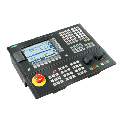
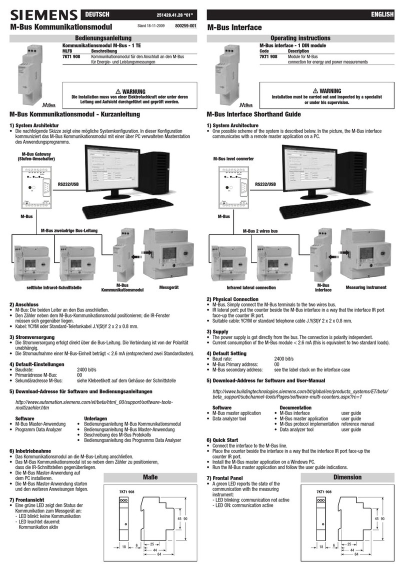
Siemens RCC-2/R User manual
Other Siemens Control Unit manuals

Siemens
Siemens SIMATIC ET 200SP User manual
Siemens
Siemens VALVEGYR LDU11.323A17 User manual
Siemens
Siemens SITRANS RD500 User manual
Siemens
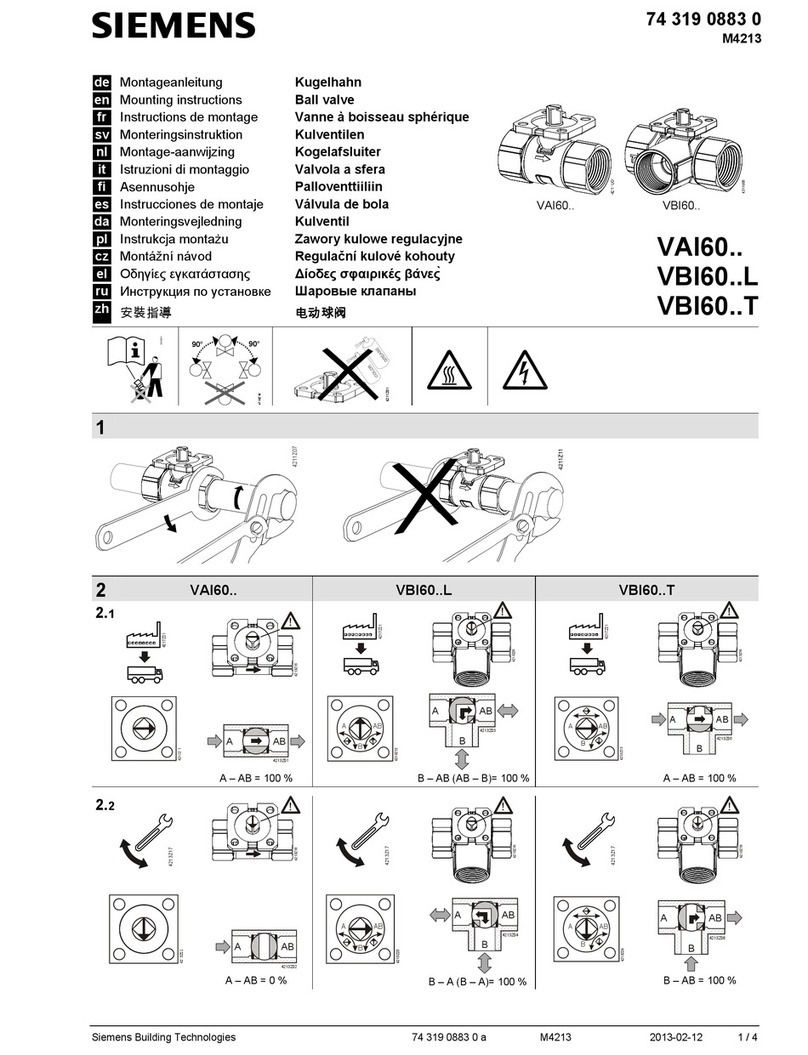
Siemens VAI60.15-15 User manual
Siemens
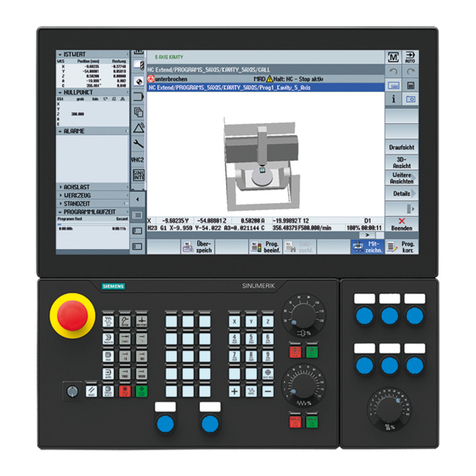
Siemens SINUMERIK 840 Technical manual

Siemens
Siemens OMM-2 User manual

Siemens
Siemens EN100 User manual

Siemens
Siemens SITRANS AW 7MP3112 Series User manual
Siemens
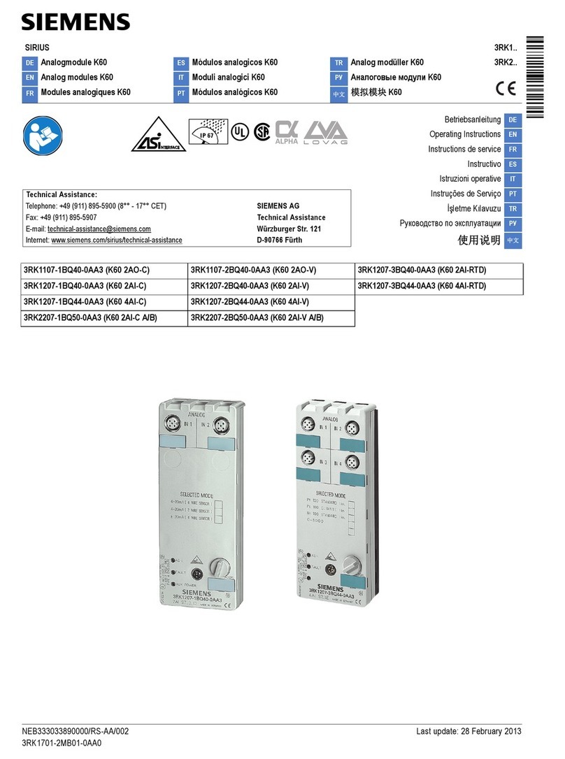
Siemens SIRIUS K60 Series User manual

Siemens
Siemens SINAMICS G120 User manual
Siemens
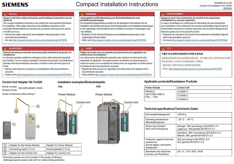
Siemens CUA20 User manual
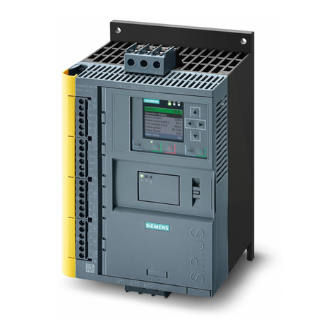
Siemens
Siemens SIRIUS 3RW5 series User manual

Siemens
Siemens SIMATIC ET 200SP User manual

Siemens
Siemens AP 118 Service manual
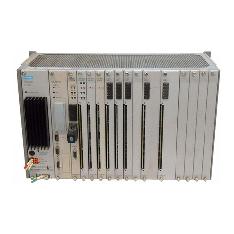
Siemens
Siemens SIMATIC TI505 User manual
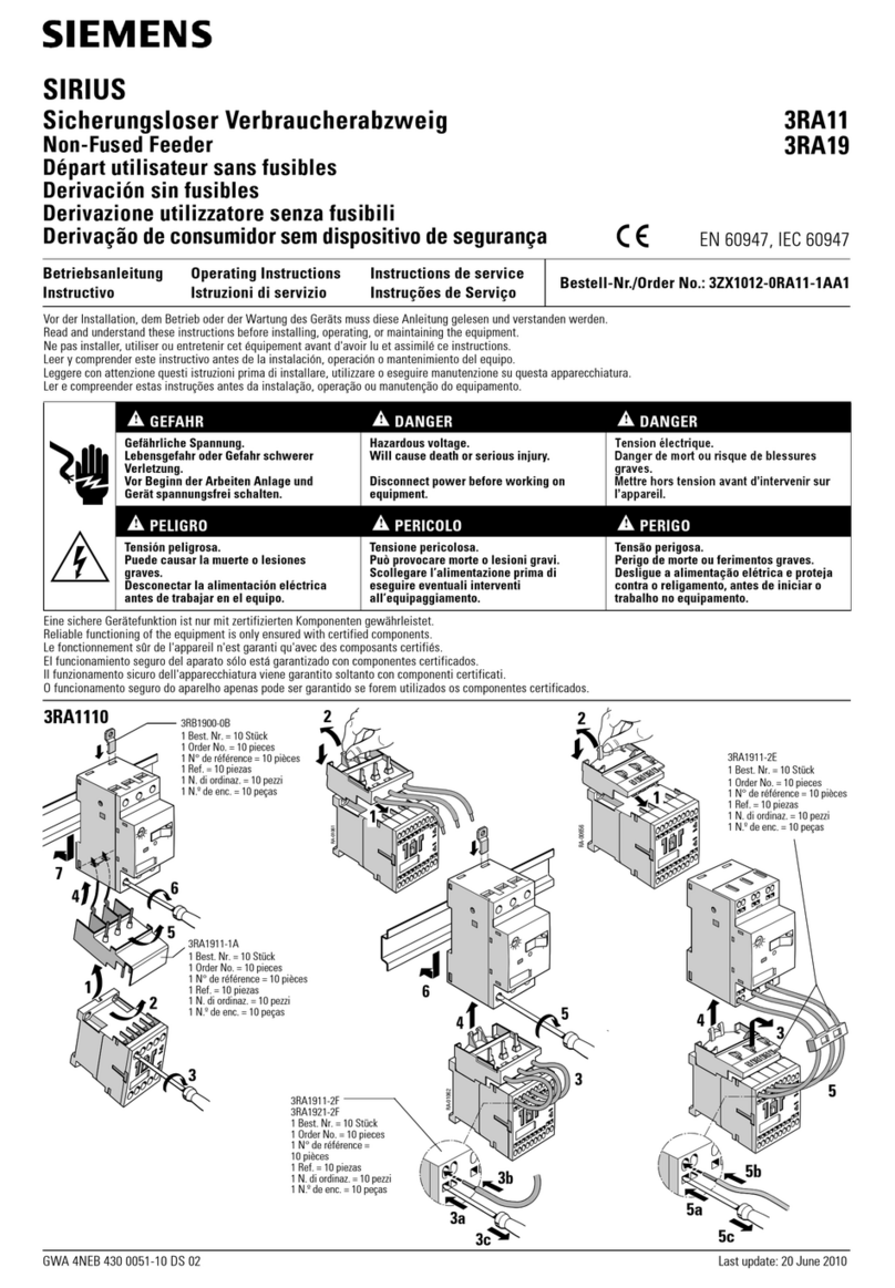
Siemens
Siemens SIRIUS 3RA11 User manual

Siemens
Siemens Simatic S7-1500 User manual

Siemens
Siemens SINAMICS SM120 Operating instructions
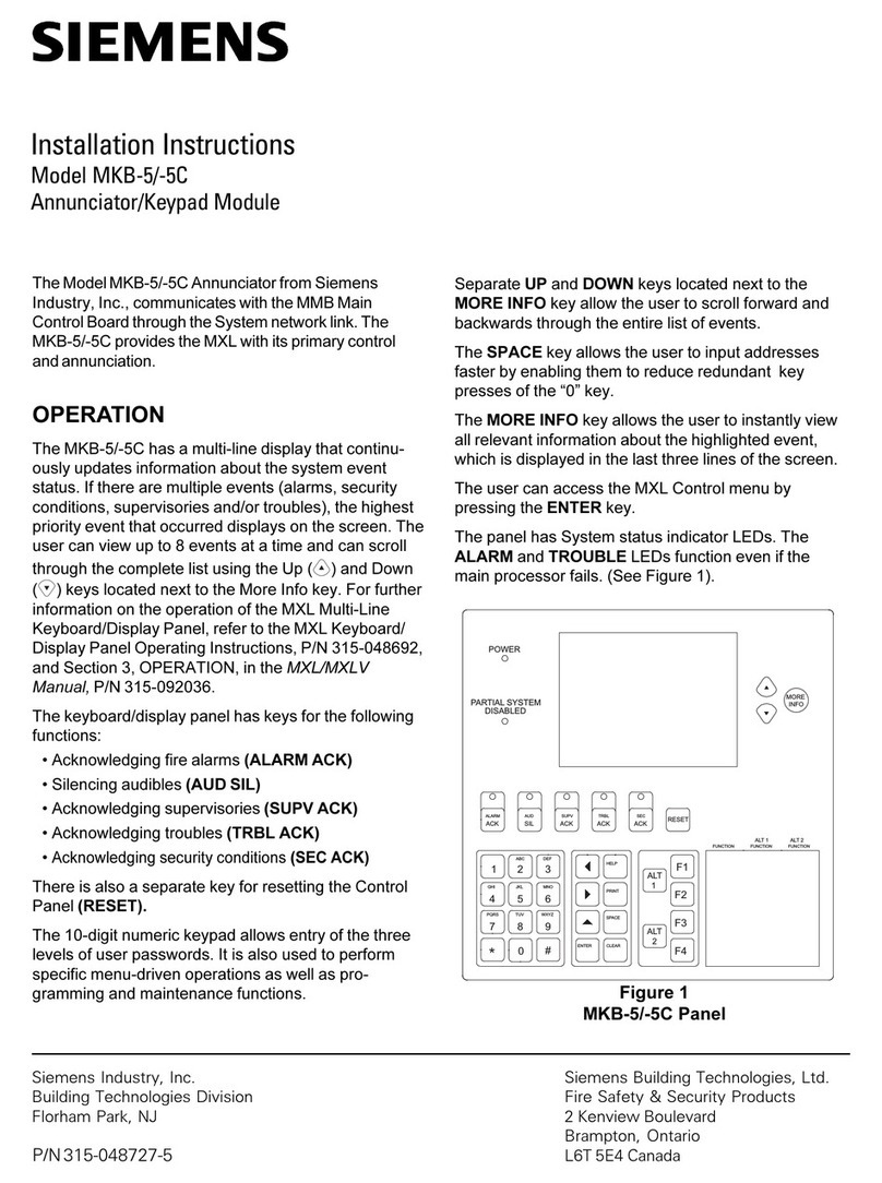
Siemens
Siemens MKB-5 User manual
Siemens
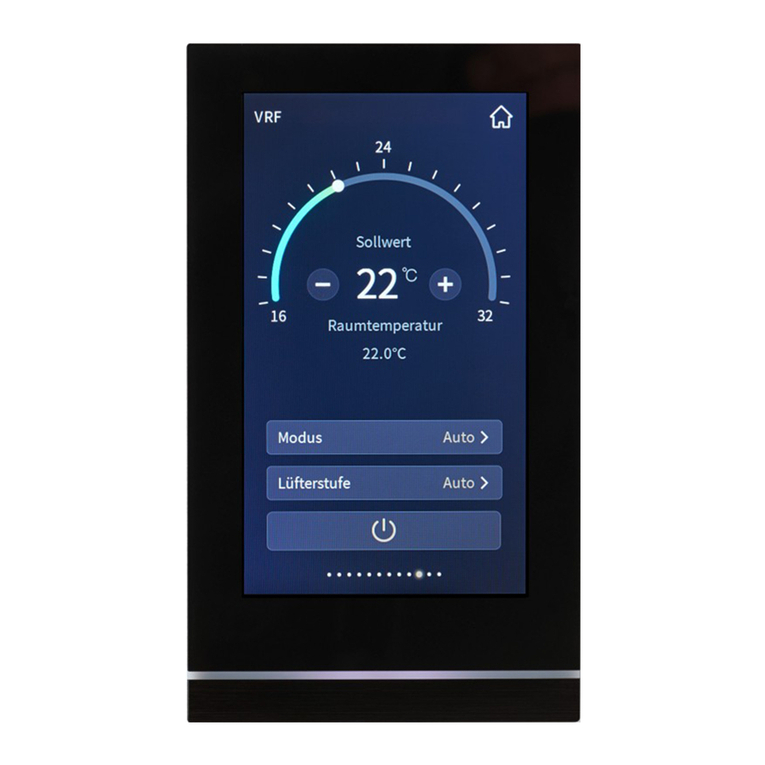
Siemens GAMMA instabus Touch control TC5 User manual
Popular Control Unit manuals by other brands

Festo
Festo Compact Performance CP-FB6-E Brief description

Elo TouchSystems
Elo TouchSystems DMS-SA19P-EXTME Quick installation guide

JS Automation
JS Automation MPC3034A user manual

JAUDT
JAUDT SW GII 6406 Series Translation of the original operating instructions

Spektrum
Spektrum Air Module System manual

BOC Edwards
BOC Edwards Q Series instruction manual

KHADAS
KHADAS BT Magic quick start

Etherma
Etherma eNEXHO-IL Assembly and operating instructions

PMFoundations
PMFoundations Attenuverter Assembly guide

GEA
GEA VARIVENT Operating instruction

Walther Systemtechnik
Walther Systemtechnik VMS-05 Assembly instructions

Altronix
Altronix LINQ8PD Installation and programming manual
