manuals.online logo
Brands
  1. Home
  2. •
  3. Brands
  4. •
  5. Siemens
  6. •
  7. Control Unit
  8. •
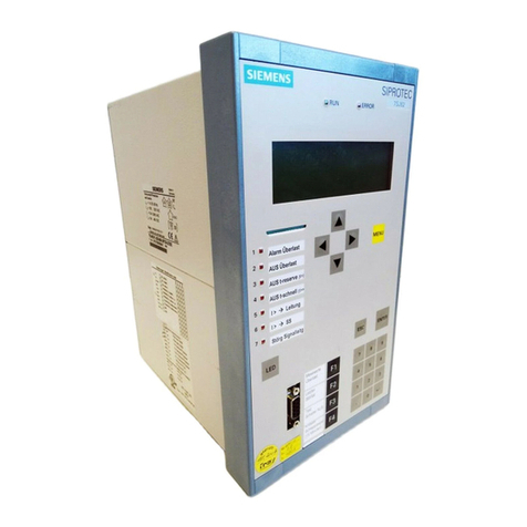
  9. Siemens SIPROTEC 7VE61 User manual

Siemens SIPROTEC 7VE61 User manual

Revision 1.0
Edition: July 2003
C53000-L1840-C017-03
SIPROTEC
Multifunction Paralleling
Devices
7VE61, 7VE63
Communication module
Modbus
Bus mapping
3UHIDFH
7DEOHRIFRQWHQWV
0RGEXVUHJLVWHUPDS 1
,QGH[
Siemens Aktiengesellschaft
C53000-L1840-C017-03
/LDELOLW\VWDWHPHQW
We have checked the contents of this manual against the
hardware and software described. Exclusions and devia-
tions cannot be ruled out; we accept no liability for lack of
total agreement.
The information in this manual is checked periodically,
and necessary corrections will be included in future
editions.
We appreciate any suggested improvements.
We reserve the right to make technical improvements
without notice.
&RS\ULJKW
Copyright © Siemens AG 2003. All rights reserved.
Dissemination or reproduction of this document, or evaluation and commu
-
nication of its contents, is not authorized except where expressly permitted
.
Violations are liable for damages. All rights reserved, particularly for the
purposes of patent application or trademark registration.
5HJLVWHUHGWUDGHPDUNV
SIPROTEC®and DIGSI®are registered trademarks of Siemens AG.
Modbus and Modbus Plus are trademarks of Modicon, Inc.
Other designations in this manual may be trademarks that if used by third
parties for their own purposes may violate the rights of the owner.
iSIPROTEC Modbus - Bus mapping 7VE61, 7VE63
C53000-L1840-C017-03
3UHIDFH
3XUSRVHRIWKLV
PDQXDO
The manual describes the register map organization of the Modbus slave of the
SIPROTEC devices 7VE61, 7VE63 and is devided into the following topics:
•Modbus register map →Chapter 1.
General details about the function, operation, assembly and commissioning of the
SIPROTEC devices you find in the
•SIPROTEC4 System Manual, order no. E50417–H1176–C151.
0RGEXV
FRPPXQLFDWLRQ
SURILOH
GRFXPHQWDWLRQ
The following additional manual informs you about the data types, bus specific param-
eters and hardware inteface of the Modbus slave modul of the SIPROTEC devices:
0RGEXV
VSHFLILFDWLRQ
The Modbus specification with a detailed explanation of the Modbus protocol is
contained in:

MODICON
Modbus Protocol
Reference Guide
PI-MBUS-300 Rev. J
June 1996, Modicon, Inc.
0DQXDO 2UGHUQXPEHU
SIPROTEC Communication module,
Modbus - Communication profile C53000-L1840-C001-03
3UHIDFH
ii SIPROTEC Modbus - Bus mapping 7VE61, 7VE63
C53000-L1840-C017-03
9DOLGLW\ This manual is valid for the SIPROTEC devices:
•7VE61, 7VE63 (firmware version 4.0 or higher),
with
•Modbus communication module version 03.00.04 or higher.
For device parameterization have to be used:
•DIGSI 4.3 or higher,
•Modbus standard mappings 3-n
(n = device type dependent number of standard mappings).
$GGLWLRQDO6XSSRUW For questions regarding SIPROTEC4 devices, please contact your Siemens repre-
sentative.
7UDLQLQJFRXUVHV Individual course offerings may be found in our Training Catalog and questions can be
directed to our Training Centre. Please contact your Siemens representative.
7DUJHWDXGLHQFH Protection engineers, commissioning engineers, personnel concerned with adjust-
ment, checking and service of selective protective equipment, automatic and control
facilities and personnel of electrical facilities and power plants.
3UHIDFH
iii
SIPROTEC Modbus - Bus mapping 7VE61, 7VE63
C53000-L1840-C017-03
48$/,),('3(56211(/
Within the meaning of safety precautions of this manual and the instructions, qualified
personnel are those persons who are qualified to set up, install, place into service, and
operate this device, and who possess the following qualifications:
•Training and instruction (or other qualification) for switching, grounding, and desig-
nating devices and systems.
•Training or instruction in accordance with safety standards for care and use of cer-
tain safety equipment.
First aid training.
7\SRJUDSKLFDQG
JUDSKLFDOFRQYHQ
WLRQV
The following text formats are used to identify concepts giving device information de-
scribed by the text flow:
3DUDPHWHUQDPHV, or identifiers for configuration or function parameters that appear
in the device display or on the screen of a PC (with DIGSI) are shown in mono-script
(same point size) bold text. This also applies to header bars for selection menus.
3DUDPHWHUFRQGLWLRQV, or possible settings of parameters that appear in the de-
vice display or on the screen of a PC (with DIGSI), are additionally shown in italic style.
This also applies to selection items for selection menus.
„$QQXQFLDWLRQV“, or identifiers for information produced by the device or required
by other devices or from the switchgear is shown in mono-script (same point size) and
placed into quotation marks.
For diagrams in which the identifier type results from the representation itself, text con-
ventions may differ from the above-mentioned.
:DUQLQJ
During operation of electrical equipment, certain parts of these devices are under high
voltage. Severe personal injury or significant equipment damage could result from
improper behaviour.
Only qualified personnel should work on this equipment or in the vicinity of this equip-
ment. These personnel must be familiar with all warnings and service procedures
described in this manual, as well as with safety regulations.
Prerequisites to proper and safe operation of this product are proper transport, proper
storage, setup, installation, operation, and maintenance of the product, as well as
careful operation and servicing of the device within the scope of the warnings and
instructions of this manual.
In particular, the general facility and safety regulations for work with high-voltage
equipment (e.g. ANSI, IEC, EN, or other national or international regulations) must be
observed. Noncompliance may result in death, injury or significant equipment
damage.
3UHIDFH
iv SIPROTEC Modbus - Bus mapping 7VE61, 7VE63
C53000-L1840-C017-03
vSIPROTEC Modbus - Bus mapping 7VE61, 7VE63
C53000-L1840-C017-03
HYLVLRQLQGH[
Listing of the changes between the editions of this manual:
0RGLILHGFKDSWHUV
SDJHV (GLWLRQ HDVRQVRIPRGLILFDWLRQ
1.0 First edition, Doc.-No.: C53000-L1840-C017-03
July 30th, 2003
5HYLVLRQLQGH[
vi SIPROTEC Modbus - Bus mapping 7VE61, 7VE63
C53000-L1840-C017-03
viiSIPROTEC Modbus - Bus mapping 7VE61, 7VE63
C53000-L1840-C017-03
7DEOHRIFRQWHQWV
3UHIDFH L
HYLVLRQLQGH[  Y
 0RGEXVUHJLVWHUPDS  
1.1 Explanations........................................................................................................................1-2
1.2 Coil Status registers (0X references)................................................................................... 1-3
1.2.1 Registers 00001 to 00044: Single commands (with checkback indication)......................... 1-3
1.2.2 Registers 00045 to 00048: Internal commands...................................................................1-5
1.2.3 Registers 00049 to 00052: Double commands (with checkback indication) ....................... 1-6
1.2.4 Registers Registers 00257 to 00264: Exception Flags........................................................ 1-6
1.3 Input Status registers (1X references).................................................................................1-7
1.3.1 Registers 10001 to 10016: Single-point indications, taggings............................................. 1-7
1.3.2 Registers 10017 to 10029: Error messages synchronization.............................................. 1-8
1.3.3 Registers 10030 to 10095: Synchronization........................................................................ 1-8
1.4 Input registers (3X references).......................................................................................... 1-11
1.5 Holding registers (4X references)......................................................................................1-12
1.5.1 Registers 40001 to 40036: System information................................................................. 1-12
1.5.2 Registers 40065 to 40069: Time synchronization ............................................................. 1-13
1.5.3 Register 40129: Diagnosis ................................................................................................ 1-14
1.5.4 Registers 40301 to 40316: Statistic values ....................................................................... 1-15
1.5.5 Registers 40351 to 40520: Min/Max values of measured values...................................... 1-16
1.5.6 Registers 40601 to 40626: Event recorder (Sequence of Events).................................... 1-17
*ORVVDU\  
,QGH[  
7DEOHRIFRQWHQWV
viii SIPROTEC Modbus - Bus mapping 7VE61, 7VE63
C53000-L1840-C017-03
1-1SIPROTEC Modbus - Bus mapping 7VE61, 7VE63
C53000-L1840-C017-03
0RGEXVUHJLVWHUPDS 
This chapter describes the register map organization of the Modbus slave of the
SIPROTEC devices 7VE61, 7VE63.
1.1 Explanations 1-2
1.2 Coil Status registers (0X references) 1-3
1.3 Input Status registers (1X references) 1-7
1.4 Input registers (3X references) 1-11
1.5 Holding registers (4X references) 1-12
0RGE VUHJLVWHUPDS
1-2 SIPROTEC Modbus - Bus mapping 7VE61, 7VE63
C53000-L1840-C017-03
 ([SODQDWLRQV
Chapters 1.2 to 1.5 define the mapping of the data objects of the SIPROTEC devices
7VE61, 7VE63 to the associated Modbus registers.
The columns "Designation of the SIPROTEC objects" contain the texts of the SIPRO-
TEC objects for 86(QJOLVK device language.
The listed SIPROTEC data objects are VRUWHGE\UHJLVWHUQ PEHUV (starting with 1),
e.g.:
The measured value 9 is assigned to register 30001 (Input register).
Thesingle-pointindication ´0RQ7LPH([Fµ isassigned to theInputStatusregister
10017.
1RWH
The examples shown in this chapter 1.1 do not necessarily correspond to the real allo-
cation of the objects in the register mapping.
HJLVWHU 'HVLJQDWLRQRIWKH
6,3 27(&REMHFWV &RPPHQWV 6FDOLQJ
FRUUHVSRQGVWR
,QWHUQDO
REMHFWQR
30001 V1 = Measured value V1 3276,7 V 25044
HJLVWHU 'HVLJQDWLRQRIWKH
6,3 27(&REMHFWV &RPPHQWV ,QWHUQDO
REMHFWQR
10017 25 MonTimeExc 1 = 25 Monitoring time exceeded 222.2025.01
1RWH
•The description of the standard mappings contains the pre-allocation of the map-
ping files DWGHOLYHU\RUDWILUVWDVVLJQPHQW of a mapping in DIGSI to the SIPROTEC
device.
•Changes of the allocation and the scaling of the measured values are possible in
adaptation to the concrete installation enviroment.
You find information about this in the manual "SIPROTEC Communication module,
Modbus - Communication profile" (ref. to page i).
•The definition of the data types (single-point indication, measured value etc.) are
contained in the manual "SIPROTEC Communication module, Modbus - Commu-
nication profile" (ref. to page i).
0RGE VUHJLVWHUPDS
1-3
SIPROTEC Modbus - Bus mapping 7VE61, 7VE63
C53000-L1840-C017-03
 &RLO6WDWXVUHJLVWHUV;UHIHUHQFHV
The Coil Status register block allows the Modbus master:
•command outputs through the output relays of the SIPROTEC device (external
commands),
•manipulation of taggings (internal commands),
•reading the checkback indication and/or the status of output relays as well as
taggings.
 HJLVWHUVWR6LQJOHFRPPDQGVZLWKFKHFNEDFNLQGLFDWLRQ
•User-defined singlecommandswith checkbackindication or taggings canberouted
on these position as “Source/Destination system interface” using the ',*6,&RQ
ILJXUDWLRQPDWUL[.
1RWH
•The allocation of the output relays to the switching devices and to the output
channels is defined during parameterization of the SIPROTEC devices.
•Depending on the device composition there may be less than indicated output
relays (and corresponding Modbus registers) available in the SIPROTEC device.
HJLVWHU 'HVLJQDWLRQRIWKH
6,3 27(&REMHFWV &RPPHQWV ,QWHUQDO
REMHFWQR
00001 <user-defined> not pre-allocated -
00002 <user-defined> not pre-allocated -
00003 <user-defined> not pre-allocated -
00004 <user-defined> not pre-allocated -
00005 <user-defined> not pre-allocated -
00006 <user-defined> not pre-allocated -
00007 <user-defined> not pre-allocated -
00008 <user-defined> not pre-allocated -
00009 <user-defined> not pre-allocated -
00010 <user-defined> not pre-allocated -
00011 <user-defined> not pre-allocated -
00012 <user-defined> not pre-allocated -
00013 <user-defined> not pre-allocated -
00014 <user-defined> not pre-allocated -
00015 <user-defined> not pre-allocated -
00016 <user-defined> not pre-allocated -
00017 <user-defined> not pre-allocated -
00018 <user-defined> not pre-allocated -
00019 <user-defined> not pre-allocated -
0RGE VUHJLVWHUPDS
1-4 SIPROTEC Modbus - Bus mapping 7VE61, 7VE63
C53000-L1840-C017-03
00020 <user-defined> not pre-allocated -
00021 <user-defined> not pre-allocated -
00022 <user-defined> not pre-allocated -
00023 <user-defined> not pre-allocated -
00024 <user-defined> not pre-allocated -
00025 <user-defined> not pre-allocated -
00026 <user-defined> not pre-allocated -
00027 <user-defined> not pre-allocated -
00028 <user-defined> not pre-allocated -
00029 <user-defined> not pre-allocated -
00030 <user-defined> not pre-allocated -
00031 <user-defined> not pre-allocated -
00032 <user-defined> not pre-allocated -
00033 <user-defined> not pre-allocated -
00034 <user-defined> not pre-allocated -
00035 <user-defined> not pre-allocated -
00036 <user-defined> not pre-allocated -
00037 <user-defined> not pre-allocated -
00038 <user-defined> not pre-allocated -
00039 <user-defined> not pre-allocated -
00040 <user-defined> not pre-allocated -
00041 <user-defined> not pre-allocated -
00042 <user-defined> not pre-allocated -
00043 <user-defined> not pre-allocated -
00044 <user-defined> not pre-allocated -
HJLVWHU 'HVLJQDWLRQRIWKH
6,3 27(&REMHFWV &RPPHQWV ,QWHUQDO
REMHFWQR
0RGE VUHJLVWHUPDS
1-5
SIPROTEC Modbus - Bus mapping 7VE61, 7VE63
C53000-L1840-C017-03
 HJLVWHUVWR,QWHUQDOFRPPDQGV
HJLVWHU 'HVLJQDWLRQRIWKH
6,3 27(&REMHFWV &RPPHQWV ,QWHUQDO
REMHFWQR
00045 Command: Setting Group A 0 = not permitted
1 = Activation of setting group A -
Indication: Setting Group A 0 = Setting group A is not active
1 = Setting group A is active
00046 Command: Setting Group B 0 = not permitted
1 = Activation of setting group B -
Indication: Setting Group B 0 = Setting group B is not active
1 = Setting group B is active
00047 Command: Setting Group C 0 = not permitted
1 = Activation of setting group C -
Indication: Setting Group C 0 = Setting group C is not active
1 = Setting group C is active
00048 Command: Setting Group D 0 = not permitted
1 = Activation of setting group D -
Indication: Setting Group D 0 = Setting group D is not active
1 = Setting group D is active
&KDQJLQJWKHVHWWLQJJUR S
•In order to change the setting group, the value "1" = ON must be transmitted to the
corresponding register.
•Switching ON one setting group automatically switches OFF the current active set-
ting group.
•Transmission of the value "0" = OFF is insignificant for the change of the setting
group and is refused by the device.
1RWH
A change of the setting group is only possible via Modbus if the parameter &KDQJH
WR$QRWKHU6HWWLQJ*URXS (parameter address = 302) has the value 3URWRFRO.
0RGE VUHJLVWHUPDS
1-6 SIPROTEC Modbus - Bus mapping 7VE61, 7VE63
C53000-L1840-C017-03
 HJLVWHUVWR'RXEOHFRPPDQGVZLWKFKHFNEDFNLQGLFDWLRQ
•User-defined double commands with double-point indication as checkback indica-
tion can be routed on these position as “Source/Destination system interface” using
the ',*6,&RQILJXUDWLRQPDWUL[.
•Ref. to chap. “Double command / Double-point indication” in the manual “SIPRO-
TEC Communicationmodule,Modbus- Communicationprofile”foradditionalnotes
regarding controlling of double commands.
 HJLVWHUV HJLVWHUVWR([FHSWLRQ)ODJV
•Registers are write-protected.1
•The contents of these registers is also readable using function "Read Exception
Status" (function code 7).
•Installation-specific SIPROTEC objects can be routed on these register positions
using parameterization system DIGSI.
HJLVWHU 'HVLJQDWLRQRIWKH
6,3 27(&REMHFWV &RPPHQWV ,QWHUQDO
REMHFWQR
00049 <user-defined> ON not pro-allocated -
00050 <user-defined> OFF
00051 <user-defined> ON not pro-allocated -
00052 <user-defined> OFF
1. A write access is rejected with exception code 03 (ILLEGAL_DATA_VALUE).
HJLVWHU 'HVLJQDWLRQRIWKH
6,3 27(&REMHFWV &RPPHQWV ,QWHUQDO
REMHFWQR
00257 <user-defined> not pre-allocated -
00258 <user-defined> not pre-allocated -
00259 <user-defined> not pre-allocated -
00260 <user-defined> not pre-allocated -
00261 <user-defined> not pre-allocated -
00262 <user-defined> not pre-allocated -
00263 <user-defined> not pre-allocated -
00264 <user-defined> not pre-allocated -
0RGE VUHJLVWHUPDS
1-7
SIPROTEC Modbus - Bus mapping 7VE61, 7VE63
C53000-L1840-C017-03
 ,QSXW6WDWXVUHJLVWHUV;UHIHUHQFHV
The Input Status register block allows the Modbus master to scan the current status
of the input channels as well as the annunciations generated in the SIPROTEC device
(e.g. protection annunciations, status annunciations).
 HJLVWHUVWR6LQJOHSRLQWLQGLFDWLRQVWDJJLQJV
•Further protection annunciations, single-point indications and taggings (internal
single-point indications) can be routed on these register positions as “Destination
system interface” using the ',*6,&RQILJXUDWLRQPDWUL[.
1RWH
•The allocation of the input channels to the binary inputs is defined during parame-
terization of the devices.
•Depending on the device composition and the existing protection packages not all
of the indicated binary inputs or protection annunciations (and corresponding Mod-
bus registers) may be available in the SIPROTEC device.
HJLVWHU 'HVLJQDWLRQRIWKH
6,3 27(&REMHFWV &RPPHQWV ,QWHUQDO
REMHFWQR
10001 <user-defined> not pre-allocated -
10002 <user-defined> not pre-allocated -
10003 <user-defined> not pre-allocated -
10004 <user-defined> not pre-allocated -
10005 <user-defined> not pre-allocated -
10006 <user-defined> not pre-allocated -
10007 <user-defined> not pre-allocated -
10008 <user-defined> not pre-allocated -
10009 <user-defined> not pre-allocated -
10010 <user-defined> not pre-allocated -
10011 <user-defined> not pre-allocated -
10012 <user-defined> not pre-allocated -
10013 <user-defined> not pre-allocated -
10014 <user-defined> not pre-allocated -
10015 <user-defined> not pre-allocated -
10016 <user-defined> not pre-allocated -
0RGE VUHJLVWHUPDS
1-8 SIPROTEC Modbus - Bus mapping 7VE61, 7VE63
C53000-L1840-C017-03
 HJLVWHUVWR(UURUPHVVDJHVV\QFKURQL]DWLRQ
 HJLVWHUVWR6\QFKURQL]DWLRQ
HJLVWHU 'HVLJQDWLRQRIWKH
6,3 27(&REMHFWV &RPPHQWV ,QWHUQDO
REMHFWQR
10017 25 MonTimeExc 1 = 25 Monitoring time exceeded 222.2025.01
10018 25 FG-Error 1 = 25 Multiple selection of func-groups 222.2096.01
10019 25 Fail.Conf. 1 = 25 Failure in Configuration 222.2331.01
10020 25 sup.asym. 1 = 25-supervision V1,V2 asymmetrical 222.2309.01
10021 25 sup. α1 = 25-supervision Alpha> 222.2310.01
10022 25-1 PaErr 1 = 25-group 1: Parameter not plausible 170.2097.01
10023 25-2 PaErr 1 = 25-group 2: Parameter not plausible 170.2097.02
10024 25-3 PaErr 1 = 25-group 3: Parameter not plausible 170.2097.03
10025 25-4 PaErr 1 = 25-group 4: Parameter not plausible 170.2097.04
10026 25-5 PaErr 1 = 25-group 5: Parameter not plausible 170.2097.05
10027 25-6 PaErr 1 = 25-group 6: Parameter not plausible 170.2097.06
10028 25-7 PaErr 1 = 25-group 7: Parameter not plausible 170.2097.07
10029 25-8 PaErr 1 = 25-group 8: Parameter not plausible 170.2097.08
HJLVWHU 'HVLJQDWLRQRIWKH
6,3 27(&REMHFWV &RPPHQWV ,QWHUQDO
REMHFWQR
10030 25-1 activ 1 = 25 Function group 1 is active 170.2311.01
10031 25-2 activ 1 = 25 Function group 2 is active 170.2311.02
10032 25-3 activ 1 = 25 Function group 3 is active 170.2311.03
10033 25-4 activ 1 = 25 Function group 4 is active 170.2311.04
10034 25-5 activ 1 = 25 Function group 5 is active 170.2311.05
10035 25-6 activ 1 = 25 Function group 6 is active 170.2311.06
10036 25-7 activ 1 = 25 Function group 7 is active 170.2311.07
10037 25-8 activ 1 = 25 Function group 8 is active 170.2311.08
10038 25-1 meas. 1 = 25-group 1: measurement in progress 170.2022.01
10039 25-2 meas. 1 = 25-group 2: measurement in progress 170.2022.02
10040 25-3 meas. 1 = 25-group 3: measurement in progress 170.2022.03
10041 25-4 meas. 1 = 25-group 4: measurement in progress 170.2022.04
10042 25-5 meas. 1 = 25-group 5: measurement in progress 170.2022.05
10043 25-6 meas. 1 = 25-group 6: measurement in progress 170.2022.06
10044 25-7 meas. 1 = 25-group 7: measurement in progress 170.2022.07
10045 25-8 meas. 1 = 25-group 8: measurement in progress 170.2022.08
10046 25-1 BLOCK 1 = 25-group 1 is BLOCKED 170.0051.01
10047 25-2 BLOCK 1 = 25-group 2 is BLOCKED 170.0051.02
0RGE VUHJLVWHUPDS
1-9
SIPROTEC Modbus - Bus mapping 7VE61, 7VE63
C53000-L1840-C017-03
10048 25-3 BLOCK 1 = 25-group 3 is BLOCKED 170.0051.03
10049 25-4 BLOCK 1 = 25-group 4 is BLOCKED 170.0051.04
10050 25-5 BLOCK 1 = 25-group 5 is BLOCKED 170.0051.05
10051 25-6 BLOCK 1 = 25-group 6 is BLOCKED 170.0051.06
10052 25-7 BLOCK 1 = 25-group 7 is BLOCKED 170.0051.07
10053 25-8 BLOCK 1 = 25-group 8 is BLOCKED 170.0051.08
10054 25 V1>V2< 1 = 25 Condition V1> V2< fulfilled 222.2027.01
10055 25 V1<V2> 1 = 25 Condition V1< V2> fulfilled 222.2028.01
10056 25 V1<V2< 1 = 25 Condition V1< V2< fulfilled 222.2029.01
10057 25 Vdiff ok 1 = 25 Voltage difference (Vdiff) okay 222.2030.01
10058 25 fdiff ok 1 = 25 Frequency difference (fdiff) okay 222.2031.01
10059 25 αdiff ok 1 = 25 Angle difference (alphadiff) okay 222.2032.01
10060 25 f1>> 1 = 25 Frequency f1 > fmax permissible 222.2033.01
10061 25 f1<< 1 = 25 Frequency f1 < fmin permissible 222.2034.01
10062 25 f2>> 1 = 25 Frequency f2 > fmax permissible 222.2035.01
10063 25 f2<< 1 = 25 Frequency f2 < fmin permissible 222.2036.01
10064 25 V1>> 1 = 25 Voltage V1 > Umax permissible 222.2037.01
10065 25 V1<< 1 = 25 Voltage V1 < Umin permissible 222.2038.01
10066 25 V2>> 1 = 25 Voltage V2 > Umax permissible 222.2039.01
10067 25 V2<< 1 = 25 Voltage V2 < Umin permissible 222.2040.01
10068 25 V2>V1 1 = 25 Vdiff too large (V2>V1) 222.2090.01
10069 25 V2<V1 1 = 25 Vdiff too large (V2<V1) 222.2091.01
10070 25 f2>f1 1 = 25 fdiff too large (f2>f1) 222.2092.01
10071 25 f2<f1 1 = 25 fdiff too large (f2<f1) 222.2093.01
10072 25 α2>α1 1 = 25 alphadiff too large (α2>α1) 222.2094.01
10073 25 α2<α1 1 = 25 alphadiff too large (α2<α1) 222.2095.01
10074 25 synchron 1 1 = 25 Synchronization condition 1 okay 222.2302.01
10075 25 synchron 2 1 = 25 Synchronization condition 2 okay 222.2303.01
10076 25 CloseRel 1 1 = 25 Release of Close Command 1-1 170.2300.01
10077 25 CloseRel 2 1 = 25 Release of Close Command 2-1 170.2301.01
10078 25 CloseRel 1 1 = 25 Release of Close Command 1-2 170.2300.02
10079 25 CloseRel 2 1 = 25 Release of Close Command 2-2 170.2301.02
10080 25 CloseRel 1 1 = 25 Release of Close Command 1-3 170.2300.03
10081 25 CloseRel 2 1 = 25 Release of Close Command 2-3 170.2301.03
10082 25 CloseRel 1 1 = 25 Release of Close Command 1-4 170.2300.04
10083 25 CloseRel 2 1 = 25 Release of Close Command 2-4 170.2301.04
10084 25 CloseRel 1 1 = 25 Release of Close Command 1-5 170.2300.05
10085 25 CloseRel 2 1 = 25 Release of Close Command 2-5 170.2301.05
HJLVWHU 'HVLJQDWLRQRIWKH
6,3 27(&REMHFWV &RPPHQWV ,QWHUQDO
REMHFWQR
0RGE VUHJLVWHUPDS
1-10 SIPROTEC Modbus - Bus mapping 7VE61, 7VE63
C53000-L1840-C017-03
10086 25 CloseRel 1 1 = 25 Release of Close Command 1-6 170.2300.06
10087 25 CloseRel 2 1 = 25 Release of Close Command 2-6 170.2301.06
10088 25 CloseRel 1 1 = 25 Release of Close Command 1-7 170.2300.07
10089 25 CloseRel 2 1 = 25 Release of Close Command 2-7 170.2301.07
10090 25 CloseRel 1 1 = 25 Release of Close Command 1-8 170.2300.08
10091 25 CloseRel 2 1 = 25 Release of Close Command 2-8 170.2301.08
10092 25 V2 down 1 = 25 decrease voltage V2 222.2324.01
10093 25 V2 up 1 = 25 increase voltage V2 222.2325.01
10094 25 f2 down 1 = 25 decrease frequency f2 222.2326.01
10095 25 f2 up 1 = 25 increase frequency f2 222.2327.01
HJLVWHU 'HVLJQDWLRQRIWKH
6,3 27(&REMHFWV &RPPHQWV ,QWHUQDO
REMHFWQR

This manual suits for next models

1

Other Siemens Control Unit manuals

Siemens SINAMICS V60 User manual

Siemens

Siemens SINAMICS V60 User manual

Siemens TBM-2 User manual

Siemens

Siemens TBM-2 User manual

Siemens SINAMICS S110 Datasheet

Siemens

Siemens SINAMICS S110 Datasheet

Siemens ZIC-4AC User manual

Siemens

Siemens ZIC-4AC User manual

Siemens SINUMERIK 840D Parts list manual

Siemens

Siemens SINUMERIK 840D Parts list manual

Siemens SENTRON 7KM9300-0AM00-0AA0 User manual

Siemens

Siemens SENTRON 7KM9300-0AM00-0AA0 User manual

Siemens VN2001-A1 User manual

Siemens

Siemens VN2001-A1 User manual

Siemens FM 458-1 DP User manual

Siemens

Siemens FM 458-1 DP User manual

Siemens SINUMERIK 840D sl User manual

Siemens

Siemens SINUMERIK 840D sl User manual

Siemens SINUMERIK 840D sl User manual

Siemens

Siemens SINUMERIK 840D sl User manual

Siemens OMM-1 User manual

Siemens

Siemens OMM-1 User manual

Siemens SIMATIC ET 200S User manual

Siemens

Siemens SIMATIC ET 200S User manual

Siemens EVG4U10E Series User manual

Siemens

Siemens EVG4U10E Series User manual

Siemens SENTRON 7KM PAC 4DI/2DO User manual

Siemens

Siemens SENTRON 7KM PAC 4DI/2DO User manual

Siemens MM7000 Series User manual

Siemens

Siemens MM7000 Series User manual

Siemens MOBY I ASM 421 Parts list manual

Siemens

Siemens MOBY I ASM 421 Parts list manual

Siemens SINAMICS G120 User manual

Siemens

Siemens SINAMICS G120 User manual

Siemens V-2030 User manual

Siemens

Siemens V-2030 User manual

Siemens SIRIUS 3RW5 series Technical Document

Siemens

Siemens SIRIUS 3RW5 series Technical Document

Siemens RUGGEDCOM ROS User manual

Siemens

Siemens RUGGEDCOM ROS User manual

Siemens SIRIUS 3RA1941-1A User manual

Siemens

Siemens SIRIUS 3RA1941-1A User manual

Siemens ASIsafe SIRIUS 3RK1205-0B.00-0AA2 User manual
Siemens

Siemens ASIsafe SIRIUS 3RK1205-0B.00-0AA2 User manual

Siemens SIMATIC FM 353 User manual

Siemens

Siemens SIMATIC FM 353 User manual

Siemens Sinumerik 840DiE sl User manual

Siemens

Siemens Sinumerik 840DiE sl User manual

Popular Control Unit manuals by other brands

GiBiDi F/3 PLUS Connecting Instructions

GiBiDi

GiBiDi F/3 PLUS Connecting Instructions

Kinco HP043-20DT user manual

Kinco

Kinco HP043-20DT user manual

Honeywell NetAXS-123 installation guide

Honeywell

Honeywell NetAXS-123 installation guide

Ziton ZP3-ECU user guide

Ziton

Ziton ZP3-ECU user guide

RF-Star BM-ND04C manual

RF-Star

RF-Star BM-ND04C manual

Unex SOM-352 Series quick start guide

Unex

Unex SOM-352 Series quick start guide

Weq CFW900-7SLOTS Installation, configuration and operations guide

Weq

Weq CFW900-7SLOTS Installation, configuration and operations guide

CyberPower BP240V30ART3UTAA user manual

CyberPower

CyberPower BP240V30ART3UTAA user manual

Opengear IP Power 9258 Quick start user manual

Opengear

Opengear IP Power 9258 Quick start user manual

WAGO WAGO-I/O-SYSTEM 750-506 manual

WAGO

WAGO WAGO-I/O-SYSTEM 750-506 manual

Link 500 Series installation instructions

Link

Link 500 Series installation instructions

TECH Sinum PSZ-02 quick start guide

TECH

TECH Sinum PSZ-02 quick start guide

StepperOnline DM542S manual

StepperOnline

StepperOnline DM542S manual

Lenze L-force 9400 Series manual

Lenze

Lenze L-force 9400 Series manual

Keysight N5256A user guide

Keysight

Keysight N5256A user guide

DeDietrich GV26 manual

DeDietrich

DeDietrich GV26 manual

Massoth DiMAX 8175201 manual

Massoth

Massoth DiMAX 8175201 manual

Behringer 923 FILTERS quick start guide

Behringer

Behringer 923 FILTERS quick start guide

manuals.online logo
manuals.online logoBrands
  • About & Mission
  • Contact us
  • Privacy Policy
  • Terms and Conditions

Copyright 2025 Manuals.Online. All Rights Reserved.