manuals.online logo
Brands
  1. Home
  2. •
  3. Brands
  4. •
  5. Siemens
  6. •
  7. Controllers
  8. •
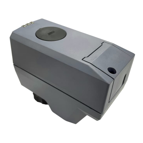
  9. Siemens OpenAir GSD 1 Series User manual

Siemens OpenAir GSD 1 Series User manual

This manual suits for next models

4

Other Siemens Controllers manuals

Siemens SINAMICS S120 Quick start guide

Siemens

Siemens SINAMICS S120 Quick start guide

Siemens 3RE4 User manual

Siemens

Siemens 3RE4 User manual

Siemens S7-1200 TELECONTROL User manual

Siemens

Siemens S7-1200 TELECONTROL User manual

Siemens RWB27 Timeswitch User manual

Siemens

Siemens RWB27 Timeswitch User manual

Siemens Flowrite 599 Series User manual

Siemens

Siemens Flowrite 599 Series User manual

Siemens 353 User manual

Siemens

Siemens 353 User manual

Siemens Stratos Outstation User manual

Siemens

Siemens Stratos Outstation User manual

Siemens GDB 9E Series User manual

Siemens

Siemens GDB 9E Series User manual

Siemens Delta Series User manual

Siemens

Siemens Delta Series User manual

Siemens SIMATIC NET MOBIC T8 User manual

Siemens

Siemens SIMATIC NET MOBIC T8 User manual

Siemens CFG3.F200 User manual

Siemens

Siemens CFG3.F200 User manual

Siemens LMV51 Series Operator's manual

Siemens

Siemens LMV51 Series Operator's manual

Siemens SITOP PSU8600 User manual

Siemens

Siemens SITOP PSU8600 User manual

Siemens Simatic S7-1500 Technical Document

Siemens

Siemens Simatic S7-1500 Technical Document

Siemens OpenAir GLB Series User manual

Siemens

Siemens OpenAir GLB Series User manual

Siemens SIRIUS 3RW44 User guide

Siemens

Siemens SIRIUS 3RW44 User guide
Siemens SINUMERIK 840D sl User manual

Siemens

Siemens SINUMERIK 840D sl User manual

Siemens SINUMERIK 840D sl Parts list manual

Siemens

Siemens SINUMERIK 840D sl Parts list manual

Siemens SIMATIC S7 User manual

Siemens

Siemens SIMATIC S7 User manual

Siemens Simatic S7-300 User manual

Siemens

Siemens Simatic S7-300 User manual

Siemens RAJA+ 3TE7111-2SC18-1A Series Operating instructions

Siemens

Siemens RAJA+ 3TE7111-2SC18-1A Series Operating instructions

Siemens SIMATIC S7-1200 Instruction Manual

Siemens

Siemens SIMATIC S7-1200 Instruction Manual

Siemens SIMATIC S5-115F User manual

Siemens

Siemens SIMATIC S5-115F User manual

Siemens SINAMICS G130 User manual

Siemens

Siemens SINAMICS G130 User manual

Popular Controllers manuals by other brands

Sunricher SR-ZV9003T3-RGBW-US Installation

Sunricher

Sunricher SR-ZV9003T3-RGBW-US Installation

Ksenia intro Installation and configuration manual

Ksenia

Ksenia intro Installation and configuration manual

Inovance CAN200 Series manual

Inovance

Inovance CAN200 Series manual

Gauzy LC6 FLEX Controller Installation and operation guide

Gauzy

Gauzy LC6 FLEX Controller Installation and operation guide

Viking SLP-1 Technical practice

Viking

Viking SLP-1 Technical practice

CKD KBX-30E-U Series instruction manual

CKD

CKD KBX-30E-U Series instruction manual

Sharp Energy Sun Flux User manual & installation guide

Sharp Energy

Sharp Energy Sun Flux User manual & installation guide

Yamaha RCX40 user manual

Yamaha

Yamaha RCX40 user manual

AB Quality PowerFlex 400 Frames D-H Service bulletin

AB Quality

AB Quality PowerFlex 400 Frames D-H Service bulletin

Yamaha MJC8 owner's manual

Yamaha

Yamaha MJC8 owner's manual

AL-KO ATC operating instructions

AL-KO

AL-KO ATC operating instructions

Savant SmartControl 2 Deployment guide

Savant

Savant SmartControl 2 Deployment guide

GameSir T3S user manual

GameSir

GameSir T3S user manual

Kostal inveor operating manual

Kostal

Kostal inveor operating manual

Emerson Yarway 20-55 Operating and safety instructions

Emerson

Emerson Yarway 20-55 Operating and safety instructions

CoCo ACM-LV24 Quick installation guide

CoCo

CoCo ACM-LV24 Quick installation guide

Brooks SLA5810/20 Installation and operation manual

Brooks

Brooks SLA5810/20 Installation and operation manual

SIGMA TEK SR 011 Technical manual

SIGMA TEK

SIGMA TEK SR 011 Technical manual

manuals.online logo
manuals.online logoBrands
  • About & Mission
  • Contact us
  • Privacy Policy
  • Terms and Conditions

Copyright 2025 Manuals.Online. All Rights Reserved.

CE2N4603en
2019-11-25
Smart Infrastructure
4603
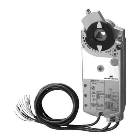
OpenAir™
Air damper actuators
GSD...1
Rotary version, AC/DC 24 V and AC 230 V
•Electric motor-driven rotary actuators for open-close control (1-wire SPST)
•2 Nm nominal torque
•AC/DC 24 V or AC 230 V rated voltage
•Prewired with 0.9 m connecting cable
•Slider for manual adjustment
•Auxiliary switch for auxiliary functions
GSD…1
2 / 9
Siemens Air damper actuators GSD...1 CE2N4603en
Smart Infrastructure 2019-11-25
Use
•For damper areas up to 0.3 m2, friction dependent.
•For directly driven zone dampers to control air flow in air ducts.
Accessories / Spare parts
•Rotation Limiter Kit ASK74.11
Type summary
Type
Operating
voltage
Control
signal
Cable
length
Shaft
diameter
Auxiliary
switch
GSD121.1A*
AC/DC 24 V
Open-close**
0.9 m
8…15 mm
-
GSD126.1A*
AC/DC 24 V
Open-close**
0.9 m
8…15 mm
yes
GSD321.1A*
AC 230 V
Open-close**
0.9 m
8…15 mm
-
GSD326.1A*
AC 230 V
Open-close**
0.9 m
8…15 mm
yes
* While stocks last
**1-wire, SPST: Single-pole, single-throw
Refer to „Internal Diagrams“, page 7.
Functions
Type
GSD121.1A
GSD126.1A
GSD321.1A
GSD326.1A
Control type
Open-close *
Rotary direction
Clockwise or counter-clockwise movement depends on the actuator's mounting
position on the damper shaft…
Slider
Pressing the slider allows for manual actuator adjustment.
Auxiliary switch
GSD...6.1A: Set switching points at 5° or 85°.
* 1-wire, SPST: Single-pole, single-throw
Technical data
Operating voltage AC / frequency
Operating voltage DC
AC 24 V ± 20% ; 50 / 60 Hz
DC 24 V ± 15%
Power consumption
GSD121.1A / GSD126.1A: (running)
(holding)
2 VA / 1.5 W
1 VA / 0.5 W
Safety extra-low voltage (SELV) or
Protective extra-low voltage (PELV) as per
HD 384
Operating voltage / Frequency
AC 230 V ± 15%; 50/60 Hz
Fuse for incoming supply line (fast)
2 A.
Power consumption
GSD321.1A / GSD326.1A: (running)
(holding)
12 VA / 2 W
12 VA / 2 W
Nominal torque
2 Nm
Maximum torque
6 Nm
Nominal rotational angle
90
Maximum rotational angle
(mechanically limited)
95 ± 2°
Runtime at nominal rotational angle 90°
30 s
Duty cycle
100%
Direction of rotation
Clockwise/counter-clockwise
Non-spring return rotary
actuators GSD
Power supply
AC/DC 24 V
Supply voltage
AC 230 V
Functional data
3 / 9
Siemens Air damper actuators GSD...1 CE2N4603en
Smart Infrastructure 2019-11-25
Mechanical life
25 000 cycles
4 / 9
Siemens Air damper actuators GSD...1 CE2N4603en
Smart Infrastructure 2019-11-25
AC –Power
−Switching voltage
−Rated voltage resistive / inductive
No mixed operation AC 24 V / 230 V
DC –Power
−Switching voltage
−Rated current
−Factory switch setting:
−Switch A (set)
−Switch B (set)
AC 24…230 V
6 A / 2 A
DC 12…30 V
DC 2 A
5°
85°
Cable length
0.9 m
Cross-section
0.75 mm2
Protection as per EN 60 529
IP40
Insulation protective class
−AC 230 V
−AC/DC 24 V
EN 60 730
Operation
−Climatic conditions
−Mounting location
−Temperature (extended)
−Humidity, non-condensing
IEC 721-3-3
Class 3K5
Interior, weather-protected
-32...+55 C
95% r.h.
Transportation
−Climatic conditions
−Temperature (extended)
−Humidity, non-condensing
IEC 721-3-2
Class 2K3
-32…+70 C
< 95% r.h.
Storage
−Climatic conditions
−Temperature (extended)
−Humidity, non-condensing
IEC 721-3-1
Class 1K3
-32…+50 C
< 95% r.h.
Mechanical conditions
Class 2M2
Product safety
Automatic electrical controls for household
and similar use
IEC/EN 60 730-2-14 (Type 1)
Electromagnetic compatibility (Application)
For residential, commercial and
industrial environments
EU Conformity (CE)
A5W00004362 1)
RCM Conformity
A5W00004363 1)
Product environmental declaration 2)
CM2E4604E 1)
Actuator
W H D
See "Dimensions”
Damper shaft
−Rectangular
Min. length
Max. shaft hardness
6…11 mm
20 mm
300 HV
−Round
Min. length
Max. shaft hardness
8…15 mm
20 mm
300 HV
Excl. packaging
−GSD..21.1A
−GSD..26.1A
0.440 kg
0.560 kg
1) The documents can be downloaded from http://siemens.com/bt/download
2) The product environmental declaration contains data on environmentally compatible product design
and assessments (RoHS compliance, materials composition, packaging, environmental benefit,
disposal).
Auxiliary switch
Connection cables
Housing type
Protection class
Environmental conditions
Standards
Dimensions
Weight
5 / 9
Siemens Air damper actuators GSD...1 CE2N4603en
Smart Infrastructure 2019-11-25
Mechanical design
Fiberglass-reinforced plastic
Maintenance-free, noise-free
Engineering notes
This section explains general and system-specific regulations for mains and
operating voltages. It also contains important information on your own safety and
that of your plant.
Use these actuators as described in the basic system documentation for the
applied control systems. In addition, take account of all actuator-specific features
and conditions as described in the brief description on the front page of this data
sheet (bold print) as well as the sections "Use", "Engineering notes", and
"Technical data".
Sections flagged with the warning symbol to the left contain safety-related
requirements and restrictions that must be adhered to at all times to prevent
physical injury and equipment damage.
Operate the actuators only on safety extra-low voltage (SELV) or protective extra-
low voltage (PELV) as per HD 384.
The actuators are double-insulated and there is no connection for the protective
ground.
Apply only mains voltage or protective extra-low voltage to the switching outputs of
the auxiliary switch. Mixed operation is not allowed. Operation at various phases is
not allowed.
Do not open the actuators!
•The actuators are maintenance-free.
•Only the manufacturer may carry out repair work.
•Opening the actuator will void the warranty.
Up to 10 actuators of the same type can be electrically wired in parallel; cable
length and cable cross-sections must be observed.
Selection of the actuator depends on several torque factors. After obtaining the
damper torque rating (Nm/m²) from the manufacturer and determining the damper
area, calculate the total torque required to move the damper as follows:
Non-spring return damper actuators:
IF total torque (SF¹):
Use type:
2 Nm
GSD…1.1A / GSD…6.1A (2 Nm)
GXD…1 (1,5 Nm)
5 Nm
GDB…1 (5 Nm)
10 Nm
GLB…1 (10 Nm)
15 Nm
GEB…1 (15 Nm)
25 Nm
GBB…1 (25 Nm)
35 Nm
GIB… 1 (35 Nm)
¹ Safety factor SF: When calculating the required torque, non-definable variables
such as slight misalignment, damper age, etc. must be included as a safety factor.
We recommend a safety factor of 0.8 (or 80 % of the torque characteristic).
Basic components
Housing
Gear train
STOP
Intended use
AC/DC 24 V supply
AC 230 V supply
Auxiliary switch
CAUTION
Electric, parallel
connection of actuators
Required actuator type
6 / 9
Siemens Air damper actuators GSD...1 CE2N4603en
Smart Infrastructure 2019-11-25
Use safety insulating transformers as per EN 61 558 with double insulation
designed for 100 % duty to supply SELV or PELV circuits..
Observe all local safety rules and regulations pertaining to the sizing and protection
of transformers.
Determine the transformer power consumption by adding up the power
consumption in VA for all actuators used.
Refer to the sections “Commissioning notes” and “Wiring diagrams” in this data
sheet as well as to the HVAC job drawings.
Mounting notes
All information and steps to properly prepare and mount the actuator are listed in
the mounting instructions supplied with the actuator.
Mount the actuator in a position which ensures easy access to the cables and to
the shaft adapter. See "Dimensions”.
Information on minimum length and diameter for the damper shaft is available in
the "Technical data" section.
Pressing the eject button allows you to manually adjust the actuator.
Disposal
The device is considered an electronics device for disposal in terms of
European Directive 2012/19/EU and may not be disposed of as
domestic garbage.
●Dispose of the device through channels provided for this
purpose.
●Comply with all local and currently applicable laws and
regulations.
Transformer sizing for
AC 24 V
Wiring and
commissioning
Mounting instructions
Mounting position
Damper shafts
Manual adjustment
7 / 9
Siemens Air damper actuators GSD...1 CE2N4603en
Smart Infrastructure 2019-11-25
Commissioning notes
For commissioning, the following reference documentation must be available::
•This data sheet.
•HVAC job diagram.
Check to ensure that all permissible values as contained in the section “Technical
data" have been observed.
•Check for proper mounting and ensure that all mechanical settings correspond
to the plant-specific requirements. Additionally, ensure that the dampers are
tightly closed when in the closed position.
•Check the direction of rotation.
•Fasten the actuator securely to avoid twisting and blocking of the actuator.
•Check to ensure that the cables are connected in accordance with the plant
wiring diagram (see “Wiring diagrams”).
•The operating voltage AC/DC 24 V (SELV/PELV) or AC 230 V must be within
the tolerance values.
Power supply AC/DC 24 V wires red (1), black (2)
Positioning signal AC/DC 0 V
•Wire orange (7) ON:
•Wire orange (7) OFF:
Actuator turns counter-clockwise
Actuator turns clockwise
Power supply AC 230 V wires brown (3), blue (4)
Positioning signal AC 230 V
•Wire white (7) ON:
•Wire white (7) OFF:
Actuator turns counter-clockwise
Actuator turns clockwise
Internal Diagrams
GSD12..1A
GSD32..1A
Reference
Environmental conditions
Mechanical check
Electrical check
Functional check
GSD121.1A
GSD126.1A
GSD321.1A
GSD326.1A
G0
G0 Y
Y
Y
Y
8 / 9
Siemens Air damper actuators GSD...1 CE2N4603en
Smart Infrastructure 2019-11-25
Wiring diagrams
GSD121.1A
GSD126.1A
Y
G
1
7
M
G0
2
AC/DC 24 V
AC/DC 0 V
AC/DC 0 V
4605G01
GSD321.1A
GSD326.1A
Y
L
3
7
M
4
AC 230 V AC 0 V
AC 230 V
N
4605G02
Connection
Cable
Description
Code
No.
Color
Abbr.
GSD121.1A
GSD126.1A
AC/DC 24 V
G
1
red
RD
System potential AC/DC 24 V
G0
2
black
BK
System neutral
Y
7
orange
OG
Positioning signal counter-clockwise AC/DC 0 V
GSD321.1A
GSD326.1A
AC 230 V
L
3
brown
BN
Phase AC 230 V
N
4
blue
BU
Neutral conductor
Y
7
white
WH
Positioning signal counter-clockwise AC 230 V
Auxiliary switch
Q11
S1
gray/red
GYRD
Switch A input
Q12
S2
gray/blue
GYBU
Switch A NC contact
Q14
S3
gray/pink
GYPK
Switch A NO contact
Q21
S4
black/red
BKRD
Switch B input
Q22
S5
black/blue
BKBU
Switch B NC contact
Q24
S6
black/pink
BKPK
Switch B NO contact
Cable labeling
9 / 9
Siemens Air damper actuators GSD...1 CE2N4603en
Smart Infrastructure 2019-11-25
Dimensions
Issued by:
Siemens Switzerland Ltd
Smart Infrastructure
Global Headquarters
Theilerstrasse 1a
CH-6300 Zug
+41 58 724-24
www.siemens.com/buildingtechnologies
© Siemens Switzerland Ltd, 2010
Technical specifications and availability subject to change without notice.