manuals.online logo
Brands
  1. Home
  2. •
  3. Brands
  4. •
  5. Siemens
  6. •
  7. Controllers
  8. •
  9. Siemens SSC61.5U User manual

Siemens SSC61.5U User manual

Installation Instructions
Document No. 129-253
August 2, 2007
SSC Series Electronic Valve Actuator
EA1157R1
Item Number 129-253-07, Rev. 013 Page 1 of 4
Product Description
The SSC series actuator requires a 24 Vac, Class 2
supply and provides a 0 to 10 Vdc or Floating (three-
position) control signal. The actuator controls a
Powermite 599 Series MT Series valve with a 7/32-
inch (5.5-mm) stroke.
Warning /Caution Notations
WARNING: Personal injury/loss of life may
occur if you do not perform a
procedure as specified.
CAUTION: Equipment damage may occur
if you do not follow a
procedure as specified.
Product Numbers
SSC61U 0 to 10 Vdc, proportional control,
non-spring return (fail-in-place)
SSC61.5U 0 to 10 Vdc, proportional control,
spring return (fail-safe)
SSC81U Floating control, non-spring return
(fail-in-place)
SSC81.5U Floating control, spring return
(fail-safe)
Contents
One SSC actuator
Estimated Installation Time
20 minutes
Required Tools
•Small Phillips head screwdriver
•Small flat-blade screwdriver
•Wire stripper
Prerequisites
WARNING:
1. If mounting the actuator to a valve already
in line, either close the shut-off in the
piping (upstream first, then downstream)
or switch off the pump to allow the
differential pressure in the valve to drop.
2. Disconnect the controller power before
replacing the actuator.
3. If high voltage cable is co-located with the
SSC actuator, conduit or shielded wire
may need to be used.
CAUTION:
Before applying power, make certain a valve is
connected to the actuator.
If applying power to the actuator when a valve is
not connected, the actuator will respond to a
control signal and the shaft will extend until it
reaches its maximum end stop. Thereafter, it will
not respond to any signal.
If this occurs, disconnect the power. Turn the
manual position indicator (Figures 4 and 9)on the
top of the actuator to the 0 position and verify the
actuator shaft retracts completely.
Connect a valve to the actuator, reapply the
power, and the actuator will return to normal
operation.
Mounting
The vertical position is recommended for mounting
the actuator (Figure 1).
EA0791R2
Figure 1.
Acceptable Actuator Mounting Positions.
Document No. 129-253
Installation Instructions
August 2, 2007
Page 2 of 4 Siemens Building Technologies, Inc.
Installation
If you are mounting an actuator on a new valve, begin with
the instructions Mounting an Actuator on a Valve.
Removing the actuator from a valve
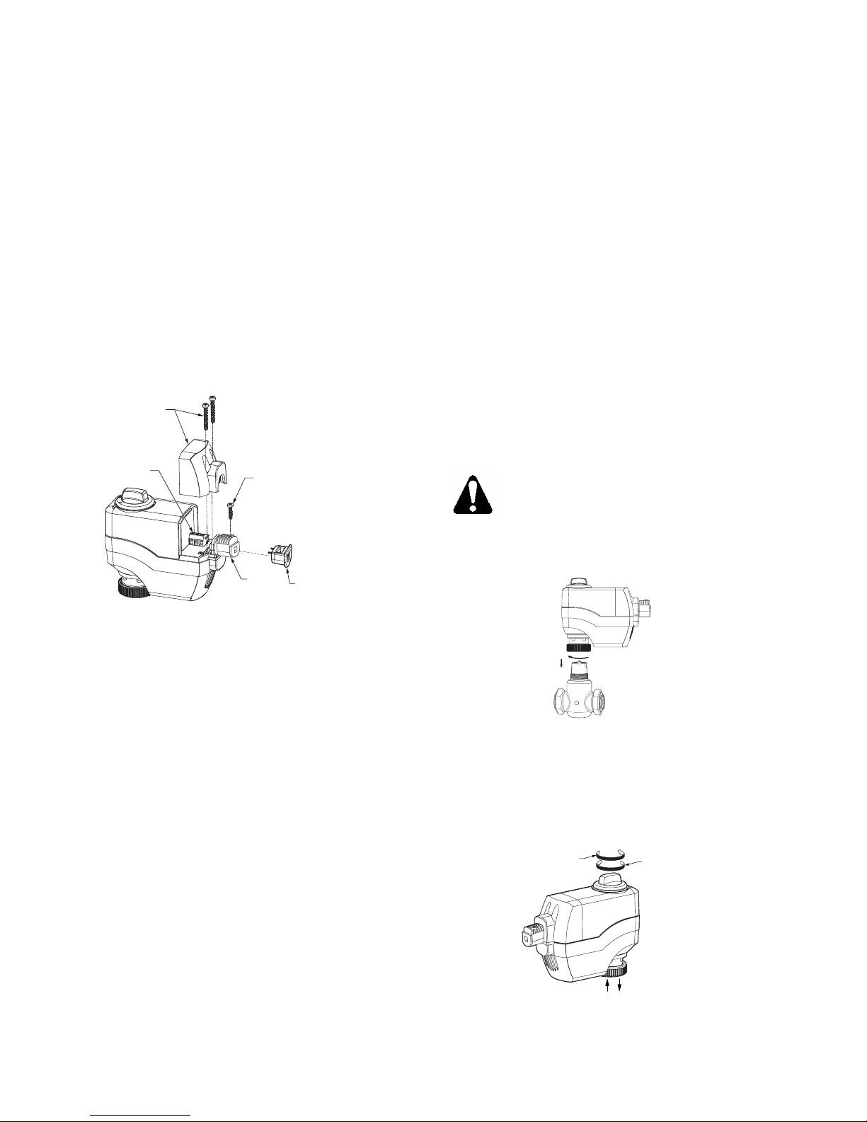
1. Remove the terminal cover (Figure 2) using a Phillips
head screwdriver,
2. Identify and disconnect wiring from the terminals.
3. Remove wiring retention screw.
4. Do one of the following:
•Remove plenum cable adapter and plenum
cable; or
•Remove flex conduit.
5. Loosen the actuator coupling on the valve (Figure 3,
reverse #2).
6. Remove the actuator from the valve.
EA1154R1
WIRING TERMINAL
WITH REMOVABLE
TERMINAL BLOCK
TERMINAL
COVER
AND SCREWS
FLEX
CONDUIT
ADAPTER
PLENUM CABLE
ADAPTER
(OPTIONAL USE)
WIRING
RETENTION
SCREW
Figure 2. SSC Actuator Components.
Mounting an Actuator on a Valve
1. If you are attaching the actuator to a new valve,
remove the protective plastic cap from the valve
stem.
2. Turn the manual position indicator on the top of the
actuator to the 0 position (Figure 10).
3. Using a Phillips head screwdriver, remove the
terminal cover (Figure 2).
4. Remove wiring retention screw.
5. Remove plenum cable adapter.
6. For plenum applications, complete wiring as follows:
a. Route cable through plenum cable adapter so
there is sufficient cable to complete wiring
terminations.
b. Insert plenum cable adapter into flex conduit
adapter and secure in place with wiring retention
screw.
NOTE: Insert wiring retention screw in hole farthest from
wiring terminals. (The hole nearest the wiring
terminals is to secure the terminal cover in
place.)
c. Continue with Step 8.
7. For 3/8-inch flex conduit applications, complete
wiring as follows:
a. Discard plenum cable adapter.
b. Insert flex conduit into flex conduit adapter and
secure in place with wiring retention screw.
NOTE: Insert wiring retention screw in hole
farthest from wiring terminals. (The
hole nearest the wiring terminals is
to secure the terminal cover in
place.)
c. Route wiring through flex conduit for wiring
terminations.
8. Connect wires to wiring terminals per the Wiring
section of this document.
9. Secure the terminal cover in place over the wiring
terminals (Figure 2) using a Phillips head
screwdriver,
10. Place the actuator on the valve and firmly hand-
tighten (Figure 3).
CAUTION:
Hand-tighten the actuator to the valve. The
use of tools to tighten the assembly together,
will cause damage.
The installation is complete.
EA1160R1
1
2
Figure 3. Coupling Actuator to Valve.
Manual Override
To position the actuator manually, use the manual override
knob in the center of the position indicator (Figure 4).
CLOCKWISE
EXTENDS
SHAFT
COUNTER
CLOCKWISE
RETRACTS
SHAFT
EA1161R1
A
B
AB
Figure 4. Manual Override.
Document No. 129-253
Installation Instructions
August 2, 2007
Siemens Building Technologies, Inc. Page 3 of 4
Calibration Stroke
The SSC Series writes its calibration stroke parameters to
nonvolatile memory on the first start-up of the actuator.
Successive start-ups bypass the calibration stroke unless
the memory is manually cleared. If installing the actuator
on a different valve (such as on a replacement valve),
manually clear the calibration stroke from memory as
follows:
1. Remove the terminal cover using a Phillips head
screwdriver.
2. Locate hole on the circuit board with the shorting
bars (Figure 5).
3. With power applied to the unit, insert and gently twist
a flat-blade screwdriver to electrically connect the
shorting bars. The SSC… then performs a new
calibration stroke.
4. Secure the terminal cover back in place.
EA1155R1
WIRING TERMINAL
WITH REMOVABLE
TERMINAL BLOCK
Shorting
Bars
TERMINAL
COVER
AND SCREWS
Figure 5. Manually Clearing Calibration Stroke from
SSC61U and SSC61.5U Nonvolatile Memory.
Wiring
•All wiring must conform to NEC and local codes
and regulations.
•Use earth ground isolating, step-down Class 2
transformers. Do not use autotransformers.
•Determine the supply transformer rating by
summing the total VA of all actuators used. The
maximum rating for a Class 2 step-down
transformer is 100 VA.
•Do not power more than 10 actuators with one
transformer.
NEUT
CONTROLLER ACTUATOR
EARTH GROUND
ISOLATING CLASS 2
TRANSFORMER FOR
24 Vac POWER
120 Vac
1
0
Y2
Y1
G
24
Vac
EA0795R1
Y2: Retracts actuator
shaft
Y1: Extends actuator shaft
G: System potential
Figure 6. SSC81U NSR Floating Control.
EA1235R1
NEUT
CONTROLLER
EARTH GROUND
ISOLATING CLASS 2
24 Vac TRANSFORMER
120 Vac
24 Vac
ACTUATOR
G
Y2
Y1
G0
1
0
0
G, G0: 24 Vac
operating voltage
Y2: Retracts actuator shaft
Y1: Extends actuator shaft
G: System potential
G0: System neutral
Figure 7. SSC81.5U Floating Control SR
Hot-Switch.
CAUTION:
Terminals must be properly wired for
correct function and full life of the actuator.
EA1234R1
NEUT
CONTROLLER
EARTH GROUND
ISOLATING CLASS 2
24 Vac TRANSFORMER
120 Vac
24 Vac
ACTUATOR
G
Y2
Y1
G0
1
0
0
G, G0: 24 Vac operating voltage
Y2: Retracts actuator shaft
Y1: Extends actuator shaft
G: System potential
G0: System neutral
Figure 8. SSC81.5U Floating Control SR Neutral
Switching Applications.
NOTE: For proper operation, it is recommended no
more than three actuators be assigned to any
single one control signal.
+
-
Y
G0
GR1
24
Vac
NEUT
ACTUATOR
EARTH GROUND
ISOLATING CLASS
2
TRANSFORMER FO
R
24Vac POWER
120Vac
ELECTRONIC
CONTROLLER
G, G0: 24 Vac operating voltage
Y: *0 to 10 Vdc control signal
G: System potential
G0: System neutral
R1: 500 ohm resistor
(optional for 0-20mA
operation)
Figure 9.
SSC61U, NSR and SC61.5U, SR,
0 to 10 Vdc Proportional Control Wiring Diagram.
*4 to 20 mA with optional
resistor
Document No. 129-253
Installation Instructions
August 2, 2007
Information in this publication is based on current specifications. The company reserves the right to make changes in specifications and
models as design improvements are introduced. Other product or company names mentioned herein may be the trademarks of their
respective owners. © 2007 Siemens Building Technologies, Inc.
Siemens Building Technologies, Inc.
1000 Deerfield Parkway
Buffalo Grove, IL 60089-4513
U.S.A.
Your feedback is important to us. If you have
comments about this document, please send
them to [email protected]
Document No. 129-253
Country of Origin: US
Page 4of 4
Start-up
Check the wiring and the position indicator (Figure 10).
Position
Indicator Output
Shaft
0 Retracted
1 Extended
NOTE:
"0" and "1" markings are
intended for reference only,
and not stroke
measurement.
0
1
EA1158R1
Figure 10. Position Indicator (Shown in 0 Position).
Troubleshooting
Check the wiring for the proper connections.
References
Technical Instructions Document No.
EA 599-15 Powermite 599 Series SSC
Electronic Valve Actuator 24 Vac
Proportional Control
155-313P25
EA 599-16 Powermite 599 Series SSC
Electronic Valve Actuator
3-position (Floating) Control
155-314P25
TB251, Powermite 599 Series, MT Series
Terminal Unit Valve and Actuator Assembly
Selection
155-306P25
Dimensions
2
(48)
4.4
(110.8)
3.5
(89.)
.85
(21.6)
4.5
(115.1) 5.5
(140.)
EA1159R1
0
1
Figure 11. SSC Actuator Dimensions in Inches (Millimeters).
Service Envelope
Minimum access space
recommended:
1. 8 inches (200 mm)
above the actuator.
2. 8 inches (200 mm)
beside the terminal
cover.

This manual suits for next models

3

Other Siemens Controllers manuals

Siemens RBC User manual

Siemens

Siemens RBC User manual

Siemens Ertec 400 User manual

Siemens

Siemens Ertec 400 User manual

Siemens SAS61.03U User manual

Siemens

Siemens SAS61.03U User manual

Siemens RDF870KN User manual

Siemens

Siemens RDF870KN User manual

Siemens SITRANS S7-300 User manual

Siemens

Siemens SITRANS S7-300 User manual

Siemens RVL479 User manual

Siemens

Siemens RVL479 User manual

Siemens SIMATIC S7 User guide

Siemens

Siemens SIMATIC S7 User guide

Siemens 3RA2220 User manual

Siemens

Siemens 3RA2220 User manual

Siemens WS 720 A User manual

Siemens

Siemens WS 720 A User manual

Siemens G2540 Series User manual

Siemens

Siemens G2540 Series User manual

Siemens 91-HF Manual

Siemens

Siemens 91-HF Manual

Siemens SIDOOR AT40 User guide

Siemens

Siemens SIDOOR AT40 User guide

Siemens SIMATIC ET 200SP User manual

Siemens

Siemens SIMATIC ET 200SP User manual

Siemens SIPLUS HCS3200 Administrator guide

Siemens

Siemens SIPLUS HCS3200 Administrator guide

Siemens ERTEC 200P-2 User manual

Siemens

Siemens ERTEC 200P-2 User manual

Siemens ECOFAST User manual

Siemens

Siemens ECOFAST User manual

Siemens SIMOTION C230-2 User manual

Siemens

Siemens SIMOTION C230-2 User manual

Siemens TUTORbit POL687 Service manual

Siemens

Siemens TUTORbit POL687 Service manual

Siemens SINAMICS S120 User manual

Siemens

Siemens SINAMICS S120 User manual

Siemens 5WG1 513-1AB11 User manual

Siemens

Siemens 5WG1 513-1AB11 User manual

Siemens 3RE4 User manual

Siemens

Siemens 3RE4 User manual

Siemens ACVATIX SAX319.03 User manual

Siemens

Siemens ACVATIX SAX319.03 User manual

Siemens SIRIUS 3RA2120 Series User manual

Siemens

Siemens SIRIUS 3RA2120 Series User manual

Siemens 7SR224 User manual

Siemens

Siemens 7SR224 User manual

Popular Controllers manuals by other brands

Allen-Bradley SLC 500 user manual

Allen-Bradley

Allen-Bradley SLC 500 user manual

Evco EVK004 manual

Evco

Evco EVK004 manual

Timeguard RTS113 Quick start instructions

Timeguard

Timeguard RTS113 Quick start instructions

Hanna Instruments HI 23 Series instruction manual

Hanna Instruments

Hanna Instruments HI 23 Series instruction manual

Fenwal 35-61 Series manual

Fenwal

Fenwal 35-61 Series manual

Dometic WAECO ASC G WI-FI KIT operating manual

Dometic

Dometic WAECO ASC G WI-FI KIT operating manual

ABB ACS 400 user guide

ABB

ABB ACS 400 user guide

RNA ESK 2001 operating instructions

RNA

RNA ESK 2001 operating instructions

Progres Agronic 7000 installation manual

Progres

Progres Agronic 7000 installation manual

LSI LSI53C1030 Technical manual

LSI

LSI LSI53C1030 Technical manual

Mect TPAC1008 03 Series user manual

Mect

Mect TPAC1008 03 Series user manual

ADEMCO 1007 manual

ADEMCO

ADEMCO 1007 manual

Kelly KLS14801-8080N user manual

Kelly

Kelly KLS14801-8080N user manual

Newport SMC100PP manual

Newport

Newport SMC100PP manual

LSIS XEC-DN32U user manual

LSIS

LSIS XEC-DN32U user manual

Johnson Controls FW-08 quick start guide

Johnson Controls

Johnson Controls FW-08 quick start guide

Bosch CLIMATE 5000 VRF RDCI Series Installation & user manual

Bosch

Bosch CLIMATE 5000 VRF RDCI Series Installation & user manual

Honeywell ComfortPoint Open CPO-VAV2A installation instructions

Honeywell

Honeywell ComfortPoint Open CPO-VAV2A installation instructions

manuals.online logo
manuals.online logoBrands
  • About & Mission
  • Contact us
  • Privacy Policy
  • Terms and Conditions

Copyright 2025 Manuals.Online. All Rights Reserved.