Installation Instructions
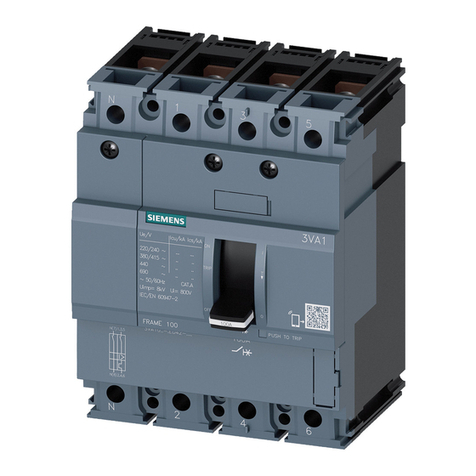
The following instructions are for the installation of Siemens strap kit S3VA55TD in a Distribution Switchboard or P5 Power
Panel. It is for use with a Siemens Type 3VA55 (MMAS, HMAS or CMAS) or Type 3VA65 (MMAE, HMAE or CMAE) breaker
as a Main or Branch device in an 800A application, or Type 3VA66 (MMNAE, HMNAE or CMNAE) breaker as a Main or Branch
device in a 1000A application. The parts provided in this kit connect these breakers to a 1-phase, 2 or 3-wire system or a
3-phase 3 or 4-wire system. This kit requires 8.75” of unit space. Breaker kit can be installed as shown or rotated 180°. (If
rotated, interchange A-phase and C-phase references in the assembly instructions.)
NOTE: The breakers and breaker lugs are NOT included in this kit and must be purchased separately.
11-B-1097-01 Rev. 00-3--2-
1. Lock off power supplying this equipment
before working on it.
5. Orient one of the Mounting Brackets (Item 1) as
shown and attach it to the Z-rail with two 1/4”-20
screws (Item 19).
3. This kit requires 8.75” of empty unit space.
To locate
the proper mounting position, measure from the top
deadfront support to the top of the empty unit space
filler on the deadfront. Transfer this dimension from
the deadfront support along the Z-rail and mark. This
will be
the unit space (as shown in Figure 3). After
marking the Z-rail, remove the deadfront.
4
.
If an existing branch module occupies the same
location chosen for this kit, remove all of its devices,
components and parts.
INSTALLING THE MOUNTING BRACKETS:
INSTALLING THE SIEMENS BREAKER:
8. Align the Barrier (Item 2) to the Mounting Brackets
(Item 1) as shown and loosely fasten with the four
1/4”-20 tall hex screws (Item 20).
INSTALLING THE BARRIER:
2. Remove the two gutter covers.
Figure 1
Figure 2
COVER
PLATES
GUTTER
COVERS
Z-RAIL
DEADFRONT
SUPPORTS
DEADFRONT
RAIL (Provision instructions on following page)
6. Repeat for the second Mounting Bracket.
7. Tighten the four screws
to the torque specified on the
rear of the deadfront or noted in the table on this page.
10. To install the
(A-phase) Short Strap (Item 3) and the
(C-phase) Long Strap (Item 5),
locate them as shown,
aligning the holes in the straps to the posts on the
barrier, and loosely attach them to the A and C-phase
bus (respectively) with the four appropriate 1/4”-20
screws from the Bus Hardware Kit (Item 17) each,
thru the straps and into the bus.
11. Tighten all the Barrier and Strap screws
to the torque
specified on the rear of the deadfront or noted in the table
on page 2.
PREPARING THE EQUIPMENT:
9. For three-phase installation ONLY:
(Skip to Step 10 for single-phase systems)
To install the (B-phase) Medium Strap (Item 4), locate
it as
shown, aligning the holes in the strap to the posts
on the barrier, and loosely attach it to the B-phase bus
with the four appropriate 1/4“-20 screws from the Bus
Hardware Kit (Item 17) thru the strap and
into the bus.
INSTALLING THE BREAKER STRAPS:
(Refer to Figures 1, 2 and 3)
(Refer to Figure 3)
(Refer to Figure 4)
(Refer to Figure 5)
12. Remove the breaker “OFF”-side shield cover and
nut keepers, per the breaker instructions.
13. Install lug kit (NOT INCLUDED) per lug installation
instructions. (Do NOT install lug covers at this time.)
14. Remove the breaker “ON”-side shield cover, and
clip off just enough mesh to clear the straps. (Leave
the nut keepers in place.)
(Refer to Figure 6)
15. Slide the breaker “ON”-side stabs under the bus
straps, aligning the holes, and loosely fasten with the
M10 SEMS Screws (Item 21).
16. Loosely secure the breaker “OFF”-side to the Barrier
(Item 2) using the pair of M6 x 80mm mounting
screws that came with the breaker.
( Breaker sold separately)
17. Tighten all the screws
to the following torque:
M10 screws: 275 lb-in M6 screws: 18 lb-in
19. Re-install the “OFF”-side and modified “ON”-side
shield covers by sliding them down over the proper
ends, inserting the shield cover screws and tightening
to 13 lb-in.
18. Insert and secure the cables to the lugs on the
“OFF”-side of the breaker, and tighten to the torque
noted in the lug instruction sheet, on the device or
specified on the rear of the deadfront.
INSTALLING THE COVER PLATE:
21. Install the Cover Plate (Item 6) by aligning the opening
over the breaker and loosely secure it to the deadfront
support rails with the four 1/4”-20 x 3/8” screws (Item 18).
(Refer to Figure 8)
22. Once all the covers are in place, tighten all the screws
to the torque specified on the rear of the deadfront or
noted in the table on page 2.
23. Follow the
instructions
provided with the
Handle Extension
Holder Assembly
(Item 9) to locate
and install it.
Z-RAIL
AØ BØ CØ
19
1
Figure 3
8.75”
UNIT
SPACE
1.87”
AØ BØ CØ
Figure 4 20
2
20. If this kit is installed in a panelboard, install the
Panelboard Neutral Lug Assembly (Item 10).
If this kit is installed in a switchboard,
install the
Switchboard Neutral Lug Assembly (Item 11).
INSTALLING THE NEUTRAL LUG:
24. Ensure that any bus or breaker hardware is
torqued as specified on the rear of the deadfront.
Then replace all the cover plates and gutter
covers. Finally, ensure any fillers are in place
BEFORE re-energizing the equipment.
COMPLETING THE INSTALLATION:
HANDLE EXTENSION:
AØ
BØ CØ
Figure 6
21
“ON”
side
“OFF”
side
“ON”-side
Shield Cover
M6 x 80mm
Nut
Keeper
“OFF”-side
Shield Cover
Mesh
Shield
Screws
Figure 7b
11
Figure 7a 10
(Refer to Figures 7a and 7b)
18
Figure 8
6
HANDLE
EXTENSION
HANDLE
HOLDER
3VA BREAKER
ON / OFF
HANDLE
9
Figure 9
(Refer to Figure 9)
AØ
BØ
CØ
Figure 5
17
3
4
5
THIS KIT CONTAINS THE FOLLOWING ITEMS:
* This sub-kit of parts is packaged in a bag labeled “Standard Bus Hardware
Kit”. It includes an instruction card and 18 fasteners (of three different
lengths). Select fasteners per the instruction card and discard the rest.
ITEM
DESCRIPTION
QTY
1
2
3
4
5
6
7
8
9
10
Card Holder
#10-32 Thread-forming Screw
Handle Extension Holder Assembly
Medium Strap
Short Strap
Barrier
Circuit ID Card 1
1
1
1
1
1
1
1
11
12
Long Strap
Provision Filler
2
1
13
14
Panelboard Neutral Branch Lug Assy. 4
15
16 #10 Locknut
#10-24 x 5/8” Round-head Screw
1
2
Provision Strap Barrier
Switchboard Neutral Branch Lug Assy. 4
Mounting Bracket 2
Cover Plate 1
TORQUE
N/A
N/A
N/A
N/A
N/A
N/A
N/A
N/A
N/A
N/A
N/A
20 lb-in
30 lb-in
N/A
N/A
N/A
1/4”-20 x 1/2” Hex Head Washer Screw
1
4
17
1/4”-20 x 3/8” Hex Head Washer Screw
4
18
19
20
21 M10 SEMS Screw **
1/4”-20 x 1/2” Tall Hex Washer Screw
4
6
Bus Hardware Kit, Strap to Section * 72 lb-in
40 lb-in
72 lb-in
72 lb-in
275 lb-in
** Breakers ship with six M10 Screws; those should be discarded.
Instead, use the six M10 SEMS Screws included with this kit.
Hazardous voltage.
Will cause death or
serious injury.
Keep out.
Qualified personnel only.
Disconnect and lock off all
power before working on
this equipment.
DANGER
!
