Installation Instructions
The following instructions are for the installation of Siemens Type GB2 breakers (NGB2, HGB2 or LGB2) as
branch devices in a Switchboard or Type P4 or Type P5 Panelboard. The parts provided in this kit connect
Type GB2 breakers to 3-phase/3-wire or 3-phase/4-wire systems ONLY. Kit SGB2 is for shallow (P4)
installations; kit SGB2D is for deep (P5 and Switchboard Distribution Section) installations. This kit requires
3-3/4” of unit space. NOTE: The breakers are NOT included in this kit and must be purchased separately.
12-A-1031-01 Rev. 00
-3--2-
DANGER
Hazardous voltage.
Will cause death or
serious injury.
Keep out.
Qualified personnel only.
Disconnect and lock off all
power before working on
this equipment.
1. Lock off power supplying this equipment
before working on it.
7.
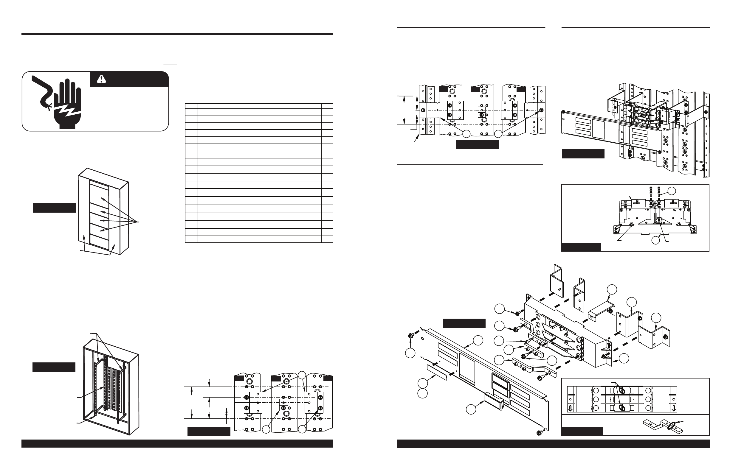
Reference Figure 4
Locate a 0.228” diameter hole in the left Z-rail
1.88” below the top of the empty unit space
selected. Insert a 1/4”-20 x 3/8” screw (Item 14)
through the barrier support bracket (Item 5)
mounting hole and into the selected hole in the
Z-rail (orienting the bracket as shown). Repeat
this for the second mounting bracket. Tighten
these two screws (Item 14).
3. Refer to Figure 2
To mount a Siemens Type GB2 circuit breaker,
3-3/4” of empty unit space is required. To locate
the proper mounting position, measure from the
top deadfront support to the intended location of
the empty unit space (filler) on the deadfront.
Transfer this dimension from the deadfront
support along the Z-rail and mark. This will be
the unit space (as shown in Figures 3 & 4). After
marking the Z-rail, remove the deadfront rails.
4
.
If an existing branch module occupies the same
location chosen for this kit, remove all of its
devices, components and parts.
INSTALLING THE RUNBACKS
6. Refer to Figure 3
Locate (2) 0.228” diameter holes in the A-phase
bus 1.25” down from the top of the 3.75” empty
unit space selected. Insert (2) 1/4”-20 screws (see
mounting hardware kit instructions located in Item
11
for the proper length) through the two mounting
holes in the A/C runback (Item 1) and into the (2)
selected holes in the A-phase bus (orienting the
A/C strap as shown) and tighten. Repeat this step
to mount the second runback to the C-phase bus.
Insert one 1/4”-20 screw (Item 11) through the
mounting hole in the B-phase runback (Item 3) and
into the proper 0.228” hole located in the B-phase
bus, 1.25” up from the bottom of the 3.75” empty
unit space (orienting the B-phase runback as shown)
and tighten. Torque all hardware as specified on
the rear of the deadfront.
INSTALLING THE MOUNTING BRACKETS
9. Reference Figure 6
Align the bottom of the Type GB2 Breaker with the
top of the barrier. Slide the breaker along until the
notch on the bottom of the breaker fully engages
the edge of the barrier (as shown in Figure 6a).
Once fully engaged, use #10-24 x 1/2” screws
(Item 13) to secure the breaker tabs to the properly
aligned straps. Torque all hardware as specified
on the rear of the deadfront.
INSTALLING THE TYPE GB2 BREAKER
8. Reference Figure 5
Set the top barrier (Item 6) over the two barrier
support brackets (Item 5) such that the barrier
mounting holes align with the holes on the brackets.
Insert a #10-24 x 3/8” screw (Item 12) on each
side of the barrier and tighten. To install the
B-phase strap (Item 4), locate it in the center
opening such that the center hole lines up with
the mounting hole on the B-phase runback. Drive
a 1/4“-20 x 5/8” screw (Item 15) thru the strap and
into the runback and tighten. For the A & C-phase
straps (Item 2) take one and angle the mounting
side under the barrier such that the strap
mounting hole aligns with the appropriate hole in
the A-phase runback and the center hole of the
strap sits on the barrier locating pin (Figure 5a).
Drive a 1/4”-20 x 5/8” screw (Item 15) through the
strap and into the runback and tighten. Repeat
this for the C-phase strap as shown. Torque all
hardware as specified on the rear of the deadfront.
INSTALLING THE BARRIER & STRAPS
Figure 1
Figure 4
CENTER
HOLE
LOCATING PINS
Figure 5a
GB2
TOP
BARRIER
A/C
PHASE
STRAP
2. Refer to Figure 1
Remove the gutter covers and cover plates.
Figure 2
5. Open the shipping box and inspect the contents.
Figure 3
Figure 5
Figure 6a
GB2
BREAKER
NOTCH
ENGAGEMENT
6GB2
BREAKER
LINE STAB
GB2
BREAKER
BASE NOTCH
13
GB2
BREAKER
COVER
PLATES
GUTTER
COVERS
(INLINE)
3.75”
UNIT
SPACE
2.50”
1.25”
1.25”
AØ BØ CØ
1
311
Z-RAIL
3.75”
UNIT
SPACE
AØ
1.88”
1.25”
BØ CØ
5
14
(SHALLOW KIT
REFERENCE)
3
1
5
6
2
4
13
15
12
8
9
10
14
7
Figure 6
(DEEP KIT
REFERENCE)
WARNING: Do NOT use with NGB, LGB or HGB breakers. ONLY use with NGB2, LGB2 or HGB2 breakers.
WARNING: Do NOT use with NGB, LGB or HGB breakers. ONLY use with NGB2, LGB2 or HGB2 breakers.
THIS KIT CONTAINS THE FOLLOWING ITEMS:
*
Kit contains shorter units for shallow applications (SGB2)
or taller units for deeper applications (SGB2D).
**
Application dictates amount of these components used.
*** SGB2D only
ITEM
DESCRIPTION
QTY
1
2
3
4
5
6
7
8
9
10
Circuit ID Card
#10-24 x 1/2” Socket Head Cap Screw
Card Holder
B-phase Strap
B-phase Runback *
A/C-phase Strap
3-3/4” Cover Plate 1
2
1
1
6
2
6
6
11
12
GB2 Barrier Support Bracket *
1/4”-20 x 5/8” Hex Head Washer Screw ** 5
2
13
14
Blank Filler ** 6
15
16 #8-32 x 5/8” Hex Head Washer Screw
1/4”-20 x 3/8” Hex Head Washer Screw 4
2
#10-24 x 3/8” Hex Head Washer Screw
Bus Hardware Kit, 1/8” Strap to Section ** 1
A/C-phase Runback * 2
GB2 Top Barrier 1
Branch Neutral Connector *** 1
17
18 Branch Neutral Terminal Strip 1
15
Z-RAIL
DEADFRONT
SUPPORTS
DEADFRONT
RAIL


