manuals.online logo
Brands
  1. Home
  2. •
  3. Brands
  4. •
  5. Siemens
  6. •
  7. Media Converter
  8. •
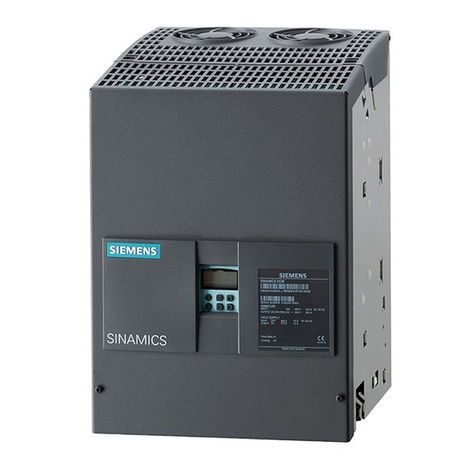
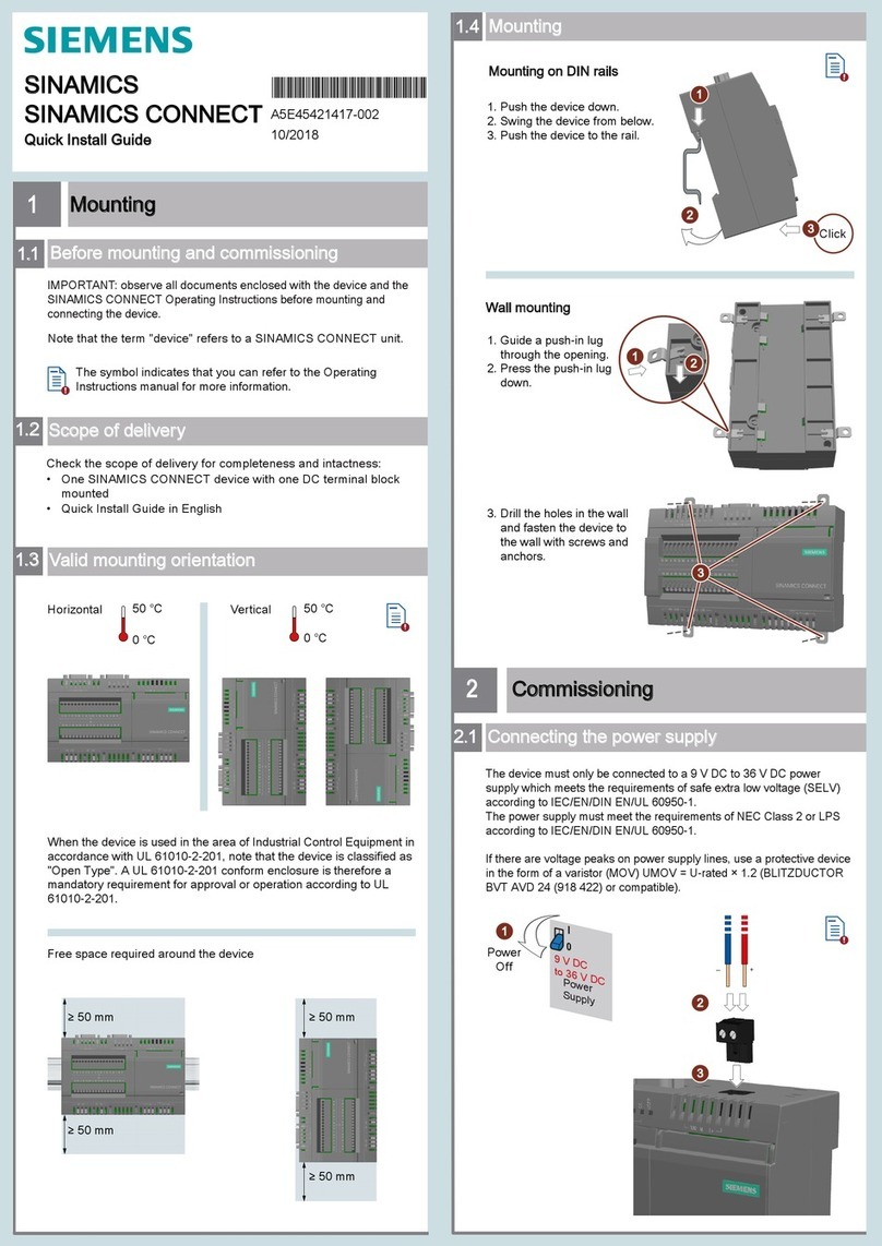
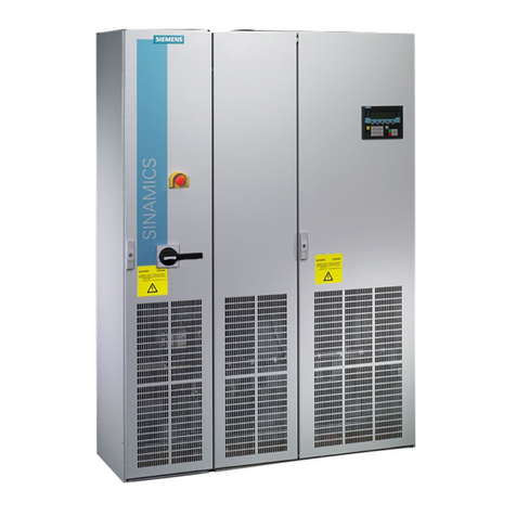
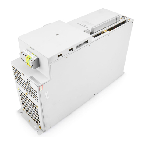
  9. Siemens SINAMICS DCM User manual

Siemens SINAMICS DCM User manual

www.barghmaher.org
ac.maher.co.ir
SINAMICS
SINAMICS DCM DC Converter
Operating Instructions
Software version 1.4.1
02.2015
A5E34763375/RS
-AA/001
Information
1
Type spectrum, ordering
information
2
Description
3
Technical data
4
Transportation, unpacking,
installation
5
Connecting
6
Additional system
components
7
Commissioning
8
Operation
9
Descriptions of functions
10
Maintenance
11
Applications
12
Appendix A
A
Appendix B
B
www.barghmaher.org
ac.maher.co.ir
Siemens AG
Division Process Industries and Drives
Postfach 48 48
90026 NÜRNBERG
GERMANY
Order number: 6RX1800-0AD76
Ⓟ
05/2015 Subject to change
Copyright © Siemens AG 2009 - 2015.
All rights reserved
Legal information
Warning notice system
This manual contains notices you have to observe in order to ensure your personal safety, as well as to prevent
damage to property. The notices referring to your personal safety are highlighted in the manual by a safety alert
symbol, notices referring only to property damage have no safety alert symbol. These notices shown below are
graded according to the degree of danger.
DANGER
indicates that death or severe personal injury will result if proper precautions are not taken.
WARNING
indicates that death or severe personal injury
may
result if proper precautions are not taken.
CAUTION
indicates that minor personal injury can result if proper precautions are not taken.
NOTICE
indicates that property damage can result if proper precautions are not taken.
If more than one degree of danger is present, the warning notice representing the highest degree of danger will
be used. A notice warning of injury to persons with a safety alert symbol may also include a warning relating to
property damage.
Qualified Personnel
The product/system described in this documentation may be operated only by
personnel qualified
for the specific
task in accordance with the relevant documentation, in particular its warning notices and safety instructions.
Qualified personnel are those who, based on their training and experience, are capable of identifying risks and
avoiding potential hazards when working with these products/systems.
Proper use of Siemens products
Note the following:
WARNING
Siemens products may only be used for the applications described in the catalog and in the relevant technical
documentation. If products and components from other manufacturers are used, these must be recommended
or approved by Siemens. Proper transport, storage, installation, assembly, commissioning, operation and
maintenance are required to ensure that the products operate safely and without any problems. The permissible
ambient conditions must be complied with. The information in the relevant documentation must be observed.
Trademarks
All names identified by ® are registered trademarks of Siemens AG. The remaining trademarks in this publication
may be trademarks whose use by third parties for their own purposes could violate the rights of the owner.
Disclaimer of Liability
We have reviewed the contents of this publication to ensure consistency with the hardware and software
described. Since variance cannot be precluded entirely, we cannot guarantee full consistency. However, the
information in this publication is reviewed regularly and any necessary corrections are included in subsequent
editions.
www.barghmaher.org
ac.maher.co.ir
SINAMICS DCM DC Converter
Operating Instructions, 02.2015, A5E34763375/RS-AA/001 5
Preface
Note
Information on connecting the device
The inside front cover of the SINAMICS DC MASTER Operating Instructions contains a
summary of the key information required for connecting the device.
Product name
The SINAMICS DCM documentation uses the following product names:
●SINAMICS DCM
●SINAMICS DC MASTER
Device software version
When these operating instructions went to print, SINAMICS DCM devices were being
supplied from the factory with the software release specified on Page 3.
However, these Operating Instructions can, in principle, also apply to other software
versions.
●
Older software versions:
It is possible that not all of the functions described here may be available.
●
Newer software versions:
It is possible that the SINAMICS DCM may feature additional functions that are not
described in these Operating Instructions. Do not change any parameters that you cannot
find in the List Manual from their factory setting, and do not give parameters any values
that are not specified in the List Manual.
The software release is displayed using r50060[6].
Example:
01010203 displayed on the BOP20 means 01.01.02.03 → Version 1.1, Service Pack 2, Hotfix
3
When required, you can obtain the current software from your local Siemens sales office.
Download of the current software version for registered users
(https://support.industry.siemens.com/cs/ww/en/view/44029688)
www.barghmaher.org
ac.maher.co.ir
Preface
SINAMICS DCM DC Converter
6Operating Instructions, 02.2015, A5E34763375/RS-AA/001
Note
Hardware/software compatibility
The hardware version of the Control Unit (CUD) must be taken into account when updating
the device software. See the table below.
The hardware version can be read from the label on the right
-hand side of the CUD.
CUD (print on label)
Executable software versions
C98043-A7100-
L1
-...
C98043-A7100-
L2
-...
C98043-A7100-
L100
-...
C98043-A7100-L200-...
1.1, 1.2, 1.3
C98043-A7100-
L3
-...
C98043-A7100-
L4
-...
C98043-A7100-
L103
-...
C98043-A7100-L204-...
All versions
A5E...
All versions
SINAMICS DCM documentation available
SINAMICS DCM DC Converters Operating Instructions
contains all information on
ordering, installation, connecting, commissioning, maintaining, description of functions,
and service
SINAMICS DCM Control Modules Operating Instructions
contains all information on
ordering, installation, connecting, commissioning, maintaining, description of functions,
and service
SINAMICS DCM List Manual (for DC converters and control modules)
Contains
parameter list, function diagrams, list of faults and alarms
SINAMICS free function blocks, function description
Includes a general description, list of parameters, the function block diagrams as well as
the list of faults and alarms.
SINAMICS DCM DVD documentation
Includes
All the
manuals listed above, in all of the available languages
Function diagrams in VISIO® format
Application notes
Spare parts list
www.barghmaher.org
ac.maher.co.ir
Preface
SINAMICS DCM DC Converter
Operating Instructions, 02.2015, A5E34763375/RS-AA/001 7
Manuals and application notes on the Internet
The manuals and application documents are also available in the Internet:
Manuals (https://support.industry.siemens.com/cs/ww/en/ps/13298/man)
The list of general conditions available there include current supplements to the manuals.
The notes included in the general condition lists have a higher priority than the statements
made in the manuals.
FAQ in the Internet
FAQ (http://support.automation.siemens.com/WW/view/en/38157755/133000)
Service
You can find information on our services and regional contact persons in the Internet -
(https://support.industry.siemens.com/sc/ww/en/sc)
Technical Support
Our technical support can provide you with technical assistance for products, systems, and
solutions:
Service (https://support.industry.siemens.com/sc/ww/en/sc)
Central hotlines for SINAMICS DCM technical support
European and African time
zone
Service Request
(https://support.industry.siemens.com/My/ww/en/requests#cr
eateRequest)
America time zone
24-hour hotline: +1 800 333 7421
Phone: +1 423 262 2960
Fax: +1 423 262 2200
email (mailto:[email protected])
8:00 to 17:00
Eastern Standard Time
Asia/Australia time zone
Phone: +86 1064 757575
Fax: +86 1064 747474
email (mailto:[email protected])
7:30 to 17:30
Beijing local time
www.barghmaher.org
ac.maher.co.ir
Preface
SINAMICS DCM DC Converter
8Operating Instructions, 02.2015, A5E34763375/RS-AA/001
Spare parts
You can find information on spare parts
●In catalog D23.1
●On the SINAMICS DCM documentation DVD
(to reorder please quote article number 6RX1800-0AD64)
●Via the electronic spare parts catalog Spares On Web, after entering the serial number
and article number of your SINAMICS DCM in the Internet (registration required).
Spares on Web (http://www.siemens.com/sow)
Remark for users of Internet Explorer 10:
This website may only be correctly displayed when the browser is switched to
compatibility mode (activate the appropriate button in the input line or use the menu
Options → Settings of the compatibility view).
Availability of spare parts (http://www.siemens.com/sos)
Further Internet links
Generic station description file (GSD) for
PROFIBUS (https://support.industry.siemens.com/cs/ww/en/view/98206128)
PROFINET (https://support.industry.siemens.com/cs/ww/en/view/98206128)
www.barghmaher.org
ac.maher.co.ir
SINAMICS DCM DC Converter
Operating Instructions, 02.2015, A5E34763375/RS-AA/001 9
Table of contents
Preface ................................................................................................................................................... 5
1 Information............................................................................................................................................ 19
1.1 Warning information................................................................................................................19
1.2 ESD-sensitive components.....................................................................................................22
2 Type spectrum, ordering information ..................................................................................................... 23
2.1 Device article numbers ...........................................................................................................24
2.2 Key for the device article numbers .........................................................................................26
2.3 Rating plates, packaging label................................................................................................28
2.4 Ordering information for options and accessories ..................................................................30
2.5 Accessories.............................................................................................................................35
2.5.1 SIMOREG DC-MASTER Converter Commutation Protector (CCP) ......................................35
2.5.2 Mounting kit to increase the degree of protection to IP20 ......................................................36
3 Description............................................................................................................................................ 37
4 Technical data ...................................................................................................................................... 41
4.1 Load types ..............................................................................................................................42
4.2 Environmental requirements...................................................................................................47
4.3 Unit data..................................................................................................................................49
4.4 Derating ..................................................................................................................................74
5 Transportation, unpacking, installation .................................................................................................. 77
5.1 Transportation, unpacking ......................................................................................................77
5.2 Installation...............................................................................................................................78
5.2.1 Dimension drawings................................................................................................................81
5.2.2 Installing options and accessories ..........................................................................................90
5.2.2.1 AOP30 operator panel ............................................................................................................90
5.2.2.2 Installing a second CUD .........................................................................................................90
6 Connecting ........................................................................................................................................... 93
6.1 Instructions for EMC-compliant drive installation....................................................................95
6.1.1 Basic information about EMC .................................................................................................95
6.1.2 EMC-compliant drive installation (installation instructions).....................................................98
6.1.3 Arranging components for converter units............................................................................105
6.1.4 RFI suppression filter ............................................................................................................106
6.1.5 Information on line-side harmonics produced by converter units in a fully-controlled
two-pulse bridge circuit configuration (B6C and (B6)A(B6)C) ..............................................107
6.1.6 Data on the line-side harmonics from converter units in a fully-controlled AC bridge
circuit B2C.............................................................................................................................109
6.2 Cable routing into the unit.....................................................................................................110
www.barghmaher.org
ac.maher.co.ir
Table of contents
SINAMICS DCM DC Converter
10 Operating Instructions, 02.2015, A5E34763375/RS-AA/001
6.3 Block diagram with connection suggestion.......................................................................... 114
6.4 Power connections............................................................................................................... 122
6.5 Field supply .......................................................................................................................... 143
6.6 Line reactors ........................................................................................................................ 146
6.7 Fuses ................................................................................................................................... 150
6.7.1 Fuses for the exciter circuit .................................................................................................. 150
6.7.2 Fuses for the armature circuit .............................................................................................. 150
6.7.3 Fuses in the Power Interface ............................................................................................... 156
6.8 Arrangement of terminals and connectors........................................................................... 157
6.9 Assignment of terminals and connectors............................................................................. 168
6.9.1 Power unit ............................................................................................................................ 169
6.9.2 Exciter circuit........................................................................................................................ 171
6.9.3 Electronics power supply ..................................................................................................... 172
6.9.4 Fan ....................................................................................................................................... 173
6.9.5 Open-loop and closed-loop control section ......................................................................... 174
6.9.6 Assignment of the RS485 cable to the AOP30.................................................................... 182
6.10 Installation notes for installation according to UL 508C....................................................... 187
7 Additional system components.............................................................................................................189
7.1 Option Board: Communication Board Ethernet CBE20 ....................................................... 190
7.1.1 Description ........................................................................................................................... 190
7.1.2 Safety instructions................................................................................................................ 190
7.1.3 Interface description............................................................................................................. 191
7.1.3.1 Overview .............................................................................................................................. 191
7.1.3.2 X1400 Ethernet interface ..................................................................................................... 191
7.1.4 Meaning of the LEDs ........................................................................................................... 192
7.1.5 Installation ............................................................................................................................ 194
7.1.6 Technical data...................................................................................................................... 194
7.2 Sensor Module Cabinet-Mounted SMC30 ........................................................................... 195
7.2.1 Description ........................................................................................................................... 195
7.2.2 Safety instructions................................................................................................................ 196
7.2.3 Interface description............................................................................................................. 199
7.2.3.1 Overview .............................................................................................................................. 199
7.2.3.2 X500 DRIVE-CLiQ interface ................................................................................................ 200
7.2.3.3 X520 encoder system interface ........................................................................................... 200
7.2.3.4 X521/X531 alternative encoder system interface ................................................................ 201
7.2.3.5 X524 electronic power supply .............................................................................................. 203
7.2.4Connection examples .......................................................................................................... 203
7.2.5 Meaning of the LEDs ........................................................................................................... 206
7.2.6 Dimension drawing .............................................................................................................. 207
7.2.7 Installation ............................................................................................................................ 208
7.2.8 Protective conductor connection and shield support ........................................................... 209
7.2.9 Technical data...................................................................................................................... 210
7.3 Terminal Module TM15 ........................................................................................................ 214
7.3.1 Description ........................................................................................................................... 214
7.3.2 Safety instructions................................................................................................................ 214
7.3.3 Interface description............................................................................................................. 215
7.3.3.1 Overview .............................................................................................................................. 215
www.barghmaher.org
ac.maher.co.ir
Table of contents
SINAMICS DCM DC Converter
Operating Instructions, 02.2015, A5E34763375/RS-AA/001 11
7.3.3.2 X500 and X501 DRIVE-CLiQ interface.................................................................................216
7.3.3.3 X524 electronic power supply...............................................................................................217
7.3.3.4 X520 digital inputs/outputs....................................................................................................217
7.3.3.5 X521 digital inputs/outputs....................................................................................................218
7.3.3.6 X522 digital inputs/outputs....................................................................................................218
7.3.4 Connection example .............................................................................................................219
7.3.5 Meaning of the LEDs on the Terminal Module TM15 ...........................................................220
7.3.6 Dimension drawing ...............................................................................................................221
7.3.7 Installation.............................................................................................................................222
7.3.8 Protective conductor connection and shield support ............................................................223
7.3.9 Connector coding..................................................................................................................224
7.3.10 Technical data.......................................................................................................................225
7.4 Terminal Module TM31.........................................................................................................227
7.4.1 Description ............................................................................................................................227
7.4.2 Safety instructions.................................................................................................................227
7.4.3 Interface description..............................................................................................................229
7.4.3.1 Overview ...............................................................................................................................229
7.4.3.2 X500/X501 DRIVE-CLiQ interfaces ......................................................................................230
7.4.3.3 X520, X530 digital inputs ......................................................................................................231
7.4.3.4 X521 analog inputs ...............................................................................................................232
7.4.3.5 Analog inputs current/voltage switch ....................................................................................233
7.4.3.6 X522 analog outputs/temperature sensor.............................................................................233
7.4.3.7 X524 electronic power supply...............................................................................................234
7.4.3.8 X540 auxiliary voltage for the digital inputs ..........................................................................234
7.4.3.9 X541 bidirectional digital inputs/outputs ...............................................................................235
7.4.3.10 X542 relay outputs ................................................................................................................236
7.4.4 Connection example .............................................................................................................237
7.4.5 Meanings of the LEDs on the Terminal Module TM31 .........................................................238
7.4.6 Dimension drawing ...............................................................................................................239
7.4.7 Installation.............................................................................................................................240
7.4.8 Protective conductor connection and shield support ............................................................241
7.4.9 Connector coding..................................................................................................................242
7.4.10 Technical data.......................................................................................................................243
7.5 Terminal Module TM150.......................................................................................................244
7.5.1 Description ............................................................................................................................
244
7.5.2Safety instructions.................................................................................................................244
7.5.3 Interface description..............................................................................................................246
7.5.3.1 Overview ...............................................................................................................................246
7.5.3.2 X500 and X501 DRIVE-CLiQ interfaces ...............................................................................247
7.5.3.3 X524 Electronics power supply.............................................................................................248
7.5.3.4 X531-X536 temperature sensor inputs .................................................................................248
7.5.4 Connection examples ...........................................................................................................250
7.5.5 Meaning of the LEDs on the Terminal Module TM150 .........................................................252
7.5.6 Dimension drawing ...............................................................................................................253
7.5.7 Installation.............................................................................................................................254
7.5.8 Protective conductor connection and shield support ............................................................255
7.5.9 Technical data.......................................................................................................................256
8 Commissioning ................................................................................................................................... 257
8.1 Switching on..........................................................................................................................259
8.2 Commissioning using the BOP20 operator panel.................................................................260
www.barghmaher.org
ac.maher.co.ir
Table of contents
SINAMICS DCM DC Converter
12 Operating Instructions, 02.2015, A5E34763375/RS-AA/001
8.2.1 Preconditions ....................................................................................................................... 260
8.2.2 Commissioning steps........................................................................................................... 260
8.3 Commissioning using the AOP30 operator panel................................................................ 267
8.3.1 First commissioning ............................................................................................................. 267
8.3.1.1 First power-up ...................................................................................................................... 267
8.3.1.2 Full drive commissioning...................................................................................................... 268
8.3.2 Status after commissioning.................................................................................................. 272
8.3.3 Resetting parameters to factory settings ............................................................................. 272
8.4 Commissioning with the STARTER commissioning tool ..................................................... 273
8.4.1 STARTER commissioning tool............................................................................................. 273
8.4.1.1 Installing the STARTER commissioning tool ....................................................................... 273
8.4.1.2 Layout of the STARTER user interface ............................................................................... 274
8.4.2 Procedure for commissioning with STARTER ..................................................................... 275
8.4.2.1 Creating the project.............................................................................................................. 275
8.4.2.2 Configuring a drive unit ........................................................................................................ 282
8.4.2.3 Starting the drive project ...................................................................................................... 294
8.4.2.4 Connection through a serial interface .................................................................................. 298
8.5 Activating function modules ................................................................................................. 301
8.5.1 Activating offline with STARTER.......................................................................................... 302
8.5.2 Activating online through parameters .................................................................................. 303
8.6 Commissioning optional additional modules........................................................................ 305
8.6.1 Terminal Modules (TM31, TM15, TM150) ........................................................................... 305
8.6.1.1 Commissioning with STARTER ........................................................................................... 305
8.6.1.2 Commissioning via parameter assignment.......................................................................... 307
8.6.2 Encoder evaluation (SMC30)............................................................................................... 308
8.6.2.1 Add/commissioning (with STARTER) .................................................................................. 308
8.6.2.2 Remove (with STARTER) .................................................................................................... 311
8.6.3 PROFINET module (CBE20) ............................................................................................... 311
8.6.3.1 Adding online into the drive.................................................................................................. 311
8.6.3.2 Adding offline in STARTER.................................................................................................. 312
8.6.3.3 Deleting from the drive online .............................................................................................. 312
8.6.3.4 Deleting offline with STARTER ............................................................................................ 312
8.7 Drive optimization................................................................................................................. 313
8.8 Manual optimization ............................................................................................................. 319
8.8.1 Optimization of closed-loop armature current control .......................................................... 320
8.8.2Optimization of closed-loop field-current control.................................................................. 322
8.8.3 Optimizing the speed controller ........................................................................................... 323
9 Operation.............................................................................................................................................325
9.1 Basic information.................................................................................................................. 325
9.1.1 Parameter ............................................................................................................................ 325
9.1.2 Data sets .............................................................................................................................. 328
9.1.2.1 Function diagrams and parameters ..................................................................................... 331
9.1.2.2 Using data sets .................................................................................................................... 331
9.1.3 Drive objects ........................................................................................................................ 332
9.1.4 Memory card functions......................................................................................................... 334
9.1.5 BICO technology: Interconnecting signals........................................................................... 339
9.1.5.1 Binectors, connectors .......................................................................................................... 340
9.1.5.2 Interconnecting signals using BICO technology .................................................................. 340
www.barghmaher.org
ac.maher.co.ir
Table of contents
SINAMICS DCM DC Converter
Operating Instructions, 02.2015, A5E34763375/RS-AA/001 13
9.1.5.3 Internal encoding of the binector/connector output parameters ...........................................342
9.1.5.4 Example: Interconnecting digital signals...............................................................................342
9.1.5.5 Information on BICO technology...........................................................................................342
9.2 Parameterizing using the BOP20 (Basic Operator Panel 20)...............................................344
9.2.1 General information about the BOP20..................................................................................344
9.2.2 Displays and using the BOP20 .............................................................................................347
9.2.3 Displaying faults and alarms.................................................................................................352
9.2.4 Controlling the drive using the BOP20..................................................................................353
9.3 Controlling via the AOP30 operator panel ............................................................................354
9.3.1 Overview and menu structure...............................................................................................355
9.3.2 Menu: Operation screen .......................................................................................................357
9.3.3 Parameterization menu.........................................................................................................358
9.3.4 Menu: Fault/alarm memory ...................................................................................................359
9.3.5 Menu: Commissioning/Service .............................................................................................360
9.3.5.1 Drive commissioning.............................................................................................................360
9.3.5.2 Device commissioning ..........................................................................................................361
9.3.5.3 AOP settings .........................................................................................................................361
9.3.5.4 Lists of signals for the operation screen ...............................................................................362
9.3.5.5 AOP30 diagnostics ...............................................................................................................365
9.3.6 Sprachauswahl/Language selection .....................................................................................366
9.3.7 Operation via the operator panel (LOCAL mode).................................................................367
9.3.7.1 LOCAL/REMOTE key ...........................................................................................................367
9.3.7.2 ON key/OFF key ...................................................................................................................368
9.3.7.3 CCW/CW changeover...........................................................................................................368
9.3.7.4 Jogging .................................................................................................................................368
9.3.7.5 Increase setpoint/Decrease setpoint ....................................................................................369
9.3.7.6 AOP setpoint.........................................................................................................................369
9.3.7.7 Inhibiting AOP LOCAL mode ................................................................................................370
9.3.7.8 Acknowledging errors via the AOP .......................................................................................370
9.3.7.9 Timeout monitoring ...............................................................................................................370
9.3.7.10 Operator inhibit lock/Parameters disable..............................................................................371
9.3.8 Faults and alarms .................................................................................................................372
9.3.9 Saving the parameters permanently.....................................................................................374
9.3.10 Parameterization errors ........................................................................................................374
9.3.11 Assigning parameters to make AOP30 time-of-day master .................................................375
10 Descriptions of functions ..................................................................................................................... 377
10.1 Inputs/Outputs.......................................................................................................................377
10.1.1 Overview of inputs/outputs ...................................................................................................377
10.1.2 Digital inputs/outputs.............................................................................................................377
10.1.3 Analog inputs ........................................................................................................................378
10.1.4 Analog outputs ......................................................................................................................379
10.2 Communication, IT security ..................................................................................................380
10.3 Communication according to PROFIdrive ............................................................................381
10.3.1 Application classes ...............................................................................................................383
10.3.2 Cyclic communication ...........................................................................................................385
10.3.2.1 Telegrams and process data ................................................................................................385
10.3.2.2 Description of control words and setpoints...........................................................................388
10.3.2.3 Description of status words and actual values .....................................................................393
10.3.2.4 Control and status words for encoders .................................................................................399
www.barghmaher.org
ac.maher.co.ir
Table of contents
SINAMICS DCM DC Converter
14 Operating Instructions, 02.2015, A5E34763375/RS-AA/001
10.3.2.5 Extended encoder evaluation .............................................................................................. 408
10.3.2.6 Central control and status words ......................................................................................... 408
10.3.2.7 Diagnostics channels for cyclic communication................................................................... 411
10.3.3 Parallel operation of communication interfaces ................................................................... 412
10.3.4 Acyclic communication......................................................................................................... 415
10.3.4.1 General information about acyclic communication .............................................................. 415
10.3.4.2 Structure of orders and responses....................................................................................... 417
10.3.4.3 Determining the drive object numbers ................................................................................. 422
10.3.4.4 Example 1: read parameters................................................................................................ 423
10.3.4.5 Example 2: write parameters (multi-parameter request) ..................................................... 425
10.4 Communication via PROFIBUS DP ..................................................................................... 429
10.4.1 PROFIBUS connection ........................................................................................................ 429
10.4.2 General information about PROFIBUS................................................................................ 431
10.4.2.1 General information about PROFIBUS for SINAMICS ........................................................ 431
10.4.2.2 Example of a telegram structure for acyclic data acquisition............................................... 433
10.4.3 Commissioning PROFIBUS ................................................................................................. 435
10.4.3.1 Setting the PROFIBUS interface.......................................................................................... 435
10.4.3.2 PROFIBUS interface in operation........................................................................................ 436
10.4.3.3 Commissioning PROFIBUS ................................................................................................. 437
10.4.3.4 Diagnostics options.............................................................................................................. 438
10.4.3.5 SIMATIC HMI addressing .................................................................................................... 438
10.4.3.6 Monitoring, telegram failure ................................................................................................. 440
10.4.4 Direct data exchange ........................................................................................................... 441
10.4.4.1 Setpoint assignment in the subscriber................................................................................. 443
10.4.4.2 Activating/parameterizing slave-to-slave communication.................................................... 444
10.4.4.3 Commissioning of the PROFIBUS slave-to-slave communication ...................................... 446
10.4.4.4 GSD during operation .......................................................................................................... 456
10.4.4.5 Diagnostics of the PROFIBUS slave-to-slave communication in STARTER ...................... 458
10.4.5 Messages via diagnostics channels..................................................................................... 458
10.5 Communication via PROFINET IO ...................................................................................... 461
10.5.1 Activating online mode: STARTER via PROFINET IO ........................................................ 461
10.5.2 General information about PROFINET IO ........................................................................... 467
10.5.2.1 Real-time (RT) and isochronous real-time (IRT) communication ........................................ 468
10.5.2.2 Addresses ............................................................................................................................ 469
10.5.2.3 Data transmission ................................................................................................................ 471
10.5.2.4 Communication channels for PROFINET ............................................................................ 472
10.5.3 Drive control with PROFINET .............................................................................................. 473
10.5.3.1 Media redundancy ............................................................................................................... 475
10.5.4 RT classes for PROFINET IO .............................................................................................. 475
10.5.5 PROFINET GSDML ............................................................................................................. 481
10.5.6 Communication with CBE20 ................................................................................................ 482
10.5.6.1 EtherNet/IP........................................................................................................................... 483
10.5.7 Messages via diagnostics channels..................................................................................... 483
10.6 Communication via SINAMICS Link .................................................................................... 487
10.6.1 Basic principles of SINAMICS Link...................................................................................... 487
10.6.2 Topology .............................................................................................................................. 489
10.6.3 Configuring and commissioning........................................................................................... 490
10.6.4 Example ............................................................................................................................... 493
10.6.5 Communication failure during power-up or in cyclic operation ............................................ 495
10.6.6 Example: Transmission times for SINAMICS Link............................................................... 495
10.6.7 Function diagrams and parameters ..................................................................................... 496
www.barghmaher.org
ac.maher.co.ir
Table of contents
SINAMICS DCM DC Converter
Operating Instructions, 02.2015, A5E34763375/RS-AA/001 15
10.7 EtherNet/IP ...........................................................................................................................497
10.7.1 Connection of SINAMICS DCM with EtherNet/IP to Ethernet networks...............................497
10.7.2 Configuration of SINAMICS DCM for EtherNet/IP................................................................498
10.7.2.1 Setting the IP address and activating the EtherNet/IP protocol ...........................................498
10.7.2.2 Communication with the SINAMICS DCM............................................................................499
10.7.3 Examples of the use of a Rockwell PLC...............................................................................505
10.7.3.1 Configuration of a Rockwell PLC for the communication with SINAMICS DCM ..................505
10.7.3.2 Writing and reading parameters with Class 4xx ...................................................................508
10.8 Serial interface with USS protocol ........................................................................................510
10.9 Switch on, switch off, enable ................................................................................................512
10.9.1 Switch on/Switch off (ON/OFF1) - control word bit 0............................................................512
10.9.2 OFF2 (disconnection) - control word bit 1.............................................................................514
10.9.3 OFF3 (quick stop) - control word bit 2 ..................................................................................514
10.9.4 Operation enable (enable) - control word bit 3 .....................................................................516
10.10 Safety shutdown (E-STOP) ..................................................................................................517
10.11 Setpoint channel ...................................................................................................................518
10.11.1 Ramp-function generator ......................................................................................................518
10.11.2 Jog ........................................................................................................................................523
10.11.3 Creep ....................................................................................................................................524
10.11.4 Fixed setpoint........................................................................................................................525
10.12 Encoder evaluation ...............................................................................................................526
10.12.1 Actual speed values..............................................................................................................527
10.12.2 Control and status words for encoders .................................................................................528
10.13 Speed controller....................................................................................................................529
10.14 Adaptation of the armature and field current controller ........................................................533
10.15 Technology controller............................................................................................................536
10.16 Switch-on command for holding or operational brake ..........................................................539
10.17 Switching on auxiliary circuits ...............................................................................................542
10.18 Operating hours counter, unit fan .........................................................................................543
10.19 Thermal overload protection for the DC motor (I2t monitoring of the motor)........................544
10.20 Measuring the motor temperature ........................................................................................547
10.21 Speed-dependent current limitation......................................................................................549
10.22 Dynamic overload capability of the power unit .....................................................................552
10.22.1 Overview of functions............................................................................................................552
10.22.2 Configuring for dynamic overload capability.........................................................................
553
10.23Sensor for the ambient and/or air intake temperature ..........................................................556
10.24 Calculating the thyristor blocking voltage .............................................................................558
10.25 Automatic restart...................................................................................................................560
10.26 Operation on a single-phase line supply...............................................................................561
10.27 Connecting units in parallel and in series .............................................................................563
10.27.1 6-pulse parallel connection ...................................................................................................566
10.27.2 12-pulse parallel connection .................................................................................................572
www.barghmaher.org
ac.maher.co.ir
Table of contents
SINAMICS DCM DC Converter
16 Operating Instructions, 02.2015, A5E34763375/RS-AA/001
10.27.3 6-pulse series connection .................................................................................................... 574
10.27.4 6-pulse series connection: controlled converter + uncontrolled converter .......................... 577
10.27.5 12-pulse series connection .................................................................................................. 579
10.27.6 12-pulse series connection: controlled converter + uncontrolled converter ........................ 582
10.27.7 Switchover of the power unit topology - option S50............................................................. 583
10.28 Field reversal........................................................................................................................ 584
10.28.1 Direction of rotation reversal using field reversal................................................................. 584
10.28.2 Braking using field reversal.................................................................................................. 586
10.29 Serial interface with peer-to-peer protocol........................................................................... 589
10.29.1 Examples of peer-to-peer connections ................................................................................ 591
10.30 Expanding the SINAMICS DCM to include a second CUD ................................................. 594
10.31 Terminal Module Cabinet TMC (option G63)....................................................................... 596
10.32 Runtime (operating hours counter) ...................................................................................... 597
10.33 Diagnostics........................................................................................................................... 598
10.33.1 Diagnostic memory .............................................................................................................. 598
10.33.2 Trend recorder function........................................................................................................ 598
10.33.3 Thyristor diagnostics ............................................................................................................ 599
10.33.4 Description of the LEDs on the CUD ................................................................................... 601
10.33.5 Diagnostics via STARTER ................................................................................................... 604
10.33.5.1 Function generator ............................................................................................................... 604
10.33.5.2 Trace function ...................................................................................................................... 607
10.33.6 Faults and alarms................................................................................................................. 614
10.33.6.1 General information ............................................................................................................. 614
10.33.6.2 Buffer for faults and alarms.................................................................................................. 616
10.33.6.3 Configuring messages ......................................................................................................... 619
10.33.6.4 Parameters and function diagrams for faults and alarms .................................................... 621
10.33.6.5 Forwarding faults and alarms............................................................................................... 621
10.34 CPU time load with SINAMICS DCM................................................................................... 623
10.34.1 Maximum configuration........................................................................................................ 624
10.34.2 Computation examples ........................................................................................................ 625
10.35 Free function blocks............................................................................................................. 626
10.36 Drive Control Chart (DCC) ................................................................................................... 628
10.36.1 Loading the DCC technology option into the drive unit memory ......................................... 629
10.36.2 CPU time load through DCC................................................................................................ 630
10.36.3 Memory load through DCC .................................................................................................. 632
10.36.4 Backing up the DCC diagrams............................................................................................. 633
10.37 Write and know-how protection............................................................................................ 635
10.37.1 Write protection .................................................................................................................... 635
10.37.2 Know-how protection ........................................................................................................... 637
10.37.2.1 Copy protection.................................................................................................................... 640
10.37.2.2 Configuring know-how protection......................................................................................... 640
10.37.2.3 Loading know-how protected data to the file system........................................................... 644
10.37.3 Overview of important parameters....................................................................................... 649
11 Maintenance ........................................................................................................................................651
11.1 Upgrading software releases ............................................................................................... 652
11.1.1 Upgrading the unit software ................................................................................................. 653
www.barghmaher.org
ac.maher.co.ir
Table of contents
SINAMICS DCM DC Converter
Operating Instructions, 02.2015, A5E34763375/RS-AA/001 17
11.1.2 Upgrading the DCC technology option .................................................................................655
11.2 Replacing components .........................................................................................................659
11.2.1 Replacing the fan ..................................................................................................................659
11.2.2 Replacing fuses ....................................................................................................................665
11.2.3 Replacing the CUD ...............................................................................................................667
11.2.4 Replacement of diodes and thyristor modules on devices up to 1200 A..............................670
11.3 Replacing the back-up battery in the AOP30 operator panel ...............................................671
12 Applications ........................................................................................................................................ 673
12.1 Using SINAMICS DCM in shipbuilding .................................................................................673
12.2 Connecting an incremental encoder .....................................................................................674
12.3 Use of the SINAMICS DCM in galvanizing and dip-painting plants .....................................676
A Appendix A ......................................................................................................................................... 679
A.1 Certifications and standards .................................................................................................679
A.2 List of abbreviations..............................................................................................................682
A.3 Environmental compatibility ..................................................................................................690
A.4 Servicing ...............................................................................................................................691
B Appendix B ......................................................................................................................................... 693
B.1 Runtimes of the DCC blocks for SINAMICS DCM................................................................693
B.2 BOP20 status display during power-up ................................................................................698
Index................................................................................................................................................... 699
www.barghmaher.org
ac.maher.co.ir
Table of contents
SINAMICS DCM DC Converter
18
www.barghmaher.org
ac.maher.co.ir
SINAMICS DCM DC Converter
Operating Instructions, 02.2015, A5E34763375/RS-AA/001 19
Information
1
1.1
Warning information
Note
In the interests of clarity, these Operating Instructions do not contain full details of all
information for all product types and cannot take into account every
possible aspect of
installation, operation, or maintenance.
If you require further information, or particular problems arise which these Operating
Instructions do not cover in enough detail, please contact your local Siemens office.
We also draw your
attention to the fact that the contents of these Operating Instructions are
not part of and do not modify any prior or existing agreement, commitment, or legal
relationship. Any obligations on the part of Siemens arise from the respective contract of
sale,
which also contains the solely valid warranty conditions in full. Any statements
contained in these Operating Instructions neither expand nor restrict the scope of these
contractual warranty conditions.
WARNING
This unit is subject to hazardous voltage levels and contains dangerous rotating machine
parts (fans). Failure to comply with these Operating Instructions can lead to death, serious
physical injury, and material damage.
Even after all of the supply voltages have been switched-off, a hazardous voltage is
available for 1 min.
Only qualified personnel who are familiar with all the safety instructions provided in these
Operating Instructions, as well as the assembly, operating, and maintenance instructions,
should carry out work on this unit.
WARNING
There is electrical separation according to the requirements for protection against electric
shock according to EN61800-5-1 at all customer connections with input/output voltages in
the range up to 60 VDC (DVC A).
This is the reason that only components whose inputs/output voltages lie in this range and
which also have electrical separation can be connected at these connections.
www.barghmaher.org
ac.maher.co.ir
Information
1.1 Warning information
SINAMICS DCM DC Converter
20 Operating Instructions, 02.2015, A5E34763375/RS-AA/001
DANGER
When this unit is operated, it is inevitable that certain components will be subject to
dangerous electrical voltage levels. Touching these components may lead to serious
physical injury or even death. The following precautions should be taken in order to reduce
the risk to life and limb:
1. Only qualified personnel who are familiar with this unit and the information supplied with
it should be charged with work on the unit involving installation, operation,
troubleshooting and fault correction, or repair.
2. The unit must be installed in accordance with safety regulations (e.g. EN, DIN, or VDE)
as well as all other applicable national or local regulations. Grounding, conductor
dimensioning, and the relevant short-circuit protection work must be carried out correctly
in order to ensure operational safety.
3. The unit must be operated with all covers supplied.
The fixing screws for the front cover of the SINAMICS DCM must be tight.
When required, additional covers should be provided in the control cabinet.
4. Before carrying out visual inspections and maintenance work, ensure that the unit is
disconnected from the supply voltage and disabled. Before they are shut down, both the
converter unit and the motor are subject to dangerous voltage levels; these may be
present even when the converter unit's line contactor is open.
5. If measurements need to be taken while the power supply is switched on, do not under
any circumstances touch the electrical connection points. Remove all jewelry from wrists
and fingers. Make sure that the measuring and test equipment is in good condition and
is safe to operate.
6. When working on a unit that is switched on and on an insulated surface, make sure that
no grounding has been put in place.
7. Follow these Operating Instructions faithfully and observe all information concerning
hazards, warnings, or areas where caution is required.
8. This list is not exhaustive and as such cannot outline all the measures required in order
to operate the unit safely. Should you require further information or encounter specific
problems which have not been handled in enough detail for the purposes of the buyer,
please contact your local Siemens office.
NOTICE
Operating the unit in the immediate vicinity (< 1.5 m) of mobile telephones with a
transmitter power of > 1 W may lead to incorrect operation of the unit.
www.barghmaher.org
ac.maher.co.ir
Information
1.1 Warning information
SINAMICS DCM DC Converter
Operating Instructions, 02.2015, A5E34763375/RS-AA/001 21
WARNING
Hearing protection
Note the regional regulations for the use of hearing protection.
In general, the use of hearing protection is required or recommended for a sound level of ≥
80 dB(A).
The noise emission is specified in Chapter Unit data (Page 49) in the line, fan noise.
WARNING
The OFF switch on the AOP30 operator panel does not have an EMERGENCY OFF
function.
In order to avoid dangerous incorrect operator actions, the EMERGENCY OFF pushbutton
must be installed in a plant or system at an adequate distance from the AOP30.
www.barghmaher.org
ac.maher.co.ir

Other manuals for SINAMICS DCM

9

Other Siemens Media Converter manuals

Siemens SCALANCE X101-1 Quick start guide

Siemens

Siemens SCALANCE X101-1 Quick start guide

Siemens SIMATIC NET SCALANCE XCM-100 Technical Document

Siemens

Siemens SIMATIC NET SCALANCE XCM-100 Technical Document

Siemens SINAMICS MV Parts list manual

Siemens

Siemens SINAMICS MV Parts list manual

Siemens Synco 200 SEZ220 Operator's manual

Siemens

Siemens Synco 200 SEZ220 Operator's manual

Siemens MICROMASTER Vector User manual

Siemens

Siemens MICROMASTER Vector User manual

Siemens SINAMICS G110M Parts list manual

Siemens

Siemens SINAMICS G110M Parts list manual

Siemens SINAMICS G110D User manual

Siemens

Siemens SINAMICS G110D User manual

Siemens 7KT1200 User manual

Siemens

Siemens 7KT1200 User manual

Siemens SINAMICS G150 User manual

Siemens

Siemens SINAMICS G150 User manual

Siemens DRIVE-CLiQ User manual

Siemens

Siemens DRIVE-CLiQ User manual

Siemens 6GT2890-0BC00 Administrator guide

Siemens

Siemens 6GT2890-0BC00 Administrator guide

Siemens SINAMICS G110M User manual

Siemens

Siemens SINAMICS G110M User manual

Siemens SINAMICS G150 User manual

Siemens

Siemens SINAMICS G150 User manual

Siemens MICROMASTER 440 User manual

Siemens

Siemens MICROMASTER 440 User manual

Siemens SINAMICS DCM User manual

Siemens

Siemens SINAMICS DCM User manual

Siemens SIPROTEC 7XV5662-0AD0 Series User manual

Siemens

Siemens SIPROTEC 7XV5662-0AD0 Series User manual

Siemens SINAMICS S150 NEMA User manual

Siemens

Siemens SINAMICS S150 NEMA User manual

Siemens sinamics dcp User manual

Siemens

Siemens sinamics dcp User manual

Siemens SINAMICS DCM User manual

Siemens

Siemens SINAMICS DCM User manual

Siemens 6RA70 Series Installation guide

Siemens

Siemens 6RA70 Series Installation guide

Siemens Type Vector User manual

Siemens

Siemens Type Vector User manual

Siemens SICLOCK PCON User manual

Siemens

Siemens SICLOCK PCON User manual

Siemens SINAMICS G120 User manual

Siemens

Siemens SINAMICS G120 User manual

Siemens SINAMICS S120 User manual

Siemens

Siemens SINAMICS S120 User manual

Popular Media Converter manuals by other brands

Kramer DigiTOOLS VM-2HDMI user manual

Kramer

Kramer DigiTOOLS VM-2HDMI user manual

SA saxo 3 active user guide

SA

SA saxo 3 active user guide

Zetex ZXLD1321EV2 Uesr guide

Zetex

Zetex ZXLD1321EV2 Uesr guide

Enttec STORM10 user manual

Enttec

Enttec STORM10 user manual

ION EZ VHS manual&nbsp;

ION

ION EZ VHS manual&nbsp;

Converters.TV 15447 Operation manual

Converters.TV

Converters.TV 15447 Operation manual

Marconi Instruments TF 2700 operating instructions

Marconi Instruments

Marconi Instruments TF 2700 operating instructions

Fichtelbahn OpenDCC BiDiB LightControl V1.3 manual

Fichtelbahn

Fichtelbahn OpenDCC BiDiB LightControl V1.3 manual

CYP CS-803MDP Operation manual

CYP

CYP CS-803MDP Operation manual

True blue power TC2000 Series Installation manual and operating instructions

True blue power

True blue power TC2000 Series Installation manual and operating instructions

Kramer VM-3A user manual

Kramer

Kramer VM-3A user manual

Magnimage LED-750H user manual

Magnimage

Magnimage LED-750H user manual

Roland UM-3EX owner's manual

Roland

Roland UM-3EX owner's manual

ADF Web HD67878-A1-2A user manual

ADF Web

ADF Web HD67878-A1-2A user manual

Trycom Technology TRP-C08X user manual

Trycom Technology

Trycom Technology TRP-C08X user manual

Kramer VP-475UX user manual

Kramer

Kramer VP-475UX user manual

DVIGear DVI-3210a user guide

DVIGear

DVIGear DVI-3210a user guide

GYS CONVERGYS 300 manual

GYS

GYS CONVERGYS 300 manual

manuals.online logo
manuals.online logoBrands
  • About & Mission
  • Contact us
  • Privacy Policy
  • Terms and Conditions

Copyright 2025 Manuals.Online. All Rights Reserved.