manuals.online logo
Brands
  1. Home
  2. •
  3. Brands
  4. •
  5. Siemens
  6. •
  7. Transceiver
  8. •
  9. Siemens TLX User manual

Siemens TLX User manual

Installation Instructions
Document No. 563-032
January 12, 2007
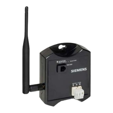
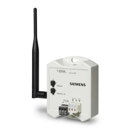
Wireless Transceiver Tool (TLX)
(Version 1.x)
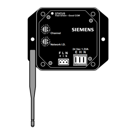
Channel
Network I.D.
WLAN0002R1
RS-232
24 Vac 1.2VA
E H N
Figure 1. Wireless Transceiver Tool (TLX).
Product Description
The Wireless Transceiver Tool (TLX) is a wireless
transceiver that can be used before, during, and
after installation for communication surveys, network
checkout, and troubleshooting.
Through Microsoft®HyperTerminal, you can view
the WFLN information that the TLX gathers, such as
node configuration data and communication quality.
The TLX connects to a laptop computer (cable P/N
540-143) and uses 24 Vac power.
Product Numbers
563-006 Wireless Transceiver Tool (TLX)
with Direct Mount Antenna, Power
Cable, and 24 Vac Transformer
(Version 1.x)
Accessories
540-143 MMI Cable (9-pin to RJ-11, RS-232)
Expected Installation Time
3 minutes
Required Tools and Materials
•Smallflat-blade screwdriver
Prerequisites
• The Channel switch on the TLX is set to the
WFLN Channel.
• The Network ID switch on the TLX is set to the
WFLN Network ID.
• The TLX is within wireless communication
range of the WFLN.
Item Number: 563-032, Rev. BA Page 1 of 4
Document No. 563-032
Installation Instructions
January 12, 2007
Installation
1. Connect the MMI cable (540-143) from the laptop
to the TLX box.
2. Terminate power to the TLX (24 Vac 1.2 VA
connector).
EGreen
HRed
NBlack
3. Connect the 24 Vac transformer to a power
source.
4. Position the TLX antenna in a vertical orientation
(up or down) and ensure it is securely attached.
5. At the laptop, launch HyperTerminal (C:\Program
Files\Accessories\HyperTerminal\Hypertrm.exe).
6. Set communications parameters, as follows:
Connect using: Direct to Comm x
(where x is the number of the Comm port
where the laptop computer cable will connect)
Bits per second: 19200
Data bits: 8
Parity: None
Stop bits: 1
Flow control: None
The installation is complete.
9-pin to RJ-11
RS-232 Cable
P/N: 540-143
Laptop
TLX
TLX Kit
P/N 563-006
(Includes: TLX,
Antenna, Power Cable,
24 Vac Transformer)
WLAN0012R1
Figure 2. TLX Connections.
Page 2 of 4 Siemens Building Technologies, Inc.
Document No. 563-032
Installation Instructions
January 12, 2007
Table 1. Status LED.
LED Blink Pattern Operation Modes
OFF Not powered.
Green—quickly blinking ON and OFF
(every 0.25 seconds)
Powered; is communicating with at least one FPX
or FLNX node.
Green—slowly blinking ON and OFF
(every 1.0 second)
Powered; has no communication with any remote
FPX or FLNX nodes.
Yellow—blinking ON and OFF Powered; running Energy Scan.
Yellow—ON steadily Powered; but is defective.
Table 2. Command Summary.
Command Action/Description
?orHELP Displays the command menu.
SCAN Scans the WFLN for all wireless devices.
CONFIG Displays the configuration properties.
DIAG Displays diagnostic status.
CLEAR Resets device diagnostic counts to zero.
BINDING Displays the binding table.
COST Displays the link costs.
LQI Displays the link quality of the last hop of a message path.
RSSI Displays the received signal strength values for the last hop of a message path.
ENERGY Scans the current RF energy values of the radio channels.
REBOOT Reboots the device.
See theTLXUserGuide(563-001) for more information.
Siemens Building Technologies, Inc. Page 3 of 4
Document No. 563-032
Installation Instructions
January 12, 2007
FCC NOTES:
This device complies with Part 15 of the FCC Rules.
Operation is subject to the following two conditions:
1. This device may not cause harmful interference.
2. This device must accept any interference
received, including interference that may cause
undesired operation.
Changes or modifications not expressly approved by
the party responsible for compliance could void the
user’s authority to operate the equipment.
To comply with FCC’s RF exposure limits for general
population/uncontrolled exposure, the antenna(s)
used for this transmitter must be installed to provide
a separation distance of at least 20 cm from all
persons and must not be co-located or operating in
conjunction with any other antenna or transmitter.
FCC Interference Statement (Part 15.105 (b))
This equipment has been tested and found to comply
with the limits for a Class B digital device, pursuant
to Part 15 of the FCC Rules. These limits are
designed to provide reasonable protection against
harmful interference in a residential installation. This
equipment generates, uses, and can radiate radio
frequency energy and, if not installed and used in
accordance with the instructions, may cause harmful
interference to radio communications. However,
there is no guarantee that interference will not occur
in a particular installation. If this equipment does
cause harmful interference to radio or television
reception, which can be determined by turning the
equipment off and on, the user is encouraged to try
to correct the interference by one of the following
measures:
• Reorient or relocate the receiving antenna.
• Increase the separation between the
equipment and receiver.
• Connect the equipment into an outlet on a
circuit different from that to which the receiver
is connected.
• Consult the dealer or an experienced radio/TV
technician for help.
Industrie Canada Certification:
This device has been designed to operate with
an antenna having a maximum gain of 5dBi. An
antenna having a higher gain is strictly prohibited
per regulations of Industry Canada. The required
antenna impedance is 50Ω.
To reduce potential radio interference to other users,
the antenna type and its gain should be so chosen
that the equivalent isotropically radiated power
(EIRP) is not more than that required for successful
communication.
The Wireless Transceiver Tool (TLX) is to be installed
or replaced by professional installation personnel
only.
Information in this document is based on specifications believed correct at the time of publication. The right is reserved to make changes as
design improvements are introduced. Product or company names mentioned herein may be the trademarks of their respective owners.
© 2007 Siemens Building Technologies, Inc.
Siemens Building Technologies, Inc. Your feedback is important to us. If you have Document No. 563-032
1000 Deerfield Parkway comments about this document, please send Country of Origin: US
Buffalo Grove, IL 60089-4513 them to SBT_technical.editor@siemens.com. Page 4 of 4
U.S.A.
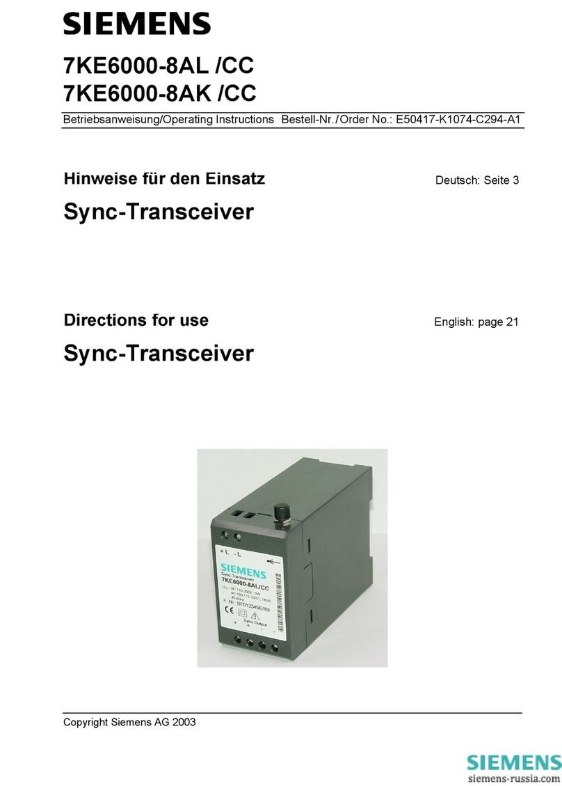
Other manuals for TLX

1

Other Siemens Transceiver manuals

Siemens 563-069 User manual

Siemens

Siemens 563-069 User manual

Siemens PSO 4000 User manual

Siemens

Siemens PSO 4000 User manual

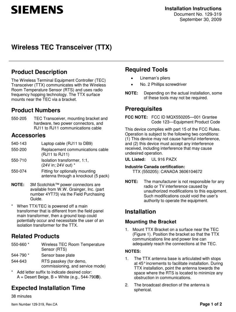
Siemens Wireless TEC Transceiver User manual

Siemens

Siemens Wireless TEC Transceiver User manual

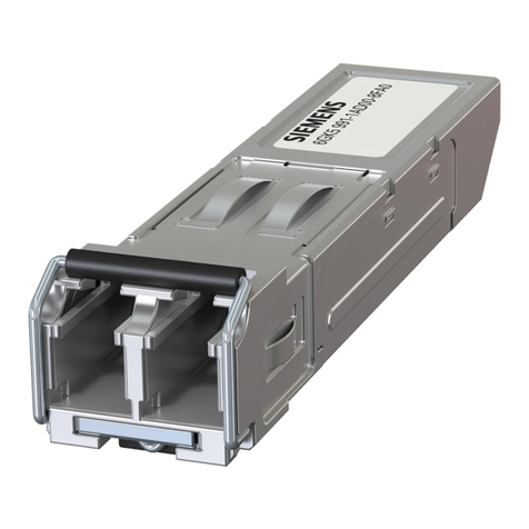
Siemens SIMATIC SFP Series User manual

Siemens

Siemens SIMATIC SFP Series User manual

Siemens SIMATIC NET SFP User manual

Siemens

Siemens SIMATIC NET SFP User manual

Siemens SIMATIC NET SFP Series User manual

Siemens

Siemens SIMATIC NET SFP Series User manual

Siemens WFLN Series User manual

Siemens

Siemens WFLN Series User manual

Siemens 7KE6000-8AL/CC Manual

Siemens

Siemens 7KE6000-8AL/CC Manual

Siemens 563-056 User manual

Siemens

Siemens 563-056 User manual

Siemens 7XV5654-0BA00 Manual

Siemens

Siemens 7XV5654-0BA00 Manual

Siemens FPX User manual

Siemens

Siemens FPX User manual

Siemens SIMATIC NET SFP Series User manual

Siemens

Siemens SIMATIC NET SFP Series User manual

Siemens PSO 4000 User manual

Siemens

Siemens PSO 4000 User manual

Siemens TEC User manual

Siemens

Siemens TEC User manual

Siemens SIMATIC IFP1200 V2 User manual

Siemens

Siemens SIMATIC IFP1200 V2 User manual

Siemens 563-004 User manual

Siemens

Siemens 563-004 User manual

Siemens TLX User manual

Siemens

Siemens TLX User manual

Siemens UP117/12 Service manual

Siemens

Siemens UP117/12 Service manual

Siemens FLNX User manual

Siemens

Siemens FLNX User manual

Siemens 7KE6000-8AK/DD Manual

Siemens

Siemens 7KE6000-8AK/DD Manual

Siemens SITRANS LC500 User manual

Siemens

Siemens SITRANS LC500 User manual

Siemens 7XV5654-0BA00 User manual

Siemens

Siemens 7XV5654-0BA00 User manual

Popular Transceiver manuals by other brands

GEV FlammEx FMF 3170 Assembly

GEV

GEV FlammEx FMF 3170 Assembly

Craig 4103 Service manual

Craig

Craig 4103 Service manual

Icom IC-726 instruction manual

Icom

Icom IC-726 instruction manual

Yaesu FTDX-9000MP Operation manual

Yaesu

Yaesu FTDX-9000MP Operation manual

Vertex Standard VX-2500U Service manual

Vertex Standard

Vertex Standard VX-2500U Service manual

Kenwood ProTalk DIGITAL NX-P1200NV user manual

Kenwood

Kenwood ProTalk DIGITAL NX-P1200NV user manual

GAREX TWOMOBILE MK II operating manual

GAREX

GAREX TWOMOBILE MK II operating manual

Yaesu FTDX101MP Operation manual

Yaesu

Yaesu FTDX101MP Operation manual

Uniden UH785 Series owner's manual

Uniden

Uniden UH785 Series owner's manual

Realistic TRC-449 owner's manual

Realistic

Realistic TRC-449 owner's manual

3Com 3C12065 Installation and use

3Com

3Com 3C12065 Installation and use

Realistic TRC-449 Service manual

Realistic

Realistic TRC-449 Service manual

NETGEAR AGM732F - ProSafe SFP Transceiver Module Product data

NETGEAR

NETGEAR AGM732F - ProSafe SFP Transceiver Module Product data

KELVIN HUGHES CAE-A30/7 Technical manual

KELVIN HUGHES

KELVIN HUGHES CAE-A30/7 Technical manual

Ebyte E62-433T20D user manual

Ebyte

Ebyte E62-433T20D user manual

American Fibertek MT-2400 instruction manual

American Fibertek

American Fibertek MT-2400 instruction manual

Kenwood TS-530S instruction manual

Kenwood

Kenwood TS-530S instruction manual

XIEGU G90 CHEAT SHEET

XIEGU

XIEGU G90 CHEAT SHEET

manuals.online logo
manuals.online logoBrands
  • About & Mission
  • Contact us
  • Privacy Policy
  • Terms and Conditions

Copyright 2025 Manuals.Online. All Rights Reserved.