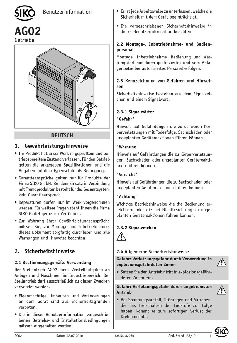
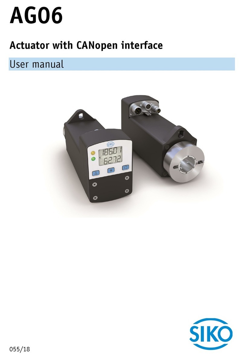
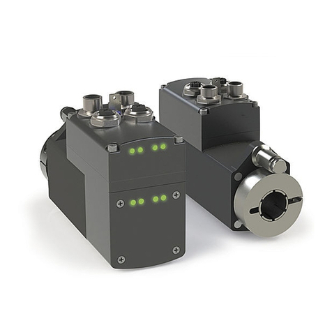
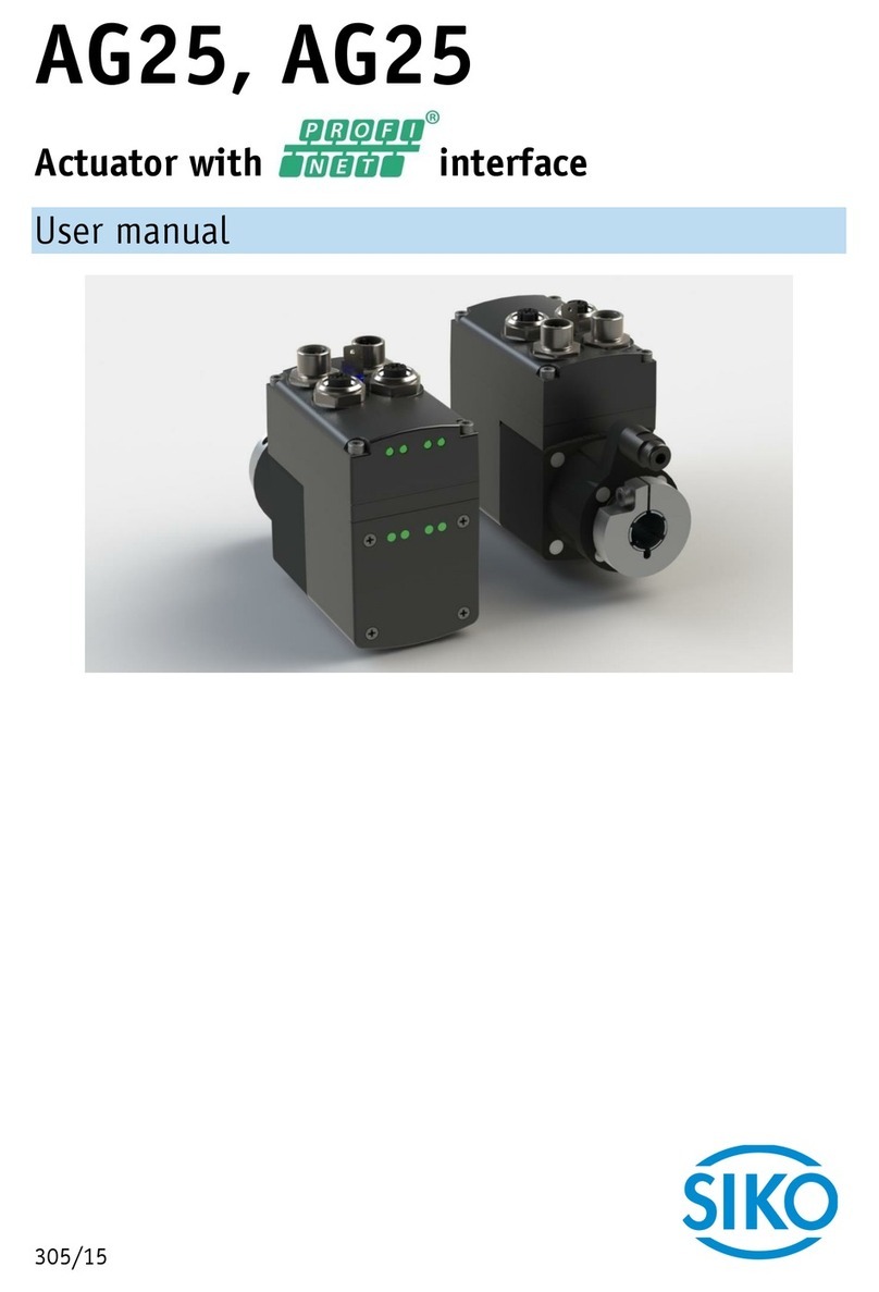
Siko AG24 User manual

225/18
AG24
Actuator with interface
User manual

AG24 Date: 09.07.2018 Art. No. 89255 Mod. status 225/18 Page 2 of 130
Table of contents
1General Information .................................................................................................. 8
1.1 Documentation ........................................................................................................8
2Display and control keys ............................................................................................ 8
2.1 LCD display..............................................................................................................8
2.2 LED display..............................................................................................................9
2.2.1 Status LED 1.........................................................................................................9
2.2.2 Status LED 2.........................................................................................................9
2.2.3 Network status LED 4.............................................................................................9
2.2.4 Link/Activity LED 5, 6..........................................................................................10
2.2.5 Module status LED 7 ............................................................................................10
2.3 Control keys...........................................................................................................10
2.3.1 Key lock and enable time .....................................................................................10
2.3.2 Value input ........................................................................................................11
2.3.3 Value selection ...................................................................................................11
2.4 Menu control .........................................................................................................12
2.4.1 Menu selection ...................................................................................................12
2.4.2 Changeable parameters menu................................................................................13
2.4.2.1 PCM menu ......................................................................................................13
2.4.3 Readable parameters menu ...................................................................................13
2.4.4 Error memory menu .............................................................................................14
3Functional description ............................................................................................. 14
3.1 User units .............................................................................................................14
3.1.1 Example of spindle drive ......................................................................................15
3.1.2 Example of toothed rod/pinion, straight toothing, metric division .............................15
3.1.3 Example external gear..........................................................................................15
3.2 Protective functions................................................................................................16
3.2.1 Current limiting ..................................................................................................16
3.2.2 I2t monitoring....................................................................................................17
3.2.3 Temperature monitoring.......................................................................................17
3.2.4 Overvoltage protection with energetic recovery .......................................................17
3.2.5 Contouring error monitoring .................................................................................17
3.3 Warnings / Errors....................................................................................................18
3.3.1 Warnings ...........................................................................................................18
3.3.2 Errors ................................................................................................................18
3.3.2.1 Error codes .....................................................................................................18
3.4 Operating modes ....................................................................................................19
3.4.1 Positioning mode................................................................................................19
3.4.1.1 Limiting values ...............................................................................................20
3.4.1.2 Limit switch....................................................................................................21
3.4.1.2.1 Example of a configuration............................................................................21
3.4.1.2.2 Assembly of the limit switches.......................................................................22

AG24 Date: 09.07.2018 Art. No. 89255 Mod. status 225/18 Page 3 of 130
3.4.1.3 Loop positioning .............................................................................................22
3.4.1.4 Inching operation............................................................................................23
3.4.1.4.1 Inching operation 1 .....................................................................................23
3.4.1.4.2 Inching operation 2 .....................................................................................24
3.4.1.5 Travel Against Load .........................................................................................24
3.4.1.6 Control word: Positioning mode (master slave)................................................25
3.4.1.7 Status word: Positioning mode (slave master) .................................................26
3.4.1.8 Flow chart: Operating mode Positioning mode .....................................................27
3.4.2 Local control (Stand-Alone Operation) ...................................................................28
3.4.2.1 Inching operation 2.........................................................................................28
3.4.2.2 Specifying the set point ...................................................................................28
3.4.3 Digital inputs and outputs....................................................................................29
3.4.3.1 Examples of digital input configurations.............................................................30
3.4.3.2 Example of digital output configuration..............................................................31
3.4.4 Position Control Mode..........................................................................................31
3.4.4.1 Examples of configuration of the digital inputs for the PCM...................................32
3.4.5 Calibration .........................................................................................................33
3.4.6 Sense of Rotation ...............................................................................................34
3.4.7 Rotational speed mode ........................................................................................34
3.4.7.1 Control word Operating mode: Speed mode..........................................................35
3.4.7.2 Status word Operating mode: Speed mode...........................................................36
3.4.7.3 Flow chart: Operating mode Speed mode.............................................................37
4EtherNet/IP™ .......................................................................................................... 38
4.1 Description............................................................................................................38
4.1.1 IP-Configuration .................................................................................................38
4.1.2 I/O Messages......................................................................................................40
4.1.3 Explicit Messages ................................................................................................40
4.1.4 ADI Object (Class A2h).........................................................................................40
4.2 CIP objects ............................................................................................................41
4.2.1 Identity Object (Class 01h)...................................................................................42
4.2.1.1 Class attributes of the Identity Object ................................................................42
4.2.1.2 Instance attributes of the Identity Object...........................................................42
4.2.1.3 Status............................................................................................................43
4.2.1.4 Reset service of the Identity Object ...................................................................44
4.3 Commissioning aids ................................................................................................44
5Parameters.............................................................................................................. 44
5.1 Positioning............................................................................................................45
5.1.1 Sense of Rotation ...............................................................................................45
5.1.2 Spindle Pitch......................................................................................................45
5.1.3 Gear Ratio Numerator ..........................................................................................46
5.1.4 Gear Ratio Denominator .......................................................................................47
5.1.5 Pos Window........................................................................................................47
5.1.6 Offset Value .......................................................................................................48

AG24 Date: 09.07.2018 Art. No. 89255 Mod. status 225/18 Page 4 of 130
5.1.7 Delta Inch..........................................................................................................48
5.1.8 Inpos Mode........................................................................................................49
5.1.9 Pos Type............................................................................................................50
5.1.10 Loop Length.......................................................................................................50
5.1.11 Calibration Value.................................................................................................51
5.1.12 Control Word ......................................................................................................51
5.1.13 Status Word .......................................................................................................52
5.1.14 Target Value.......................................................................................................53
5.1.15 Actual Value.......................................................................................................53
5.1.16 System Status Word.............................................................................................54
5.2 Actuator................................................................................................................56
5.2.1 Operating Mode ..................................................................................................56
5.2.2 A-Pos ................................................................................................................57
5.2.3 V-Pos ................................................................................................................57
5.2.4 D-Pos ................................................................................................................58
5.2.5 A-Inch...............................................................................................................59
5.2.6 V-Inch...............................................................................................................59
5.2.7 Inching 2 Offset .................................................................................................60
5.2.8 A-Rot ................................................................................................................60
5.3 Limiting values ......................................................................................................61
5.3.1 Software Limit 1 .................................................................................................61
5.3.2 Software Limit 2 .................................................................................................62
5.3.3 Peak Current Limit...............................................................................................62
5.3.4 Peak Current Time ...............................................................................................63
5.3.5 Continuous Current..............................................................................................63
5.3.6 Contouring Error Limit .........................................................................................64
5.3.7 Travel Against Load Trigger ..................................................................................64
5.3.8 Travel Against Load Direction ...............................................................................65
5.4 Visualization..........................................................................................................66
5.4.1 Display Orientation .............................................................................................66
5.4.2 Display Divisor....................................................................................................66
5.4.3 Display Divisor Application...................................................................................67
5.4.4 Decimal Places....................................................................................................67
5.4.5 Direction Indication Function ...............................................................................68
5.4.6 Displayed Value 2nd Line .....................................................................................69
5.5 Options.................................................................................................................70
5.5.1 Key Enable Time..................................................................................................70
5.5.2 Key Function Enable ............................................................................................70
5.5.3 Inching 2 Acceleration Type .................................................................................71
5.5.4 Inching 2 Stop Mode ...........................................................................................72
5.5.5 PIN Change ........................................................................................................72
5.5.6 Generic Mapping Parameter ..................................................................................73
5.5.7 Configuration .....................................................................................................74
5.5.8 S-Command........................................................................................................75

AG24 Date: 09.07.2018 Art. No. 89255 Mod. status 225/18 Page 5 of 130
5.6 Controller parameter ...............................................................................................76
5.6.1 Controller Parameter P .........................................................................................76
5.6.2 Controller Parameter I .........................................................................................76
5.6.3 Controller Parameter D.........................................................................................77
5.7 Digital input/output ...............................................................................................78
5.7.1 Digital Input 1 Functionality ................................................................................78
5.7.2 Digital Input 2 Functionality ................................................................................79
5.7.3 Digital Input 3 Functionality ................................................................................79
5.7.4 Digital Input 4 Functionality ................................................................................80
5.7.5 Digital Inputs Polarity .........................................................................................81
5.7.6 Digital Input Functionalities State.........................................................................82
5.7.7 Digital Inputs State.............................................................................................83
5.7.8 Digital Output 1 Functionality...............................................................................83
5.7.9 Digital Outputs Polarity........................................................................................84
5.7.10 Digital Output Functionalities State.......................................................................85
5.7.11 Digital Outputs Control ........................................................................................86
5.7.12 Service Interface Baud Rate..................................................................................86
5.8 Position Control Mode .............................................................................................87
5.8.1 PCM Position 1 ...................................................................................................87
5.8.2 PCM Position 2 ...................................................................................................88
5.8.3 PCM Position 3 ...................................................................................................88
5.8.4 PCM Position 4 ...................................................................................................89
5.8.5 PCM Position 5 ...................................................................................................89
5.8.6 PCM Position 6 ...................................................................................................90
5.8.7 PCM Position 7 ...................................................................................................91
5.8.8 PCM Acceleration 1..............................................................................................91
5.8.9 PCM Acceleration 2..............................................................................................92
5.8.10 PCM Acceleration 3..............................................................................................92
5.8.11 PCM Acceleration 4..............................................................................................93
5.8.12 PCM Acceleration 5..............................................................................................93
5.8.13 PCM Acceleration 6..............................................................................................94
5.8.14 PCM Acceleration 7..............................................................................................95
5.8.15 PCM Velocity 1....................................................................................................95
5.8.16 PCM Velocity 2....................................................................................................96
5.8.17 PCM Velocity 3....................................................................................................96
5.8.18 PCM Velocity 4....................................................................................................97
5.8.19 PCM Velocity 5....................................................................................................98
5.8.20 PCM Velocity 6....................................................................................................98
5.8.21 PCM Velocity 7....................................................................................................99
5.8.22 PCM Deceleration 1 .............................................................................................99
5.8.23 PCM Deceleration 2 ........................................................................................... 100
5.8.24 PCM Deceleration 3 ........................................................................................... 101
5.8.25 PCM Deceleration 4 ........................................................................................... 101
5.8.26 PCM Deceleration 5 ........................................................................................... 102

AG24 Date: 09.07.2018 Art. No. 89255 Mod. status 225/18 Page 6 of 130
5.8.27 PCM Deceleration 6 ........................................................................................... 102
5.8.28 PCM Deceleration 7 ........................................................................................... 103
5.9 Device information ............................................................................................... 104
5.9.1 Output Stage Temperature .................................................................................. 104
5.9.2 Virtual Motor Temperature.................................................................................. 104
5.9.3 Voltage of Control............................................................................................. 105
5.9.4 Voltage of Output Stage..................................................................................... 105
5.9.5 Motor Current ................................................................................................... 106
5.9.6 Actual Position ................................................................................................. 107
5.9.7 Actual Rotational Speed..................................................................................... 107
5.9.8 Overload .......................................................................................................... 108
5.9.9 Actual Contouring Error...................................................................................... 108
5.9.10 Gear Reduction ................................................................................................. 109
5.9.11 Encoder Resolution............................................................................................ 109
5.9.12 Serial Number................................................................................................... 110
5.9.13 SW Motor Controller........................................................................................... 111
5.9.14 SW Ethernet Module .......................................................................................... 111
5.9.15 Production Date................................................................................................ 112
5.9.16 Device ID......................................................................................................... 112
5.9.17 Generic Mapping Channel ................................................................................... 113
5.10 Error memory ....................................................................................................... 114
5.10.1 Number of Errors............................................................................................... 114
5.10.2 Error Number 1 ................................................................................................. 114
5.10.3 Error Number 2 ................................................................................................. 115
5.10.4 Error Number 3 ................................................................................................. 115
5.10.5 Error Number 4 ................................................................................................. 116
5.10.6 Error Number 5 ................................................................................................. 117
5.10.7 Error Number 6 ................................................................................................. 117
5.10.8 Error Number 7 ................................................................................................. 118
5.10.9 Error Number 8 ................................................................................................. 118
5.10.10 Error Number 9 ................................................................................................. 119
5.10.11 Error Number 10................................................................................................ 119
6Service protocol......................................................................................................120
6.1 General Information.............................................................................................. 120
6.1.1 Communication................................................................................................. 120
6.1.2 Settings........................................................................................................... 120
6.1.3 ASCII commands............................................................................................... 120
6.1.4 Responses........................................................................................................ 121
6.2 Commands........................................................................................................... 121
6.2.1 Start travel job ................................................................................................. 121
6.2.2 Start of inching mode1 ...................................................................................... 121
6.2.3 Start inching mode 2 positive travel direction....................................................... 121
6.2.4 Start inching mode 2 negative travel direction ...................................................... 121

AG24 Date: 09.07.2018 Art. No. 89255 Mod. status 225/18 Page 7 of 130
6.2.5 Cancel current travel job in positioning mode ....................................................... 121
6.2.6 Motor stop fast................................................................................................. 122
6.2.7 Motor stop ....................................................................................................... 122
6.2.8 Activate motor ................................................................................................. 122
6.2.9 Factory setting: all parameters............................................................................ 122
6.2.10 Factory setting: Standard parameter .................................................................... 122
6.2.11 Factory setting: Controller parameter ................................................................... 122
6.2.12 Factory setting: Visualization parameters.............................................................. 123
6.2.13 Factory setting: Network parameters .................................................................... 123
6.2.14 Acknowledge error............................................................................................. 123
6.2.15 Calibrate.......................................................................................................... 123
6.2.16 Delete error memory .......................................................................................... 123
6.2.17 Software reset .................................................................................................. 123
6.3 Flow charts.......................................................................................................... 124
6.3.1 Flow chart: Operating mode: Positioning mode...................................................... 124
6.3.2 Flow chart: Operating mode: Speed mode ............................................................. 125
6.4 Error number encoding .......................................................................................... 125
6.5 Examples............................................................................................................. 126
6.5.1 Write and read set point +500............................................................................. 126
6.5.2 Start travel job ................................................................................................. 126
6.6 ASCII command structure ...................................................................................... 126
6.7 Commissioning aids .............................................................................................. 127
7Ethernet Functions .................................................................................................128
7.1 Web server........................................................................................................... 128
7.2 FTP-Server ........................................................................................................... 129
7.3 Secure Host IP Configuration Protocol (Secure HICP) ................................................. 129
8Block diagram ........................................................................................................130

General Information
AG24 Date: 09.07.2018 Art. No. 89255 Mod. status 225/18 Page 8 of 130
1General Information
1.1 Documentation
The following documents are associated with this document:
The data sheet describes the technical data, the dimensions, the pin assignment, the
accessories and the order key.
The installation instructions describe the mechanical and electrical installation with all
safety-relevant conditions and the associated technical specifications.
User manual describing the migration of the actuator into an Industrial Ethernet network
and its commissioning.
You can also download these documents at http://www.siko-global.com/p/ag24.
2Display and control keys
The actuator features a two-line display with special characters and three operating keys
, and .
The actuator can be configured and controlled via the keys.
The two LEDs and inform about the operating status of the actuator.
The four LEDs , , , and inform about the operating status of the Ethernet module.
Fig. 1: Display and control elements
2.1 LCD display
With operating voltage applied to the control unit, the actual value is displayed in the 1st line
and the target value is displayed in the 2nd line (factory setting). The value displayed in the
2nd line can be chosen by means of parameter setting (see chapter 5.4.6). In the positioning
mode, the direction indicators in the display indicate the key to be pressed for the inching
mode to get to the set positioning window (see chapter 5.4.5). For signaling the speed mode,
both direction indicators are activated in the display.

Display and control keys
AG24 Date: 09.07.2018 Art. No. 89255 Mod. status 225/18 Page 9 of 130
2.2 LED display
2.2.1 Status LED 1
If the actual value is unequal after switching on the module and if it is
outside the programmed positioning window, then the LED status is "red" or
"red, flashing" due to volatile storage of the set point. The set point is
initialized with the value 0 after switching on.
LED state
Description
green
Actuator is within the programmed positioning window.
Operating voltage of the output stage is applied.
green, flashing
Actuator is within the programmed position window.
Operating voltage of the output stage missing.
red
Actuator is outside the programmed positioning window.
Operating voltage of the output stage is applied.
red, flashing
Actuator is outside the programmed positioning window.
Operating voltage of the output stage missing.
off
Operating voltage of control missing.
2.2.2 Status LED 2
LED state
Description
green
Operating voltage applied to control, no fault.
red, flashing
Operating voltage applied to control, active fault.
flashing
red/green
Operating voltage of control is applied, switch lock active.
off
Operating voltage of control missing.
2.2.3 Network status LED 4
A test sequence is executed on this LED after switching on the device.
LED state
Description
off
No operating voltage or no IP address.
green
On-line, one or multiple connections established (CIP Class 1 or 3).
green, flashing
On-line, no connection established.
red
Double IP address, fatal error.
red, flashing
On-line, one or multiple connections timeout (CIP Class 1 or 3).

Display and control keys
AG24 Date: 09.07.2018 Art. No. 89255 Mod. status 225/18 Page 10 of 130
2.2.4 Link/Activity LED 5, 6
LED state
Description
off
no connection, no activity
green
connection (100 Mbit/s) established
green, flickers
activity (100 Mbit/s)
yellow
connection (10 Mbit/s) established
yellow, flickers
activity (10 Mbit/s)
2.2.5 Module status LED 7
A test sequence is executed on this LED after switching on the device.
LED state
Description
off
no operating voltage
green
control via scanner
green, flashing
not configured or scanner inactive
red
serious error
red, flashing
Correctable error. The module has been configured but the stored
parameters differ from the parameters presently used.
2.3 Control keys
After applying operating voltage to the control, the actuator will be on the highest level of
the menu structure, the positioning mode will be active (factory setting).
Pressing the - key starts leftward travel (inching operation 2).
Pressing the - key starts rightward travel (inching operation 2).
Releasing the respective key stops travel movement.
Pressing the - key starts the parameter / programming mode.
2.3.1 Key lock and enable time
The access via keys to the functions of Inching mode 2, positioning mode and speed mode
can be generally locked via the Key Function Enable parameter (see chapter 5.5.2). Temporary
locking or enabling is possible via the control word Bit 9. The Key Enable Time parameter
(see chapter 5.5.1) defines the necessary period of holding down the asterisk key until you
get to the menu or until the set point setting via the display is enabled, respectively.

Display and control keys
AG24 Date: 09.07.2018 Art. No. 89255 Mod. status 225/18 Page 11 of 130
2.3.2 Value input
When you enter values via the keys, the display range is limited to -199999
… 999999. If values beyond this range are entered via the network or
service protocol, "FULL" will be displayed when the parameter is called up.
Enter values via the key and the key.
Confirm values entered by pressing the key.
key: decimal place selection
key: value input
2.3.3 Value selection
For some parameters you can select values from a list. Direct value input is not possible there.
Pressing the key, the value can be selected from the list. By pressing the key, the
selection is confirmed.

Display and control keys
AG24 Date: 09.07.2018 Art. No. 89255 Mod. status 225/18 Page 12 of 130
2.4 Menu control
2.4.1 Menu selection
Start
Hold down
key
Key enable time
exprired?
Changeable parameters
PARAM
CHANGE
Read-only parameters
PARAM
RoPARA
Error memory
PARAM
ErrBuF
Changeable
parameters
menu
PIN entry required
Readable
parameters
menu
Error memory
menu
End
yes
no
PIN correct? yes
no
Fig. 2: Menu selection

Display and control keys
AG24 Date: 09.07.2018 Art. No. 89255 Mod. status 225/18 Page 13 of 130
2.4.2 Changeable parameters menu
The changeable parameters menu is structured as follows:
Description
Display
Page
EtherNet/IP
EIP
38
Positioning
POSIT
45
Actuator
DRIVE
56
Limiting values
BOUNDS
61
Visualization
VISUAL
66
Options
OPTION
70
Controller parameter
CONTR
76
Digital input/output
DIG IO
77
Position Control Mode
PCM
87
2.4.2.1 PCM menu
The PCM menu is divided into single sets of parameters. A set of parameters contains a travel
dataset, e. g. PARAM CHANGE \ PCM \ PCM SET 1 \.
Description
Display
PCM Position 1
POS 1
PCM Acceleration 1
ACC 1
PCM Velocity 1
VEL 1
PCM Deceleration 1
DEC 1
2.4.3 Readable parameters menu
The readable parameters menu contains device information.
Description
Display
Chapter
Output Stage Temperature
OS DEG
5.9.1
Virtual Motor Temperature
VM DEG
5.9.2
Voltage of Control
C VOLT
5.9.3
Voltage of Output Stage
P VOLT
5.9.4
Motor Current
MotCur
5.9.5
Actual Position
POS
5.9.6
Actual Rotational Speed
VEL
5.9.7
Overload
OVLOAD
5.9.8
Gear Reduction
REduc
5.9.10
Encoder Resolution
EncRES
5.9.11
Digital Inputs State
DI4321
5.7.7
Digital Output State
DO 1
SW Motor Controller
VErDrv
5.9.13
SW Ethernet Module
VErMod
5.9.14

Functional description
AG24 Date: 09.07.2018 Art. No. 89255 Mod. status 225/18 Page 14 of 130
Description
Display
Chapter
Serial Number
SEr No
5.9.12
Production Date
DtProd
5.9.15
IP Address
IP 1.2 / 3.4
4.1.1
Subnet Mask
SNM 1.2 / 3.4
4.1.1
Gateway Address
GW 1.2 / 3.4
4.1.1
2.4.4 Error memory menu
The error memory menu contains the number and type of errors that occurred
(see chapter 3.3.2.1). Up to ten errors are stored non-volatilely in the error memory. Empty
memory locations are not listed in the menu. The last error is at the lowest position in the
menu.
Description
Display
Number of errors
Err No
Error number 1
Err 01
:
:
Error number 10
Err 10
Example: Err No = 6 > The last error is in the menu entry Err 06.
3Functional description
If there is no upstream control, you can control the drive via keys or digital inputs and service
interface, respectively. You can configure the drive via display and service interface.
3.1 User units
With factory settings, the drive works with 1024 steps per revolution.
If scaling is desired, with no need to consider the internal gearbox, the Spindle Pitch
(see chapter 5.1.2), Gear Ratio Numerator (see chapter 5.1.3) and Gear Ratio Denominator
(see chapter 5.1.4) parameters must be set correspondingly.
The scaled position value is calculated as follows:
The external gear ratio is calculated as follows (see chapter 3.1.3):
Value jumps will occur if scaling exceeds the absolute encoder's basic resolution of 1024 steps
per revolution.
The following condition shall be met for this reason:

Functional description
AG24 Date: 09.07.2018 Art. No. 89255 Mod. status 225/18 Page 15 of 130
The travel range expressed as user units is calculated with the following formula:
3.1.1 Example of spindle drive
Spindle pitch p = 2 mm
The drive is mounted directly to a spindle.
The desired unit of the position value is 1/100 mm.
The Spindle Pitch parameter (see chapter 5.1.2) is calculated with the following formula:
3.1.2 Example of toothed rod/pinion, straight toothing, metric division
Division p = 5 mm
Number of pinion teeth z = 20
The desired unit of the position value is 1/10 mm.
The Spindle Pitch parameter (see chapter 5.1.2) is calculated with the following formula:
3.1.3 Example external gear
If an external gear is used, a factor can be programmed via the parameters Gear Ratio
Numerator (see chapter 5.1.3) and Gear Ratio Denominator (see chapter 5.1.4) in order to
include the gear ratio in position sensing.
The actuator is operated on a gear (Fig. 3) with transmission reduction of 5:1. For this
purpose, the parameters must be programmed as follows:
Parameter Gear Ratio Numerator = 5
Parameter Gear Ratio Denominator = 1

Functional description
AG24 Date: 09.07.2018 Art. No. 89255 Mod. status 225/18 Page 16 of 130
Fig. 3: External gear
Input of an odd gear transmission reduction value is possible according to the following
example:
Transmission reduction = 3.78
Parameter Gear Ratio Numerator = 378
Parameter Gear Ratio Denominator = 100
3.2 Protective functions
3.2.1 Current limiting
The actual motor current cannot be indicated by measuring the supply
current. With cycled output stages, the supply current does not correspond
to the motor current. Actual motor current can be read via the interface.
The current limit is set via parameter Peak Current Limit (see chapter 5.3.3), which serves
primarily for protecting the drive against overload.
With default set, nominal speed indicated on the data sheet is achieved.
Actuator overload results in limiting the motor current to the set value.
As a consequence, the actuator cannot maintain the speed set, the contouring error increases.
The actuator changes to the error status if the contouring error exceeds the contouring error
limit defined by the Contouring Error Limit parameter (see chapter 5.3.6): contouring error.
5 revolution
1 revolution
Gear output
external
gear unit
5:1
M
internal drive

Functional description
AG24 Date: 09.07.2018 Art. No. 89255 Mod. status 225/18 Page 17 of 130
3.2.2 I2t monitoring
I2t monitoring serves the protection of the output stage and gear.
The I2t limit is calculated with the following formula:
The resulting peak current time is calculated with the following formula:
3.2.3 Temperature monitoring
The temperature of the output stage is measured directly on the output stage board. The
output stage is switched off at 90 °C.
The motor temperature is calculated from the motor current based on a thermal model. An
error is triggered when the motor temperature exceeds 105 °C.
3.2.4 Overvoltage protection with energetic recovery
Active overvoltage protection of the operating voltage of the output stage
is effective only with operating voltage of the control switched on.
The response of active overvoltage protection causes immediate
sluggishness of the driving shaft. This shall be considered when the driving
shaft is adjusted manually.
Besides overvoltage protection by means of passive overvoltage protection elements, the
actuator offers also active overvoltage protection of the operating voltage +UB output stage.
In case of voltage rise caused by energetic recovery (e. g., foreign adjustment), the motor
coils will be short-circuited for at least 4 s if the voltage of 32 V is exceeded. Excess energy
will be converted to heat in the motor coils.
3.2.5 Contouring error monitoring
Disturbance variables such as load and friction may lead to the actuator's inability to follow
the calculated travel profile. If the control deviation of the PID-positioning controller exceeds
the value defined by the Contouring Error Limit parameter (see chapter 5.3.6), the contouring
error will be triggered.

Functional description
AG24 Date: 09.07.2018 Art. No. 89255 Mod. status 225/18 Page 18 of 130
3.3 Warnings / Errors
3.3.1 Warnings
Warnings do not influence the operation of the actuator.
Warnings disappear after removing the cause.
Possible warnings:
Current limiting active. The current limiting bit (bit 12) is set in the status word
(see chapter 3.4.1.7).
3.3.2 Errors
Errors cause an immediate stop of drive movement. For drives with the brake option, the brake
is activated. The drive will be activated if there is no brake option.
An error is indicated via the drive status LEDs and the display.
The error bit (Bit 7) is set in the status word
The error messages are entered in the error memory in the order of their detection. The last
10 error messages are displayed when the error memory is full.
The cause of error can be tracked down with the help of the error codes.
3.3.2.1 Error codes
If the error cannot be acknowledged after removal of the cause of error and
the error persists after power-on reset, then the drive must be inspected in
the factory.
Error code
Display
Fault
Trouble shooting
00h
-
No error
07h
C UVLT
Low control electronics voltage
check control operating voltage
08h
C OVLT
Control electronics overvoltage
check control operating voltage
09h
P OVLT
Power electronics overvoltage
check output stage operating
voltage
0Ah
TMP OS
Output stage excess temperature
reduce ambient temperature
reduce load
0Bh
LAG
Contouring error
reduce load
reduce acceleration or speed
0Ch
BLOCK
Output shaft blocked
disengage shaft
10h
Q1OVR
EEPROM queue overrun
internal error
13h
CSEEP
EEPROM check sum
reset parameters to factory
settings
14h
M WDER
Ethernet module watchdog
internal error

Functional description
AG24 Date: 09.07.2018 Art. No. 89255 Mod. status 225/18 Page 19 of 130
Error code
Display
Fault
Trouble shooting
15h
M ERRO
Ethernet module in the ERROR
status while travel job is active
internal error
16h
M EXCE
Ethernet module in EXCEPTION state
internal error
The behavior of the drive when
this fault occurs can be set with
the parameter configuration, bit
6 (see chapter 5.5.7).
17h
ACYTO
Timeout in acyclic data exchange
check cycle time of the control
20h
I2T
I2T limit exceeded
reduce load
reduce acceleration or velocity
21h
TMO MO
Motor overtemperature
reduce load or duty cycle
22h
ENCODR
Encoder error
internal error
Table 1: Error codes
3.4 Operating modes
The following operating modes are distinguished: positioning mode and speed mode.
In the positioning mode, inching operation is additionally available. Drive control via digital
inputs and Position Control Mode is possible independent of the chosen operating mode.
3.4.1 Positioning mode
In the positioning mode, positioning to the specified set point is executed by means of a
ramp function (Fig. 4) calculated on the basis of the actual position as well as the
programmed controller parameters acceleration and speed.
After activating the travel job, the actuator accelerates with the acceleration A-Pos
(see chapter 5.2.2) to velocity V-Pos (see chapter 5.2.3). The measure of delay until reaching
the set point is also A-Pos.
Alternately, the delay D-Pos (see chapter 5.2.4) can also be used to configure a value that
deviates from the acceleration.
The actuator is repositioned to the calculated path by means of PID position controller.
The controller can be optimized and adjusted to the local conditions via the Controller
Parameter P (see chapter 5.6.1), Controller Parameter I (see chapter 5.6.2) and Controller
Parameter D (see chapter 5.6.3) controller parameters.
Changing controller parameters during a positioning process does not influence the current
positioning operation.

Functional description
AG24 Date: 09.07.2018 Art. No. 89255 Mod. status 225/18 Page 20 of 130
Fig. 4: Ramp travel, direct positioning mode
If the actual position is inside the window defined by the Pos Window parameter
(see chapter 5.1.5), this will be signaled by Bit 5 = 1 in the status word. Upon reaching the
programmed window via parameter (see chapter 5.1.8), you can define the behavior of the
actuator.
Fig. 5: Positioning mode
3.4.1.1 Limiting values
Positioning operating mode:
If Software Limit 1 (see chapter 5.3.1) is equal Software Limit 2
(see chapter 5.3.2), then monitoring of the software limiting value is
deactivated. If the resolution of the absolute encoder is exceeded, there will
be a jump of the actual position.
Speed operating mode: insignificant
If the drive's position is outside the operating range defined by Software
Limit 1 and Software Limit 2, then traveling is only enabled in inching mode
in the direction of the operating range.
Start position
Target position
Time
Speed
V-Pos
A-Pos
D-Pos
A-Pos
Software Limit 1
Software Limit 2
Travel range
Upper limit
Travel range
Lower limit
+
-
0
Pos Window
Inpos Mode
-10
+10
Operating range
Other manuals for AG24
1
Table of contents
Other Siko Controllers manuals
