Silca OPERA IV User manual

®
Operating manual
D408570XA
vers.
2.0


Duplicatrice OPERA I - OPERA III - OPERA IV - OPERA 3SF
ALIMENTAZIONE
La duplicatrice deve essere alimentata direttamente da energia elettrica fornita attraverso un dispositivo
di sicurezza. La presa di alimentazione deve essere provvista di collegamento di terra.
DISPOSITIVO DI SICUREZZA
Dispositivo collegato ad una presa di alimentazione provvista di interruttore differenziale; alimenta la
duplicatrice premendo l’interruttore (X1).
Si accende la lampada spia (X2) quando indica la presenza di tensione nella spina (X3).
ATTENZIONE: l’interuttore (X1) è di tipo elettromagnetico, in caso di mancanza di tensione si
spegne automaticamente. Al ritorno della tensione deve essere ripristinato manualmente per
alimentare di nuovo la macchina attraverso la spina (X3).
X Dispositivo di sicurezza
X1 Interruttore generale di sicurezza
X2 Lampada spia
X3 Spina
SCHEMA ELETTRICO
1) Presa dispositivo di sicurezza.
2) Interruttore generale di sicurezza
3) Lampada spia
4) Passacavo
X1
X
X2 X3
3
marrone
azzurro
giallo-verde
marrone
azzurro
OUT
IN
4
1
2

OPERA I - OPERA III - OPERA IV - OPERA 3SF key cutting machine
POWER SUPPLY
The key-cutting machine must be supplied with electricity by means of a safety device. The plug must
be earthed.
SAFETY DEVICE
The device is connected to a power plug with a differential switch, power the key-cutting machine by
pressing the switch (X1).
The warning light (X2) illuminates to indicate voltage in the plug (X3).
ATTENTION: Switch (X1) is electromagnetic, in the event of a power failure it goes out
automatically. When electricity is restored it must be reset manually to power the machine again
by means of the plug (X3).
X Safety device
X1
Main switch
X2
Warning light
X3 Plug
ELECTRICAL CIRCUIT
1) Safety device inlet
2) Safety main switch
3) Warning light
4) Wiring clip
X1
X
X2 X3
3
brown
blue
yellow-green
brown
blue
OUT
IN
4
1
2

AVVERTENZE GENERALI
La duplicatrice é stata progettata nel rispetto dei principi della Direttiva Macchine. Già in fase di progettazione
sono state adottate soluzioni che eliminano i rischi per l’operatore in tutte le fasi di utilizzo: trasporto,
duplicazione, regolazione e manutenzione.
I rischi residui sono stati eliminati con apposite parti protettive per l’operatore.
Le protezioni adottate sono tali da non provocare rischi supplementari e soprattutto non sono eludibili se non
intenzionalmente; dette protezioni non condizionano la visibilità del piano di lavoro.
I materiali usati per la costruzione o impiegati nell’utilizzodella macchina non sono pericolosi e rendono la
duplicatrice conforme alle direttive.
IMPORTANTE!
Per operare in completa sicurezza non utilizzare la duplicatrice prima di aver letto e capito tutti i
concetti, le istruzioni e le regole contenute nel manuale d’uso ed in questo fascicolo in modo da
conoscere perfettamente la duplicatrice, le sue funzioni, le sue limitazioni ed i suoi pericoli.
Conservare questo fascicolo ed assicurarsi che ogni persona che utilizzi la duplicatrice lo legga
attentamente.
NORME DI SICUREZZA:
1)É obbligatorio l’uso di occhiali protettivi durante le operazioni di cifratura; chiavi non correttamente
installate o schegge potrebbero colpire i vostri occhi.
2) Mantenere al proprio posto gli appositi schermi di protezione a bordo macchina.
3) Controllare periodicamente i cavi elettrici; se i cavi sono logorati procedere subito alla
riparazione o sostituzione.
4) Lavorare sempre con mani asciutte, pulite da eventuali residui di grasso od oilo.
5) Scollegare sempre la macchina quando non é in servizio o quando si svolgono operazioni di
manutenzione (es: sostituzione di fresa o spazzola se presente).
6) Non tirare mai violentemente il cavo di alimentazione elettrica ed assicurarsi che non venga a
contatto con olio, oggetti taglienti o calore. Non rimuovere mai dalla spina la messa a terra.
Assicurarsi che il cavo di messa a terra sia sempre ben collegato.
7) Se la duplicatrice viene utilizzata in luoghi aperti, usare sempre una prolunga adatta completa di
cavo di messa a terra.
8) Evitare di utilizzare la duplicatrice in luoghi pericolosi (umidi o bagnati).
Operare sempre in luoghi con buona illuminazione.
9) Non cercare di rimuovere le chiavi grezze o quelle originali dai morsetti se la fresa é ancora in
movimento.
10) Non usare aria compressa per l’eliminazione dei trucioli di cifratura.
11) Tenere pulita l’area di lavoro ed eliminare tutti gli attrezzi di lavoro prima di azionare la
duplicatrice: il disordine può provocare incidenti.
12) Tutti i visitatori soprattutto i bambini devono stare a distanza di sicurezza evitando contatti con la
duplicatrice e i cavi elettrici.
13) Non utilizzare la macchina per impieghi diversi daquelli previsti nel manuale di istruzioni.
14) Non forzare la duplicatrice per nessun motivo; questa svolgerà un lavoro migliore e soprattutto più sicuro.
15) Durante l’uso della duplicatrice indossare abiti appropriati evitando indumenti larghi, cravatte o gioielli che
possano essere catturati dalle parti in movimento.
16) Bloccare in modo adeguato le chiavi nei morsetti. Non tenere con la mano la testa della chiave durante la
duplicazione; se la chiave non risultasse ben bloccata nei morsetti evitare di tagliarla.
17) La fresa deve essere sempre ben affilata; una fresa usurata, oltre che inefficente é anche pericolosa.
18) Fare sempre attenzione al lavoro che si sta svolgendo, evitando di utilizzare la duplicatrice in caso di
stanchezza.
19) Non operare con la duplicatrice sotto effetto di alcool, droghe o medicinali.
20) Non utilizzare la duplicatrice se l’interruttore di accensione e spegnimento non funziona.
21) Conservare queste istruzioni.
I

USO PREVISTO
Le modalità di installazione ed il corretto uso della duplicatrice sono quelli previsti dal costruttore all’interno del manuale di
istruzioni.
Ogni altro impiego della duplicatrice diverso da quello indicato all’interno del manuale, fa decadere tutti i diritti di rivalsa del
Cliente nei confronti della ditta costruttrice e può costituire una fonte di rischio non ponderabile per l’operatore che non la
utilizzi correttamente come per terzi.
Negligenza nell’uso o mancato rispetto da parte dell’operatore delle indicazioni contenute all’interno del manuale, non
rientrano nelle condizioni di garanzia e per esse il costruttore declina ogni responsabilità.
Rischi residui
Nella duplicatrice non sono presenti rischi residui.
Protezioni e cautele per l’operatore
Nelle sue caratteristiche progettuali, la duplicatrice é sicura in tutti i suoi componenti ed é completamente conforme alla
Direttiva Macchine.
Le operazioni per cui la macchina é stata concepita sono facilmente eseguibili senza alcun rischio per l’operatore.
Il rispetto delle norme di sicurezza e delle indicazioni fornite dal costruttore nel presente fascicolo e nel manuale d’uso
non lasciano spazio ad errori umani se non intenzionali.
CARATTERISTICHE DELLA DUPLICATRICE
Rumorosità
Alimentazione
La duplicatrice é alimentata da energia elettrica fornita attraverso una spina separabile con connessione di terra.
La macchina deve essere collegata ad una presa munita di interruttore differenziale.
• Accensione
L’accensione della macchina avviene azionando l’interruttore
generale.
• Identificazione della macchina
La duplicatrice é provvista di targhetta di identificazione
contenente la matricola.
Utilizzare il numero di matricola per richiesta di
eventuali ricambi o manutenzione.
(*) vedi "SMALTIMENTO".
TRASPORTO
La duplicatrice é facilmente trasportabile da una o più persone
(se la massa é superiore ai 25-30 Kg.) e non presenta particolari rischi connessi alla sua movimentazione.
Imballo
L’imballo, costituito all’interno da gusci di materiale espanso, garantisce
condizioni di sicurezza ed integrità per il trasporto della macchina e dei suoi
componenti.
Un robusto cartone esterno ed un involucro di nylon proteggono inoltre la
duplicatrice anche in caso di lungo immagazzinamento.
Trasporto
Il suo imballo permette di evitare i rischi connessi alla movimentazione (urti,
ecc.) ed informa, con opportuna simbologia, sulle condizioni ottimali di
trasporto.
Contenuto dell’imballo
Controllare che il contenuto dell’imballo sia costituito da:
1 duplicatrice racchiusa nei gusci protettivi
1 cavo di alimentazione
1 attrezzatura in dotazione
1 documentazione macchina comprendente:
manuale d’uso, avvertenze generali, foglio ricambi, modulo di garanzia
Si consiglia di conservare il cartone senza danneggiarlo, in quanto esso può essere riutilizzato (trasferimenti della macchina,
spedizioni al costruttore in caso di riparazioni o manutenzioni).
Movimentazione della macchina
Tolta dall’imballo, la duplicatrice va posta sul piano di lavoro. L’operazione può essere eseguita da una o più persone e si
consiglia di non usare prese diverse dal basamento della macchina per la sua movimentazione.
Pressione sonora: Lp (A) = 84,69 dB (A)
Fig. 1
Fig. 2

MANUTENZIONE
ATTENZIONE: in caso di riparazioni o sostituzione di pezzi per manutenzione, la marcatura "CE" e' garantita solo se vengono
utilizzate parti di ricambio originali fornite dal costruttore.
La duplicatrice non necessita di particolari manutenzioni, é comunque opportuno controllare ed eventualmente sostituire
alcune parti soggette ad usura quali: fresa, tastatore, cinghia di trasmissione e spazzola (se presenti).
Sostituzioni: le operazioni sono semplici e possono essere eseguite dall’operatore. I pezzi che devono essere smontati non sono
riposizionabili in modo errato o pericoloso.
Pulizia: si consiglia di tenere puliti carrello e morsetti da trucioli derivanti dalle cifrature utilizzando un pennello. ATTENZIONE: NON
USARE ARIA COMPRESSA!
ATTENZIONE: per una corretta manutenzione della macchina si suggerisce di utilizzare olio protettivo es. WD40 o Similari da
applicare alle parti meccaniche brunite, questo utilizzo previene l’ossidazione delle parti in questione (morsetti, guide,
carrelli...).
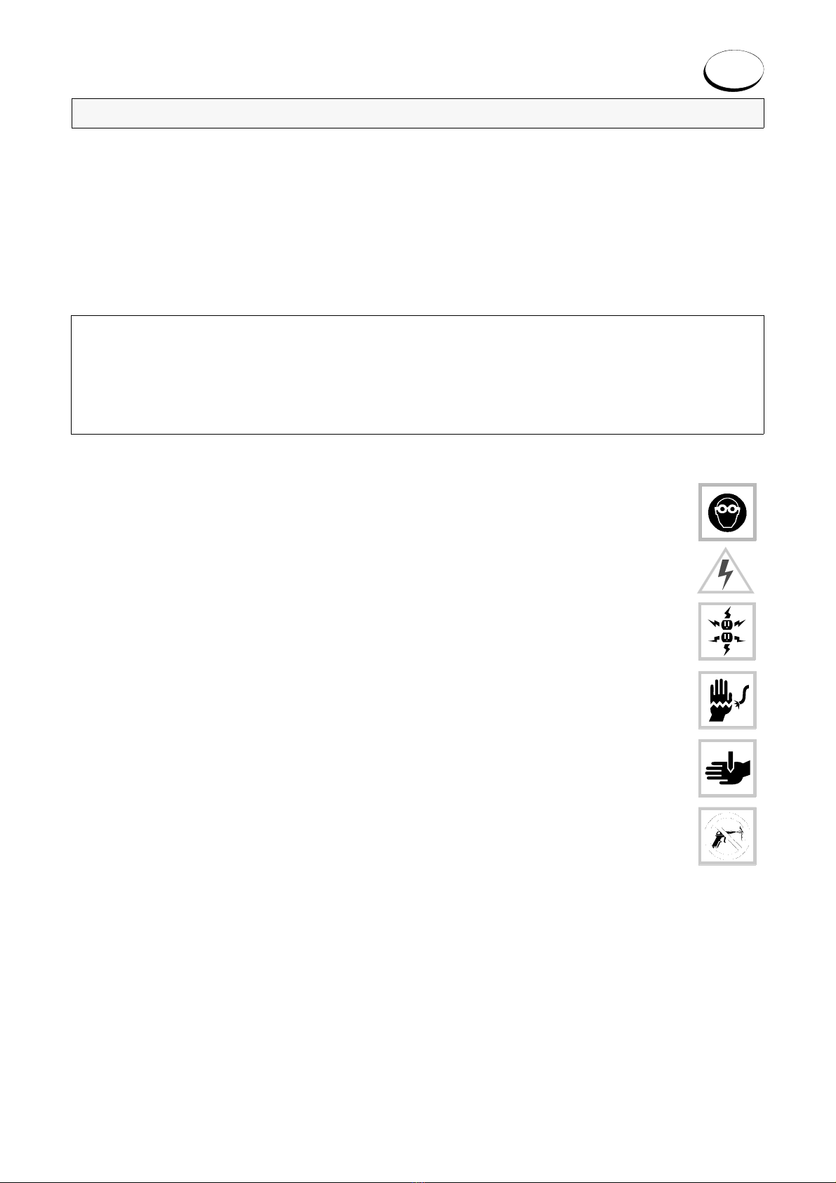
Prima di iniziare qualsiasi operazione di manutenzione leggere attentamente le seguenti avvertenze:
• non eseguire alcuna operazione con la macchina in funzione
• scollegare sempre il cavo di alimentazione
• usare pezzi di ricambio originali
SMALTIMENTO
Per il corretto smaltimento fare riferimento alle norme vigenti.
INFORMAZIONE AGLI UTENTI DI APPARECCHIATURE PROFESSIONALI
Ai sensi dell’art. 24 del Decreto Legislativo 14 marzo 2014, n. 49 "Attuazione della Direttiva 2012/19/UE
sui rifiuti di apparecchiature elettriche ed elettroniche (RAEE
)"
Il simbolo del cassonetto barrato riportato sull’apparecchiatura o sulla sua confezione indica che il prodotto alla fine della
propria vita utile deve essere raccolto separatamente dagli altri rifiuti per permetterne un adeguato trattamento e riciclo.
In particolare, la raccolta differenziata della presente apparecchiatura professionale giunta a fine vita è organizzata e gestita:
a) direttamente dall’utente, nel caso in cui l’apparecchiatura sia stata immessa sul mercato prima del 31 dicembre 2010 e l’utente stesso
decida eliminarla senza sostituirla con una apparecchiatura nuova equivalente ed adibita alle stesse funzioni;
b) dal produttore, inteso come il soggetto che ha per primo introdotto e commercializzato in Italia o rivende in Italia col proprio marchio
l’apparecchiatura nuova che ha sostituito la precedente, nel caso in cui, contestualmente alla decisione di disfarsi dell’apparecchiatura
a fine vita immessa sul mercato prima del 31 dicembre 2010, l’utente effettui un acquisto di un prodotto di tipo equivalente ed adibito
alle stesse funzioni. In tale ultimo caso l’utente potrà richiedere al produttore il ritiro della presente apparecchiatura;
c) dal produttore, inteso come il soggetto che ha per primo introdotto e commercializzato in Italia o rivende in Italia col proprio marchio
l’apparecchiatura nuova che ha sostituito la precedente, nel caso in cui l’apparecchiatura si immessa sul mercato dopo il 31 dicembre
2010;
L’adeguata raccolta differenziata per l’avvio successivo dell’apparecchiatura dismessa al riciclaggio, al trattamento e allo
smaltimento ambientalmente compatibile contribuisce ad evitare possibili effetti negativi sull’ambiente e sulla salute e favorisce
il reimpiego e/o riciclo dei materiali di cui è composta l’apparecchiatura.
Lo smaltimento abusivo del prodotto da parte dell’utente comporta l’applicazione delle sanzioni di cui alla corrente normativa di
legge.
SILCA ha scelto di aderire a Consorzio ReMedia, un primario Sistema Collettivo che garantisce ai consumatori il
corretto trattamento e recupero dei RAEE e la promozione di politiche orientate alla tutela ambientale
.
ASSISTENZA
Silca fornisce agli acquirenti delle sue duplicatrici un’assistenza tecnica adeguata.
Per una totale sicurezza dell’operatore e della macchina, ogni intervento non specificato nel manuale deve essere eseguito dal
costruttore o negli appositi Centri diAssistenza raccomandati da Silca.
A seguire sono riportati i centri diAssistenza specializzati Silca in tutto il mondo.
Modalità di richiesta di intervento
La cedola di garanzia allegata alla duplicatrice assicura interventi di riparazione o sostituzione gratuita di parti difettose nei 24
mesi successivi all’acquisto. Ogni altro intervento deve essere concordato dall’utente con Silca o con i suoi Centri di
Assistenza. Silca é comunque a Vostra disposizione per informazioni tecniche e chiarimenti.


GENERAL INSTRUCTIONS
Our key-cutting machines are designed according to the specifications of the Machine Directives. From the
design stage risks for the operator have been eliminated in all areas: transport, key-cutting, regulation and
maintenance.
Other risks have been eliminated by the use of protective devices for the operator.
The protective devices used are designed not to provoke further risks and, above all, they cannot be ignored
unless deliberately cut out. They do not hinder visibility of the work area.
The materials used in the manufacture of this machine and employed during its use are not dangerous and all
comply with the directives.
IMPORTANT
To operate under conditions of maximum safety do not use the key-cutting machine without reading
and understanding clearly the contents of the Operating Manual and this leaflet; only in this way can
you become familiar with the machine, its functions, limitations and possible dangers.
Keep this leaflet in a safe place and make sure that every person who has to use the key-cutting
machine reads it carefully.
SAFETY REGULATIONS:
1) The use of protective goggles is compulsory during key-cutting operations; badly installed keys or
loose chippings could fly out and damage to the eyes.
2) Always make sure that the protective shields are in place on the machine.
3) Check the electrical wiring periodically; if the wires are worn they should be repaired or replaced.
4) Never work with wet, greasy or oily hands.
5) Disconnect the machine from the mains when it is not in use or in order to carry out maintenance
work (e.g. replacing the cutting tool or brush, if applicable).
6) Never tug at the electricity supply wire and make sure it does not come into contact with oil, sharp
objects or excessive heat.
Never remove the earth wire from the plug and check regularly that it is properly connected.
7) If the key-cutting machine is used outdoors, make sure that the extension is provided with an earth
wire.
8) Do not use the machine in dangerous places (damp or wet) and ensure that it is well illuminated
during operation.
9) Never attempt to remove the key blank or original key from the clamps when the cutting tool is in
motion.
10) Do not use compressed air to remove cutting dust and chippings.
11) Keep the work area clean and free of work tools: untidiness can cause accidents.
12) Do not allow visitors, especially children, to stand near the machine or its wiring; insist that they
keep a safe distance.
13) Do not use the machine for purposes different from those described in the Operating Manual.
14) Never strain the machine for any reason; it will work better and more safely.
15) Wear suitable clothing when using the key-cutting machine, avoiding voluminous garments, ties or jewellery
which could be caught up in the moving parts.
16) Always secure the keys in the clamps properly. Never hold the head of the key during cutting. If the key will not
lock securely into the clamp, do not attempt to cut it.
17) Ensure that the cutting tool is always sharp; a worn, blunt blade is not only inefficient but also dangerous.
18) Always pay careful attention to the work you are doing and do not use the machine if you are tired.
19) Do not operate the machine under the influence of alcohol, drugs or medicines.
20) Do not use the key-cutting machine if the ON/OFF switch is not working properly.
21) Always keep these instructions to hand.
GB

USE
The key-cutting machine must be installed and used in the way laid down by the manufacturer in the Operating Manual.
If the key-cutting machine is used differently or for purposes different from those described in this manual, the customer will
forego any rights he may have over the manufacturer. Furthermore, unforeseen danger to the operator or any third parties may
arise from incorrect use of the machine.
Negligence in the use of the machine or failure on the part of the operator to observe the instructions given in the manual are
not covered by the guarantee and the manufacturer declines all responsibility in such cases.
Further risks
There are no further risks arising from the use of the machine.
Protection and safety precautions for the operator
Our key-cutting machines are designed with features which make it completely safe in all its parts and are built entirely to the
Machine Directives.
The operations for which it has been designed are easily carried out at no risk to the operator.
Observation of safety regulations and the instructions provided by the manufacturer in this leaflet and the Operating Manual
eliminate all human errors, unless deliberate.
MACHINE CHARACTERISTICS
Noise level
Power supply
The machine is supplied with electricity by means of a separable earthed plug.
The key-cutting machine must be connected to a socket provided with a differential switch.
•Start-up
The machine is started up by means of the master switch.
• Machine Identification
The key-cu tting machine is provided with an identification label
which shows the serial number.
Use the serial number when ordering spare parts
or requesting servicing.
(*) see "DISPOSAL".
TRANSPORT
Our key-cutting machines are easily transported by one or
more persons (if the weight is over 25-30 Kg.) and is not dangerous to handle.
Packing
Internally the packing comprises expanded polymer shells which enclose the
machine and its parts, holding them securely in place during handling.
A robust cardboard box and nylon wrapping give further protection to the machine
even for long storage periods.
Transport
The packing protects the machine from the risks of handling (knocks, etc.) and is
clearly marked with suitable symbols showing the ideal conditions for transport.
Contents of packing
Check that the packing box contains:
1 key-cutting machine enclosed in the protective shells
1 supply connecting wire
1 tool kit
1 set of documents, including:
Operating Manual, General Instructions, Spare parts list, Guarantee form
It is advisable to keep the cardboard box in good condition, as it may be used again (e.g. removals, dispatch to the manufactur-
ers for repairs or servicing).
Handling the machine
When the key-cutting machine has been unpacked, place it directly on its workbench. This operation can be carried out by one
or more persons
firmly holding the base, and no other part, to lift and carry the machine.
Noise pressure: Lp (A) = 84,69 dB (A)
Fig. 1
Fig. 2

MAINTENANCE
ATTENTION: for repairs or replacement of parts for maintenance, the ‘CE’ mark is guaranteed only if original spare parts pro-
vided by the manufacturer are used.
Although our key-cutting machines do not require special maintenance, it is advisable to check and, if necessary, replace the
parts subject to wear, such as: cutting tool, tracer point, transmission belt and brush, if applicable.
Replacement: the operations are simple and can be carried out by the operator. The removable parts are so designed as to exclude the pos-
sibility of their being re-assembled or installed wrongly or dangerously.
Cleaning: keep the carriage and clamps free of chippings from the cutting operations by cleaning with a dry brush. WARNING! DO NOT
USE COMPRESSED AIR.
ATTENTION: to keep the machine well maintained we recommend using protective oil, e.g. WD40 or similar, applied to the
burnished mechanical parts. This prevents oxidation of the parts in question (clamps, guides, carriages, etc.).
Before starting any type of maintenance read the instructions below:
• never carry out maintenance or servicing with the machine in motion
• always remove the mains plug
• use original spare parts
DISPOSAL
For correct disposal please refer to current standards.
INFORMATION FOR USERS OF PROFESSIONAL EQUIPMENT
From "Actuation of Directive 2012/19/EU regarding Waste Electrical and Electronic Equipment
(WEEE)"
The symbol of a crossed waste bin found on equipment or its packing indicates that at the end of the product’s useful life it
must be collected separately from other waste so that it can be properly treated and recycled.
In particular, separate collection of this professional equipment when no longer in use is organised and managed:
a) directly by the user when the equipment was placed on the market before 31 December 2010 and the user personally
decides to eliminate it without replacing it with new equivalent equipment designed for the same use;
b) by the manufacturer, that is to say the subject which was the first to introduce and market new equipment that replaces
previous equipment, when the user decides to eliminate equipment placed on the market before 31 December 2010
at the end of its useful life and replace it with an equivalent product designed for the same use. In this latter case the
user may ask the manufacturer to collect the existing equipment;
c) by the manufacturer, that is to say the subject which was the first to introduce and market new equipment that replaces
previous equipment, if it was placed on the market after 31 December 2010;
Suitable separate collection for the purpose of forwarding discarded equipment for recycling, treatment or disposal in an envi-
ronmentally friendly way helps to avoid possible negative effects on the environment and human health and encourages re-use
and/or recycling of the materials making up the equipment.
The sanctions currently provided for by law shall apply to users who dispose of products in unauthorised ways
.
ASSISTANCE
Silca provides full assistance to purchasers of its key-cutting machines. To ensure complete safety for the operator and the
machine, any job not specified in the manual should be carried out by the manufacturer or in the special service centres recom-
mended by Silca.
Below is a list of Silca specialised Service Centres all over the world.
How to request service
The guarantee attached to our key-cutting machines ensures free repairs or replacements of faulty parts within 24 months of
purchase.
All other service calls must be arranged by the customer with Silca or with a Service Centre.
Silca is always at your disposal for technical information or clarification.


Silca S.p.A. - OPERA-IV
1
OPERA - IV
Duplicatrice professionale di chiavi a mappa, doppia
mappa, pompa e chiavi con scanalature verticali.
Caratteristica peculiare é la possibilità di cifrare tutti
questi tipi di chiavi senza cambiare carrello, essendo i
vari morsetti necessari già montati nel carrello di serie.
Ciò facilita e velocizza moltissimo le lavorazioni ren-
dendo OPERA-IV una duplicatrice versatile e completa.
Il tastatore é a regolazione micrometrica, con possibilità
di variare la profondità di cifratura in modo rapido e pre-
ciso.
Gli esclusivi morsetti sono studiati per garantire un
bloccaggio perfetto della chiave.
Risulta inoltre pratico e veloce anche il bloccaggio di
chiavi con gambo a sezione quadra.
La traslazione del carrello avviene tramite un’unica leva
che movimenta una tavola a croce montata su guide a
rulli. Ne consegue massima precisione, durata nel
tempo, sensibilità nei movimenti.
Il motore é a 2 velocità per ottimizzare il rendimento
della fresa su diversi materiali (velocità 1 = acciaio,
velocità 2 = ottone).
Lampada orientabile di serie.
OPERA - IV
Professional key-cutting machine for mortice and bit
keys, double bit keys, pin and pipe keys, and keys with
bullet wards.
The distinguishing feature of this machine is its capacity
to cut all these different types of keys without changing
the carriage, as the necessary clamps are all fitted to
the standard carriage.
This makes for easier and quicker key cutting and
renders the OPERA IV a complete, versatile key-cutting
machine.
The tracer point has micrometric regulation which
makes it possible to vary the cutting depth rapidly and
accurately.
The exclusive clamps are designed to guarantee a per-
fect grip on the key.
Keys with square section shafts are also quickly and
easily locked into the jaws.
The carriage slides by means of a single lever which
moves a cross table mounted on roller tracks.
This system ensures maximum precision, long life, and
sensitivity in the movements of the carriage.
The twin speed motor ensures optimum cutting per-
formance with different materials (speed 1 = steel,
speed 2 = brass).
Fitted with a lamp adjustable to any position.

Silca S.p.A. - OPERA-IV
2
e)
Chiave fissa 27 mm
27 mm spanner
i)
Asta sbloccaggio fresa
Cutting tool release bar
d)
Coppia spine di taratura
Pair of calibrating pins
h)
Chiave esagonale 6 mm
6 mm T shaped Allen key
c)
Coppia calibri di taratura
Pair of setting up calipers
g)
Chiave fissa 17 mm
17 mm spanner
b)
Serie chiavi esagonali (6 pz)
Set of Allen keys (6 pcs)
f)
Chiave fissa 10 mm
10 mm spanner
a)
Set scatola corredo
Tool box
1 - Testa 5 - Fermo 1 - Head 5 - Shoulder
2 - Gambo 6 - Fianco 2 - Shaft 6 - Side
3 - Punta 7 - Scanalature 3 - Tip 7 - Bullet wards
4 - Mappa 4 - Bit
ACCESSORI IN DOTAZIONE / ACCESSORIES PROVIDED
Gambo quadro
Chiave a pompa
Mappa con tagli
verticali
Doppia mappa Mappa
Double bit Bit Square shaft
Pump key
Bit with bullet
wards

Silca S.p.A. - OPERA-IV
3
C-Fresa
D-Tastatore
E-Supporto tastatore
F-Interruttore lampada
G-Interruttore generale
H-Motore
I-Paraschegge
J-Carter cinghia
J1- Carter fresa
L-Leva traslazione carro morsetti
K-Fermo per chiave
M-Morsetto fisso per chiavi a mappa e doppia mappa
M1-Morsetto mobile per chiavi a mappa e doppia mappa
N-Morsetto fisso per scanalature verticali
N1-Morsetto mobile per scanalature verticali
O-Vite bloccaggio chiavi a pompa (morsetto fisso)
P-Manopola chiusura morsetto fisso (mappa)
P1-Manopola chiusura morsetto mobile (mappa)
Q-Manopola bloccaggio morsetto fisso per scanalature ver-
ticali
Q1-Manopola bloccaggio morsetto mobile per scanalature
verticali
R-Leva rotazione morsetto mobile chiavi a mappa/doppia
mappa
R1-Leva movimento morsetto mobile chiavi a pompa e sca-
nalature verticali
S-Pomellobloccaggiomorsettomobilechiaviamappa/dop-
pia mappa
T-Pomello bloccaggio morsetto mobile chiavi a pompa e
scanalature verticali
U-Leve bloccaggio carrello morsetti
V-Leva bloccaggio carrello inferiore movimento asse X
V1-Leva bloccaggio carrello superiore movimento asse Y
W-Morsetto fisso chiavi a pompa
W1-Morsetto mobile chiavi a pompa
PARTI OPERATIVE / WORKING PARTS
F
G
H
C
V1
M1
S
R
KP
1VU
L
Q1
O
D
M
EI
Q
R1
W
W1
N1
P
N
J
T
J1
Fig. 1
C- Cutter
D-Tracer point
E-Tracer point support
F-Lamp switch
G-ON/OFF switch
H-M
otor
I-Protective shield
J-Belt housing
J1- Cutting tool housing
L-Clamp carriage traverse lever
K-Key stop
M-Fixed clamp for bit and double bit key
M1-Mobile clamp for bit and double bit key
N-Fixed clamp for bullet wards
N1-Mobile clamp for bullet wards
O-Locking screw for pump keys (fixed clamp)
P-Fixed clamp locking knob (bit)
P1-Mobile clamp locking knob (bit)
Q-Fixed clamp locking knob for bullet wards
Q1-Mobile clamp locking knob for bullet wards
R-Lever for rotation of mobile clamp for bit/double bit
keys
R1-Lever for movement of mobile clamp for pump
keys and bullet wards
S-Locking knob for mobile clamp for bit/double bit
keys
T-Locking knob for mobile clamp for pump keys and
bullet wards
U-Locking levers for clamps carriage
V-Locking lever for lower carriage X axis
V1-Locking lever for upper carriage Y axis
W-Fixed clamp for pump keys
W1-Mobile clamp for pump keys

Silca S.p.A. - OPERA-IV
4
DATI TECNICI
Motore:a due velocità 1355 - 660 giri,
monofase 220V/50Hz - 0.13 Kw.
Fresa:in acciaio super rapido HSS ø
80x1,5x22
Movimento tavola a croce: su guide a rulli, temprate e
rettificate.
Morsetti:in acciaio temprato.
Tastatore:in acciaio temprato e rettificato.
Trasmissione:tramite cinghia e pulegge dentate.
Dimensioni:profondità 560 mm - larghezza 320
mm - altezza 420 mm
Peso:45 Kg.
OPERAZIONI PRELIMINARI E AVVERTENZE
Installare la duplicatrice su un piano di lavoro stabile e
adatto al peso, assicurandosi che la tensione della linea
elettrica e il sistema di messa a terra siano corretti.
La duplicatrice é attentamente tarata e collaudata prima
della spedizione.
Il montaggio e lo smontaggio delle chiavi deve avvenire a
motore fermo.
Le operazioni di taglio devono avvenire con carter para-
schegge chiuso.
Prima di iniziare le operazioni, sbloccare le leve (V) e (V1)
che tengono bloccati i carrelli asse X e Y.
Si raccomanda di utilizzare le velocità corrette:
velocità 1 = acciaio velocità 2 = ottone
A motore acceso fare attenzione che il tastatore sia sem-
pre in appoggio alla chiave originale onde evitare di rovi-
nare i morsetti.
Ad ogni cambio della fresa o del tastatore procedere al
controllo della taratura della profondità di taglio.
É consigliabile verificare periodicamente la taratura, in fun-
zione dell’utilizzo della macchina.
ATTENZIONE: non avvicinare le mani alla fresa con
motore acceso. La fresa é tagliente.
INSERIMENTO CARRELLO MORSETTI:
Inserire il carrello nell’apposita sede (guida di rondine) e
posizionarlo facendo allineare uno dei tre riferimenti rossi
del carrello con il riferimento (Y) (Fig.2) sulla base della
macchina (1°riferimento: per cifrare chiavi a mappa/doppia
mappa; 2°: per chiavi a pompa; 3°: per scanalature verti-
cali).
TECHNICAL DATA
Motor:twin speed 1355 - 660 rpm, single
phase 220V/50 Hz - 0.13 Kw.
Cutting tool:high speed HSS steel ø 80x1,5x22
Cross table movement: on hardened, ground roller
tracks
Clamps:hardened steel.
Tracer point:hardened, ground steel.
Transmission:belt and cog pulleys.
Dimensions:depth 560 mm - width 320 mm -
height 420 mm
Weight:45 Kg.
PRELIMINARY OPERATIONS AND ADVICE
Place the machine on a solid bench strong enough to take
its weight.
Ensure that the mains voltage is the same as that of the
motor and that the machine is properly eathed.
The machine is set and tested before leaving our work-
shops. Keys must be both fitted and removed with the
motor off.
When cutting is taking place the protective shield must be
down.
Before beginning cutting operations, release the levers
(V) and (V1) which lock the carriages X and Y axes.
Remember to use the correct speed:
speed 1 = steel speed 2 = brass.
With the motor running make sure that the tracer point is
positioned over the original key so as to avoid accidental
damage to the clamps.
Every time the cutting tool or tracer point is changed,
check the cutting depth setting.
It is advisable to check the setting periodically, according
to how frequently the machine is used.
ATTENTION: keep hands away from the cutting tool
when the motor is running: the cutting tool is extremely
sharp.
FITTING THE CLAMP CARRIAGE:
Place the carriage into its seat (dovetail guide) and posi-
tion by aligning one of the three red reference marks on
the carriage with the reference (Y) (Fig.2) on the machine
base. (The first reference is for cutting bit/double bit keys;
the second is for pump keys; the third for bullet wards).
U
Y
Fig. 2

Silca S.p.A. - OPERA-IV
5
R
Fig. 3 Fig. 3b
Z
L1
L
Fig.4 Fig. 5
I
MONTAGGIO DELLE LEVE (R) E (R1):
Avvitare la leva quasi completamente, fino alla posi-
zione ottimale (Fig.3b). Bloccare quindi il dado (Z) uti-
lizzando la chiave in dotazione ("g" vedi pag.2).
FITTING LEVERS (R) AND (R1):
Screw the lever in almost all the way, to the ideal position
(Fig.3b). Tighten nut (Z) using the spanner provided
(“g” see page 2).
MONTAGGIO DELLA LEVA (L):
Inserire la leva (L) nelle apposite sedi e bloccarla con il
dado (L1) (vedi Fig.4).
FITTING LEVER (L):
Insert the lever (L) into its seat and secure in place with
nut (L1) (see Fig.4).
MONTAGGIO DEL PARASCHEGGE (I):
Vedi Fig.5.
FITTING THE PROTECTIVE SHIELD (I):
See Fig.5.

Silca S.p.A. - OPERA-IV
6
TARATURA ASSIALE
Nella duplicatrice OPERA-IV la taratura assiale é fissa,
non necessita quindi di nessuna manutenzione da parte
dell’utilizzatore.
CONTROLLO TARATURA DELLA
PROFONDITÀ DI TAGLIO
Il controllo della taratura di profondità deve essere ese-
guito periodicamente per una perfetta efficienza della
macchina e ad ogni cambio della fresa (per usura o
sostituzione) o del tastatore.
PROCEDIMENTO:
Sbloccare il morsetto mobile (M1) tirando il pomello (S)
verso sinistra; bloccare il morsetto in posizione orizzon-
tale spingendo il pomello (S) verso destra.
Inserire le spine di taratura (X) ("d" pag.2) sui morsetti e
bloccarle con le manopole (P) e (P1); appoggiare il
tastatore contro la spina, far ruotare la fresa a mano in
tutta la sua circonferenza e verificare che sfiori la spina
montata sul morsetto mobile (M1).
Se tale condizione non si verifica, agire come segue:
- Allentare il grano (E2); ruotando la ghiera (E3) si
effettua la regolazione sopra descritta.
- Ruotando la ghiera (E3) in senso orario, la fresa si
allontana dalla spina e viceversa.
- Ogni divisione del tamburo graduato é di 0,05 mm.
- Ottenuto lo sfioramento della fresa, serrare il grano
(E2) e azzerare il tastatore riportando l’indice di
riferimento del volantino (E4) in corrispondenza della
tacca sul tamburo graduato.
- Per fare questo tenere fermo con una mano la parte
zigrinata del volantino (E3) e con l’altra girare la
parte mobile del volantino (E4).
M1
S
XX
P
P1
M
E2
E4
E3
R
Fig. 6
SETTING SPACING
The spacing on the OPERA-IV is fixed.
It is therefore not necessary for the operator to set it.
CHECKING THE CUTTING DEPTH SETTING
To ensure perfect efficiency of the machine the cutting
depth setting must be checked periodically and every
time the cutting tool is changed (when it is worn or must
be replaced) or on changing the tracer point.
PROCEDURE:
Release the mobile clamp (M1) by pulling knob (S) to
the left; lock the clamp in a horizontal position by push-
ing the knob (S) to the right.
Insert the calibrating pins (X) (“d” on page 2) into the
jaws and secure with knobs (P) and (P1); bring the
tracer point into contact with the pin, turn the cutting tool
full circle by hand and check that it skims the pin in the
mobile clamp (M1).
If this is not the case, act as follows:
- Loosen the grub screw (E2); the adjustment
described above is carried out by turning the nut
(E3).
- Turning the nut (E3) clockwise distances the cutting
tool from the pin, and vice versa.
- The drum is graduated into 0,05 mm sections.
- When the cutting tool skims the pin, secure the grub
screw (E2) and zero the tracer point by taking the
reference notch on the handwheel (E4) up to the
notch on the graduated drum.
- To do this hold the knurled part of the handwheel
(E3) with one hand and with the other turn the
mobile part of the handwheel (E4).

Silca S.p.A. - OPERA-IV
7
TASTATORE MICROMETRICO:
La scelta di un tastatore micrometrico su una duplica-
trice di chiavi a mappa, doppia mappa e pompa, oltre a
svolgere una taratura veloce e perfetta, permette
anche di poter risolvere velocemente tutte quelle pic-
cole variazioni di profondità che necessitano le chiavi
usurate.
CIFRATURA DI CHIAVI A MAPPA E
DOPPIA MAPPA
Sbloccare le levette (U) e posizionare il carrello porta
morsetti allineando il riferimento (Y) con il 1° riferi-
mento del carrello (vedi freccia Fig. 7). Ribloccare poi
le levette (U).
MICROMETRIC TRACER POINT:
A micrometric tracer point on a cutting machine for bit/
double bit and pump keys makes it possible not only to
set the cutting depth rapidly and perfectly, but also to
make the tiny depth adjustments sometimes neces-
sary with worn keys.
CUTTING BIT AND DOUBLE BIT KEYS
Open levers (U) and position the clamp carriage by
aligning reference (Y) with the first notch on the car-
riage (see arrow in Fig.7).
Close the levers (U).
UFig. 7
L
Y

Silca S.p.A. - OPERA-IV
8
M
K
P
M1
S
P1
R
A
B
K
Fig. 7b
- Introdurre la chiave originale nella sede del
morsetto fisso (M) spingendo la mappa contro il
fermo (K) e chiuderla con la manopola (P),
facendo attenzione che la mappa sia disposta
orizzontalmente rispetto al morsetto.
- Bloccare il morsetto mobile (M1) in posizione
orizzontale agendo sul pomello (S).
- Introdurre la chiave da duplicare e chiuderla con
la relativa manopola (P1).
- Fare attenzione che la mappa sia disposta
orizzontalmente rispetto al morsetto.
- Sbloccare il morsetto mobile tirando il pomello
(S) e avviare il motore agendo sull’interruttore
(G) (Fig.1 pag.3).
- Alzare la leva (R), portare la chiave (A) in
appoggio al tastatore, facendo avanzare il carro
con la leva di traslazione (L) (Fig.7).
- Procedere alla cifratura della chiave (B)
abbassando lentamente la leva (R).
- Spostare il carro con la leva di traslazione (L) e
continuare con le altre cifrature della chiave
ripetendo l’operazione sopra descritta.
- Place the original key in the fixed clamp (M)
with the bit up against the stop (K).
- Secure the key in place with knob (P), making
sure that the bit is horizontal to the clamp.
- Secure the mobile clamp (M1) in the horizontal
position by means of the knob (S).
- Insert the key to be cut and secure with the
knob (P1).
- Make sure that the bit is horizontal to the
clamp.
- Release the mobile clamp by pulling out knob
(S) and start the motor by means of switch (G)
(Fig.1, page 3).
- Raise lever (R), take the key (A) into contact
with the tracer point, advancing the carriage by
means of the traverse lever (L) (Fig.7).
- Begin cutting the key (B), lowering lever (R)
slowly.
- Move the carriage with the traverse lever (L)
and continue cutting the key by repeating the
operation described above.
Table of contents
Other Silca Cutter manuals

Silca
Silca Futura Auto User manual

Silca
Silca Delta 2000 FO User manual

Silca
Silca Unocode 399 Plus User manual

Silca
Silca FUTURA PRO User manual

Silca
Silca Delta 2000 AY User manual

Silca
Silca Bravo Series User manual

Silca
Silca POKER PRO User manual

Silca
Silca Twister II NA User manual

Silca
Silca Matrix Evo User manual

Silca
Silca OLYMPIC User manual

Silca
Silca UC 199 User manual

Silca
Silca Triax Pro User manual

Silca
Silca FUTURA PRO User manual

Silca
Silca Idea User manual

Silca
Silca Matrix One User manual

Silca
Silca Technica EU User manual

Silca
Silca Unocode PRO User manual

Silca
Silca Unocode 299 User manual

Silca
Silca REKORD User manual

Silca
Silca Rekord AY User manual