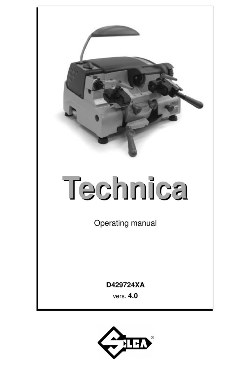
Silca Technica EU User manual

Technica EU
Technica EU
®
D429725XA
vers.
2.0
Operating manual

(c) 2005 SILCA S.p.A. - Vittorio Veneto
This manual has been drawn up by
SILCA S.p.A.
All rights reserved. No part of this publication may be reproduced or used in any form or by any means (photocopying,
microfilm or other) without the written permission of
SILCA S.p.A.
Edition: july 2005
Printed in
Vittorio Veneto
by SILCA S.p.A.
via Podgora, 20 (Z.I.)
31029 VITTORIO VENETO (TV) - Italy

INDEX
GUIDE TO THE MANUAL .........................................................................................................1
GENERAL .................................................................................................................................2
1 MACHINE DESCRIPTION ..........................................................................................4
1.1 Main Characteristics ...........................................................................................4
1.2 Working parts .....................................................................................................5
1.3 Technical Data ...................................................................................................6
1.4 Accessories provided .........................................................................................6
1.5 Safety .................................................................................................................7
1.6 Electric circuit .....................................................................................................7
2 TRANSPORT ..............................................................................................................8
2.1 Packing ...............................................................................................................8
2.2 Unpacking ..........................................................................................................8
2.3 Machine handling ...............................................................................................8
3 MACHINE INSTALLATION AND PREPARATION ....................................................9
3.1 Checking for damage .........................................................................................9
3.2 Positioning ..........................................................................................................9
3.3 Description of work station .................................................................................9
3.4 Environmental conditions ...................................................................................9
3.5 Graphics .............................................................................................................9
4 REGULATION AND USE OF THE MACHINE .........................................................10
4.1 Micrometric tracer point ....................................................................................10
4.2 Tracer point spring ...........................................................................................10
4.3 Right-hand clamp movement ...........................................................................10
4.4 Using the key stops ..........................................................................................11
4.5 Using the jaws ..................................................................................................11
4.6 Checking and gauging ......................................................................................12
4.6.1 A
XIAL GAUGING ON BIT
/
DOUBLE BIT KEYS
...............................................................12
4.6.2 D
EPTH GAUGING
...................................................................................................13
4.7 Cutting operations ............................................................................................14
4.8 Cutting bit and double bit keys - male ..............................................................14
4.9 Cutting bit and double bit keys - female ...........................................................15
5 MAINTENANCE ........................................................................................................16
5.1 Cleaning ...........................................................................................................16
5.2 Carriage replacement .......................................................................................16
5.3 Replacing the tracer point ................................................................................16
5.4 Replacing the cutter .........................................................................................17
5.5 Replacing the brush .........................................................................................17
5.6 Belt replacement and/or tensioning - Belt tightening pulley replacement .........18
5.6.1 B
ELT TIGHTENING PULLEY REPLACEMENT
..............................................................19
5.7 Replacing the master switch ............................................................................19
5.8 Condenser (motor) and/or Feeder (lamp) replacement ....................................20
5.9 Speed commutator ...........................................................................................21
5.9.1 R
EPLACING THE COMMUTATOR
..............................................................................21
5.10 Motor replacement ...........................................................................................22
5.11 Replacing the fuses ..........................................................................................23
5.12 Replacing the light bulb ....................................................................................23
6 DECOMMISSIONING ...............................................................................................24
7 AFTER SALES SERVICE ........................................................................................25
7.1 How to request service .....................................................................................25

Technica EU Operating manual - English
Copyright Silca 2005 1
GUIDE TO THE MANUAL
This manual has been produced to serve as a guide for users of the
TECHNICA EU
key-cutting machine. Read it
carefully; it is essential if you wish to operate your machine safely and efficiently
.
CONSULTATION
-
Description of machine
......................................................................................................... Chapter 1
-
Transport and handling
......................................................................................................... Chapters 2-3
- Regulation and use ................................................................................................................ Chapter 4
- Maintenance ........................................................................................................................... Chapters 5-6
Technical terns
Common technical terms are used in this manual
.
To assist those with little experience of keys and key-cutting, below is an illustration of the terms most frequently
used
.
Fig. 1
1) Head
2) Rim
3) Tip
4) Bit
5) Shoulder
6) Side
1
2
4
35
6

Operating manual - English Technica EU
2 Copyright Silca 2005
GENERAL
TECHNICA EU
has been designed in compliance to the European Community normative (CE)
.
From the design stage, risks for the operator have been eliminated in all areas: transport, regulation, cutting and
maintenance.
Risks have been eliminated by means of protective devices.
The use of protective goggles is compulsory during cutting operations, as indicated on the machine itself and in this
manual.
The materials used to manufacture this machine and all its components are not hazardous
.
USE
The
TECHNICA EU
must be installed and used in the way laid down by the manufacturer
.
If the key-cutting machine is used differently or for purposes different from those described in this manual, the
customer will forego any rights he may have over
Silca
.
Furthermore, unforeseen danger to the operator or any third
parties may arise from incorrect use of the machine
.
Negligence in the use of the machine of failure on the part of the operator to observe the instructions given in this
manual are not covered by the guarantee and the manufacturer declines all responsibility in such cases
.
It is therefore indispensable to read the operating manual carefully in order to make the best use of the
TECHNICA EU and benefit from its potential.
Instructions manual
The instructions manual provided with the machine is essential to its proper use and to carry out the necessary
maintenance.
We therefore recommend protecting the manual from damage in a safe sheltered place, easily to hand for quick
consultation.
Further risks
•
when the machine is in operation only the operator should be close
to it as the moving tools are partially exposed and metal swarf is
generated by machining
.
•
before activating the master switch
(A) (fig. 5, page 5),
the operator
must make sure that the cutter motor starting switch is in position
"0" (fig. 33, page 21).
•
when the machine is in operation, area
"A" (fig. 2)
can be hazardous
for the operator and any third parties in the proximity of the key-
cutting machine if the warnings and precautions given in this
manual are not observed
.
Fig. 2
Protection and safety precautions for the operator
The TECHNICA EU key-cutting machine is entirely built in compliance to the Machine Directives. The operations
for which it has been designed are easily carried out with no risk to the operator.
The adoption of general safety precautions (wearing protective goggles) and observation of the instructions
provided by the manufacturer in this manual eliminate all human error, unless deliberate.
TECHNICA EU
is designed with features which make it completely safe
.
•
Power Supply
The key-cutting machine must be supplied with electricity. The plug must be earthed
.
•
Electric power
The machine is started up by means of the master switch
.
•
Start-up
The speed commutator activates the machine and allows selection of the required speed.
•
Maintenance
The operations to regulate, service, repair and clean the machine are structured in the simplest and safest way
possible. Parts that the operator can dismount cannot be incorrectly replaced therefore avoiding any risks
.
A
A

Technica EU Operating manual - English
Copyright Silca 2005 3
•
Machine identification
The machine
TECHNICA EU
is provided with an identification label which includes the machine’s serial number
(fig.
3).
Fig. 3
MADE IN ITALY
MATRICOLA
SERIAL No
Fax 0438 913800
e-mail [email protected]
SILCA S.p.A.
31029 VITTORIO V.TO (TV) ITALY
TIPO
TYPE
VW
HZ A
Tel. 0438 9136
Manufacturer’s
identity
Serial No.
Type of machine
Absorbed current
Working
frequency Absorbed
power
Year of
manufacture
CE mark
Working
voltage
®
Via PODGORA 20 (Z.I.)

Operating manual - English Technica EU
4 Copyright Silca 2005
1 MACHINE DESCRIPTION
Fig. 4
1.1 Main Characteristics
•KEY-CUTTING UNIT WITH CARRIAGE
The key-cutting unit contains the working parts of the
TECHNICA EU
key-cutting machine, which carry out
reading and cutting of the original key and the necessary finishing off. The working parts are
:
Cutter:
The cutter is the part of the key-cutting machine used to cut keys. It is in super rapid steel (HSS) and is protected
by a special shield to guarantee safety for the operator.
Tracer point unit:
The tracer point is dedicated to reading the cuts on the keys. It is easily regulated (depth and axial gauging).
Carriage:
The carriage comprises a clamp unit for cutting bit and double bit keys.
The carriage movement is horizontal on 2 axes (X-Y) and controlled by means of the lever (L) (fig. 5, page 5).
The knob (R) is used for rounding off bit and double bit keys.
Clamps for bit and double bit male and female keys:
The clamps comprise two self-centering jaws that ensure perfect grip on the stem of bit-double bit and pump keys
(with round or square stems).
•MASTER SWITCH
The master switch is located on the bottom left-hand side of the lamp.
•MOTOR ON SWITCH /SPEED COMMUTATOR
On the top left-hand side there is a switch for starting the motor at the required speed.
•ILLUMINATION
The lamp is fixed and it illuminates the work zone to be used perfectly.

Technica EU Operating manual - English
Copyright Silca 2005 5
1.2 Working parts
Fig. 5
A - master switch
A1- main plug with fuses
B - motor switch / speed commutator
C - cutter
C1- cutting tool housing
D - tracer point
D1- tracer point spring locking knob
D5- ring nut locking knob
E - tracer point support
F - clamp carriage locking levers
G - carriage locking knob
H - motor
I - top cover
L - clamp carriage traverse lever
M - fixed clamp for bit and double bit keys
M1- mobile clamp for bit and double bit keys
M2- head stop
P - fixed clamp locking lever
P1- mobile clamp locking lever
P2- knob for head stop
R - knob for movement of mobile clamp
S - locking lever for mobile clamp
T - lamp
U - brush
V - chippings tray
A
B
C
C1
D
E
F
V
H
L
P
P1
M
S
R
M
TI
U
G
D1
M2
P2
D5
A1

Operating manual - English Technica EU
6 Copyright Silca 2005
1.3 Technical Data
MOTOR:
2 speed single phase
, 230V-50Hz
CUTTER: ø 80 x 1,5 x 22 super rapid steel (HSS)
CUTTER SPEED:
speed
1 = 320
rpm (for steel keys
)
speed
2 = 650
rpm (for brass keys
)
MOVEMENTS: by means of lever and rectified carriage shaft
CLAMPS:
hardened steel
ILLUMINATION:
neon lamp
230V d.c.
DIMENSIONS: width: 440 mm depth: 500 mm height: 420 mm
WEIGHT: Kg. 33
SOUND PRESSURE: Lp (A) = 91 dB (A) max. [brass keys]
Lp (A) = 86,5 dB (A) max. [iron/steel keys]
1.4 Accessories provided
Tool box
D306547AA
5 mm allen key
D300225LR
Key stops ø 7 mm
2 pcs.
D906756ZR (1 pc.)
19 mm spanner
D300783ZZ
6 mm allen key
D300226ZZ
Key stops ø 7-10 mm
2 pcs.
D906757ZR (1 pc.)
2
mm allen key
D300221ZZ
Setting pins
D200470ZZ
Universal centering pins
2 pcs.
D409825BA
2,5 mm allen key
D300222ZZ
Cutting tool release
bar
D400754BA
fuses
5 Amp - rapid
D310788ZZ
3 mm allen key
D300223ZZ
Single jaws
2 pcs.
D906421ZR (1 pc.)
4 mm allen key
D300224ZZ
Double jaws
2 pcs.
D906400ZR (1 pc.)

Technica EU Operating manual - English
Copyright Silca 2005 7
1.5 Safety
•CUTTER MOTOR PROTECTION
ATTENTION:
the cutter motor is protected from overheating by a device (inside the motor) that stops it when it
reaches a dangerous temperature
.
This condition can occur when the machine motor is left on continuously, with high ambient temperatures
or in severe working conditions. If the cutter motor overheats it cuts out automatically. In such cases
proceed as follows:
a)
turn off the master switch
(A).
b) let the motor cool for at least 2 hours then use the machine normally.
•START-UP
The master switch (A) has a safety function that prevents untimely start-up when voltage returns after a cut-out.
1.6 Electric circuit
1) Main plug with fuses
2) Safe main switch
3) Terminal board
4) Lamp reactor
5) Neon lamp
6) Cutter motor condenser
7) Commutator
8) Motor cut-out safety switch
9) Cutter motor
10)Motor ventilator
()
()
2
1
3
6
8
10
9
7
5
4
MV
0
12
brown
black
brown
blue
black
blue
brown
blue
brown
blue
yellow/green
WVU 3 2 1
-
-
7
8

Operating manual - English Technica EU
8 Copyright Silca 2005
2 TRANSPORT
The
TECHNICA EU
key-cutting machine is easy to transport and is not hazardous to handle.
The packed machine should be carried manually by at least 2 persons.
2.1 Packing
The packing for
TECHNICA EU
is designed to ensure safe transportation and protect the machine and all its parts
.
It comprises a pallet base
(b)
to which the machine is attached, and a cardboard box as a cover
(a) (fig. 6).
The machine is fixed to the base with screwed down brackets to hold it firm during transport and protect it
.
The closed packing is held in place by two straps which hold the cardboard box firmly on the pallet
.
Symbols are printed on the outside of the cardboard box to give instructions and warnings for transportation.
Fig. 6
2.2 Unpacking
To remove the machine from the packing box
:
1)
cut the straps with scissors and remove
.
2)
raise the top part of the cardboard box
.
3) loosen the screws on the front and rear brackets holding the machine on the pallet.
4) use the special spanner to loosen the nuts on the feet by a couple of turns.
5)
remove the metal brackets and tighten the nuts on the feet
.
6)
check the contents of the box, comprising
:
-1
key-cutting machine
- 1 set of documents, including: operating manual, spare parts list and guarantee
- 1 power cable
-1
tools pouch
2.3 Machine handling
WhentheTECHNICAEU keycutting machine has been unpacked, place it directly on its workbench; this operation
should be carried out by at least two people. Take care to lift the machine firmly holding the base, and no other
part.
a
b
Keep dry This side up Don’t use
Handle with care

Technica EU Operating manual - English
Copyright Silca 2005 9
3 MACHINE INSTALLATION AND PREPARATION
The key-cutting machine can be installed by the purchaser and does not require any special skills; some checks
and preparation for use operations have to be carried out by the operator.
3.1 Checking for damage
TECHNICA EU is solid and compact and will not normally damage if transport, unpacking and installation have all
been carried out according to the instructions in this manual. However, it is always advisable to check that the
machine has not suffered any damage.
3.2 Positioning
1) Place the machine on a horizontal surface,
solid enough to take its weight.
2)
to facilitate operation the workbench height
should be about 100 cm
.
3) we recommend leaving clearance of at least 20
cm behind the machine and on each side to
ensure proper ventilation and handling.
4)
check that the weight of the machine is evenly
distributed over the four feet
.
5)
connect the machine power supply cable to the
mains
.
ATTENTION: ensure that the machine voltage is the same
as that of the mains, which must be properly
earthed and provided with a differential
switch.
Fig. 7
3.3 Description of work station
The machine needs only one operator, who has the following controls at his/her disposal:
• Master switch (A) located on the bottom left-hand side of the lamp.
• Motor start switch/commutator (B) located on the left-hand side (near the lamp).
•
levers
:
- lamp carriage traverse lever (L)
- Right-hand clamp lever (R) for rounding off cuts (bit and double bit)
3.4 Environmental conditions
To ensure that the best use is made of the key-cutting machine, certain parameters must be borne in mind:
•
damp, badly ventilated sites should be avoided
.
•
the ideal conditions for the machine are
:
-
temperature: between
+10 and +40˚C
-
relative humidity: approx
60%
3.5 Graphics
Fig. 8
20 cm
20 cm
20 cm
100 cm
THE USE OF PROTECTIVE
GOGGLES IS COMPULSORY
(OFF)
(speed 1) (speed 2)
MOTOR START-UP COMMUTATOR
2 SPEED

Operating manual - English Technica EU
10 Copyright Silca 2005
4 REGULATION AND USE OF THE MACHINE
To get the most out of your key-cutting machine, check gauging periodically.
4.1 Micrometric tracer point
The choice of using a micrometric tracer point on a machine for cutting bit and pump keys allows perfect rapid
reading, as well as prompt resolution of the tiny variations in depth presented by worn keys.
Note: when the 2 ring nuts are turned together, each notch moves them 0.05 mm (with (D1) knob released)
4.2 Tracer point spring
The spring movement facilitates the identification of the cutting space before the cut is made.
• To activate the tracer point spring:
release the tracer point spring locking knob (D1) (fig. 9).
• To disable the tracer point spring:
push the tracer point up against its stop and secure with the knob (D1).
Fig. 9
4.3 Right-hand clamp movement
Fig. 10
[A]
Clamp aligned for gauging and positioning the keys.
Hold the mobile clamp in the horizontal position by pushing knob (S) inwards.
[B]
Rocker clamp for cutting bit/double bit keys (rounding off cuts).
Pull out knob (S) to release the mobile clamp.
D1
S
S
AB

Technica EU Operating manual - English
Copyright Silca 2005 11
4.4 Using the key stops
The TECHNICA EU key-cutting machine is provided with two pairs of key stops: one pair (J) (fig. 11) is already
fitted to the clamps, the other pair (J2) is with the accessories in the tool box.
The difference between them is in the length of the pawl:
- the shorter pawl (J) is for use with keys where the diameter of the shaft is below 7 mm and/or in any case with keys
having a very low first cut.
- key stop (J2) is for use with keys where the diameter of the shaft is above 7 mm.
REPLACING THE KEY STOPS
1) Open clamps (M) and (M1) completely (fig. 15, page 12).
2) Unscrew the grub screws (Q) (fig. 15), remove the key stops and replace them.
3) Tighten the grub screws (Q).
Fig. 11
4.5 Using the jaws
- The double jaws (already fitted to the clamps) are designed to grip mortice and bit or double bit male keys;
- The single jaws (supplied with the machine) are used for cutting female keys.
REPLACING THE JAWS:
1) Open the clamps (M) and (M1) completely by loosening the relative knobs (P) and (P1).
2) Take hold of the jaws with index finger and thumb, press inwards (fig. 12) and pull outwards until they come
out of their seating.
3) To fit the single jaws, follow the instructions illustrated in fig. 13.
4) Check that the jaws are properly seated (they should click into place).
Fig. 12
Fig. 13
J J2

Operating manual - English Technica EU
12 Copyright Silca 2005
4.6 Checking and gauging
There are two types of regulation for the
TECHNICA EU
key-cutting machine, defined as axial gauging and depth
gauging
.
Fig. 14
4.6.1 AXIAL GAUGING ON BIT/DOUBLE BIT KEYS
Axial gauging is regulation of the spaces for the cuts on the key (fig. 14).
Checking axial gauging:
1)
Turn the machine off and unplug it
.
2) Use the knob (S) to lock the right-hand clamp in a horizontal position.
3) Use the handles (P) and (P1) to close the clamps.
4) Lock the tracer point spring.
5) Use the lever (L) to raise the carriage and take the stops (J) for double bit keys up against the right-hand side
of the tracer point and cutter (fig. 15).
The ideal situation is when the internal part of the left-hand stop is up against the right-hand side of the tracer point
and the internal part of the right-hand stop is in contact with the right-hand side of the cutter.
If this is not so, loosen the screw (D2) and use a screwdriver to regulate the screw (D4) (fig. 16) until the ideal
situation is reached.
Fig. 15
Fig. 16
cutting spaces
cutting
depths
S
PLP1
D2 JJ
MM1
Q Q
D4

Technica EU Operating manual - English
Copyright Silca 2005 13
4.6.2 DEPTH GAUGING
Depth calibration is regulation of the cutting depth
(fig. 14, page 12).
Depth gauging should be checked periodically to ensure perfect efficiency for the machine, and whenever the
cutter or tracer point is replaced (due to wear or job changeover
.
CHECKING DEPTH GAUGING
:
1)
Turn the machine off and unplug it
.
2) Use the knob (S) to lock the right-hand clamp in a horizontal position;
3) Place the adjusting pins (provided) on the clamps (fig. 17);
4) Disable the tracer point spring (chap. 4.2, page 10).
5) Release knob (D5) placed on ring nut (N).
6) Raise the carriage and take the setting pins into contact with the tracer point and cutting tool (fig. 17).
7) Turn the cutting tool anticlockwise manually and check that it skims the adjusting pins in several places.
8) If necessary, regulate the cutting depth by means of the tracer point, as described below:
c) turn the nut (N) clockwise to advance the tracer point (cut less deep).
d) turn the nut (N) anticlockwise to move the tracer point back (cut more deep).
9) Repeat these operations until the cutting tool skims the setting pins in several points.
10)Once obtained the corret gauging, lock ring nut (N) by tightening knob (D5).
11)After having locked ring nut (N) turn the other ring nut (N1) until the red indicator is aligned with the notch on
the tracer point.
Note: when the 2 ring nuts are turned together, each notch moves them 0.05 mm (with (D1) knob released).
Fig. 17
S
D1
N
N1
D5

Operating manual - English Technica EU
14 Copyright Silca 2005
4.7 Cutting operations
ATTENTION: to work in complete safety, pay special attention to the following recommendations:
•
start the motor only when all the operations with the carriage have been carried out (securing keys,
etc
.)
• always work with dry hands.
• check that the machine is properly earthed.
• use the protective goggles, even if the cutting tool is fitted with a protective shield.
• keep the hands away from the cutting tool when in motion.
4.8 Cutting bit and double bit keys - male
1) Use the knob (S) to lock the right-hand clamp in a horizontal position.
2) Place the keys into the jaws, pushing them to the right until the bit is in contact with the key stop (Y). Close the
jaws, taking care that the keys are securely fitted into their seating and that the bits of the two keys are parallel.
3) Release the right-hand clamp by pulling out the knob (S).
4) Switch the motor commutator to the correct position (1 = low speed for steel keys, 2 = high speed for brass
keys); turn the machine on and use lever (L) to take the carriage slowly towards the cutter, at the same time
raising lever (R) very slightly. With the clamp positioned lower than the cutter, starting from the right, cut the
key, lowering lever (R) to round off the cut. The spring incorporated in the carriage helps the operator by
returning the rocking clamp to its original cutting condition.
5) Cut the whole bit and remove any burrs at the end of the cutting operation.
6) When the cutting operation is complete, turn the switch to “0” and remove the keys.
7) For double bit keys, turn both keys and repeat the operations described above.
Fig. 18
S
JJ
LR
D1

Technica EU Operating manual - English
Copyright Silca 2005 15
4.9 Cutting bit and double bit keys - female
To cut female keys it is necessary to use the two universal centering pins supplied (chap. 1.4, page 6).
1) Use the knob (S) to lock the right-hand clamp in a horizontal position.
2) Remove the key stops (J) (chap. 4.4, page 11).
3) Remove the double jaws and replace with the single jaws (chap. 4.5, page 11).
4) Lock the tracer point spring using knob (D1).
5) First place a centering pin (K) on the fixed clamp (M) and secure by means of the grub screw (Q); insert the
original key so that the centering pin enters the hole in the shaft and secure loosely with knob (P).
6) Take the carriage to the tracer point and cutter by means of lever (L), rest the key bit against the tracer point
and lock the carriage in this position by means of knob (G).
7) Place the keyblank into the mobile clamp (M1) so that it butts
against the cutter and secure loosely with knob (P1).
8) Insert the centering pin (K) pushing well into the hole in the key
shaft, secure with the grub screw (Q) and tighten knob (P1).
9) Rest the head stop (M2) against the head of the key and secure
by tightening knob (P2) and tightening completely knob (P1); in
this way the key is perfectly secured.
10)Release the tracer point spring.
11)Make sure that the key bit is in the horizontal position.
12)Release the carriage by means of knob (G) and, starting from
the right, cut the key.
Fig. 19
Fig. 20
K
Q
S
M
K
L
P1
G
M1
P
QKQ
D1
P2
M2
R

Operating manual - English Technica EU
16 Copyright Silca 2005
5 MAINTENANCE
ATTENTION: for repairs or replacement of parts for maintenance, the ‘CE’ mark is guaranteed only if original spare parts
provided by the manufacturer are used.
Although the TECHNICA EU key-cutting machine does not require special maintenance, it is advisable to check
and, if necessary, replace the parts subject to wear, such as: the belt, cutting tool, tracer point. Replacement is
simple and can be carried out by the operator.
ATTENTION: to keep the machine well maintained we recommend using protective oil, e.g. WD40 or similar, applied to
the burnished mechanical parts. This prevents oxidation of the parts in question (clamps, guides,
carriages...).
Before starting any type of maintenance (checks or replacements), read the instructions below:
•NEVER CARRY OUT MAINTENANCE OR SERVICING WITH THE MACHINE SWITCHED ON.
•ALWAYS REMOVE THE MAINS PLUG.
•FOLLOW ALL THE INSTRUCTIONS IN THE MANUAL TO THE LETTER.
•USE ORIGINAL SPARE PARTS.
5.1 Cleaning
• keep the carriage and clamps free of chippings from the cutting operations by cleaning with a dry
brush.
• Do not use oily substances or solvents to clean the painted surfaces, clamps or electrical
connectors.
• Under no circumstances must compressed air be used to clear the work area of chippings, as these
may find their way into the working parts of the machine.
5.2 Carriage replacement
ATTENTION: Turn the machine off and unplug it.
1) Loosen the 2 knobs (F) (fig. 21) y two
turns and remove the carriage, pulling it
to the left.
2) Fit the new carriage from left to right, into
the dovetail groove, taking it all the way
in, then secure by tightening the 2 knobs
(F).
3) Check machine gauging.
Fig. 21
5.3 Replacing the tracer point
Proceed as follows to replace the tracer point (D) (fig. 22):
ATTENTION:
turn the machine off and unplug it
.
1) Loosen the screw (D3).
2) Remove the worn tracer point.
3) Fit the new tracer point, pushing all the way in. Ensure that the seat
is clean.
4) Tighten the screw (D3).
5) Re-calibrate the machine, following the procedure described in
chap. 4.6.2, page 13.
Fig. 22
F
D3
D
Table of contents
Other Silca Cutter manuals

Silca
Silca Twister II NA User manual

Silca
Silca FUTURA PRO User manual

Silca
Silca Quattrocode User manual

Silca
Silca OLYMPIC User manual

Silca
Silca FUTURA EDGE User manual

Silca
Silca Fastbit User manual

Silca
Silca Matrix One User manual

Silca
Silca Futura Auto User manual

Silca
Silca Triax Pro User manual

Silca
Silca OPERA IV User manual

Silca
Silca Delta 2000 AY User manual

Silca
Silca Unocode PRO User manual

Silca
Silca Matrix Evo User manual

Silca
Silca REKORD User manual

Silca
Silca Rekord AY User manual

Silca
Silca UC 199 User manual

Silca
Silca Idea User manual

Silca
Silca D429724XA User manual

Silca
Silca Delta 2000 MC User manual

Silca
Silca Unocode 299 User manual