Silca Matrix Evo User manual

Operating Manual
Original Instructions
D439848XA
vers. 4
EN

(c) 2012 SILCA S.p.a. – Vittorio Veneto
This manual has been drawn up by SILCA S.p.a.
All rights reserved. No part of this publication can be reproduced or circulated by any means whatsoever (photocopies, microlm or other) without
the consent of SILCA S.p.a.
Edition: June 2012
Printed at Vittorio Veneto
by SILCA S.p.a.
Via Podgora, 20 (Z.I.)
31029 VITTORIO VENETO (TV) – Italy
The Manufacturer declines any responsibility for possible inaccuracies in this document due to printing or transcription errors. The Manufacturer
reserves the right to alter the information without prior notice, except when they affect safety. This document or any of its parts cannot be copied,
altered or reproduced without written authorization from the Manufacturer. Keep the manual and look after it for the entire life cycle of the machi-
ne.
The information has been drawn up by the manufacturer in his own language (Italian) to provide users with the necessary indications to use the
key-cutting machine independently, economically and safely.
IMPORTANT NOTE: in compliance with current regulations relating to industrial property, we hereby state that the trade-marks or trade names
mentioned in our documentation are the exclusive property of authorized manufacturers of locks and users.
Said trade-marks or trade names are nominated only for the purposes of information so that any lock for which our keys are made can be rapidly
identied.

INDICE
USE OF THE MANUAL....................................................................................................................... 1
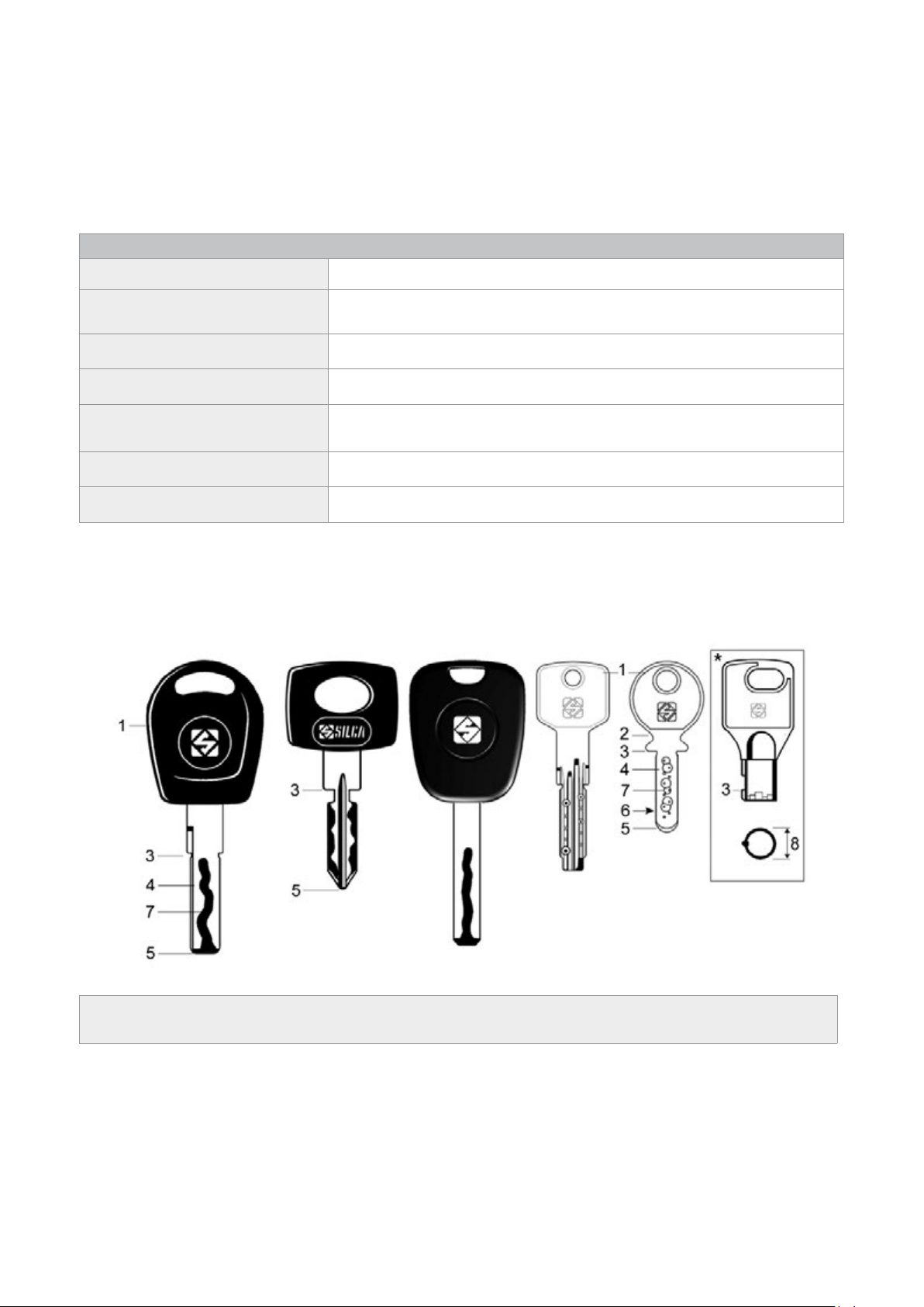
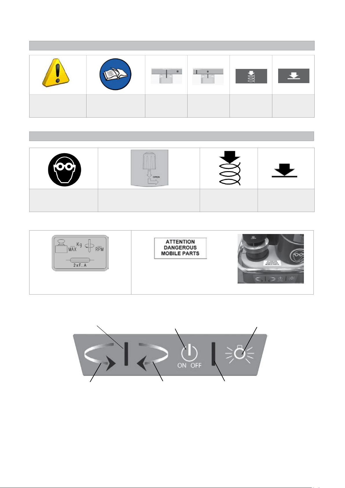
GLOSSARY SYMBOLS-TERMINOLOGY........................................................................................... 2
GENERAL WARNINGS....................................................................................................................... 4
1 MACHINE DESCRIPTION....................................................................................................................5
2 WORKING PARTS - Matrix PRO..........................................................................................................6
3 WORKING PARTS - Matrix EVO..........................................................................................................7
4 ACCESSORIES PROVIDED ................................................................................................................8
4.1 Technical data ...................................................................................................................................8
5 ELECTRIC DIAGRAM .........................................................................................................................9
6 HANDLING .........................................................................................................................................10
6.1 Packing...........................................................................................................................................10
6.2 Transport ........................................................................................................................................10
6.3 Unpacking.......................................................................................................................................10
6.4 Handling the machine.....................................................................................................................10
7 MACHINE INSTALLATION AND PREPARATION ..............................................................................11
7.1 Checking for damage ..................................................................................................................... 11
7.2 Environmental conditions ............................................................................................................... 11
7.3 Positioning...................................................................................................................................... 11
7.4 Safety devices ................................................................................................................................ 11
7.5 Work station description .................................................................................................................12
7.6 Starting the key-cutting machine ....................................................................................................13
7.6.1 Starting the motor.......................................................................................................................... 13
7.6.2 Cutter motor on warning light ........................................................................................................ 13
7.6.3 Led lamp (matrix pro version)........................................................................................................ 13
7.6.4 Led lamp (matrix evo version) ....................................................................................................... 13
8 MACHINE CALIBRATION AND REGULATION ..................................................................................14
8.1 Fitting and removing tools ..............................................................................................................14
8.2 Micrometer gauge...........................................................................................................................15
8.3 Calibration / tool alignment.............................................................................................................16
8.4 Tracer point spring..........................................................................................................................17
8.5 Carriage spring for laser keys.........................................................................................................18
8.6 Clamps ...........................................................................................................................................20
8.6.1 The clamp unit has several seats dedicated to the positioning of different types of keys: ............ 21
9 CUTTING............................................................................................................................................25
9.1 Fitting keys .....................................................................................................................................25
9.2 Key stop..........................................................................................................................................25
9.3 Cutting dimple keys ......................................................................................................................26
9.3.1 Back cuts ..................................................................................................................................... 26
9.3.2 Inclined cuts................................................................................................................................... 27
9.4 Cutting laser type keys ..................................................................................................................28
9.4.1 Cutting laser keys with narrow stems............................................................................................ 29
9.5 Cutting chet type keys (h prole) ..................................................................................................30

9.6 Cutting tubular keys (MATRIX PRO version)..................................................................................31
10 MAINTENANCE..................................................................................................................................32
10.1 Tightening and replacing the belt ...................................................................................................32
10.2 Removing the upper front unit ........................................................................................................33
10.3 Replacing the rollbar.......................................................................................................................33
10.4 Replacing the transparent safety shield .........................................................................................34
10.5 Replacing the lamp.........................................................................................................................34
10.6 Adjusting/replacing the vertical carriage spring..............................................................................35
10.7 Checking and replacing fuses ........................................................................................................36
10.8 Replacing the calibration key pad electronic circuit board..............................................................37
10.9 Replacing the condenser................................................................................................................37
10.10
Replacing the motor .......................................................................................................................38
10.11 Replacing the transformer ..............................................................................................................38
10.12
Replacing switches: master and motor on......................................................................................39
10.13
Aligning/calibrating the clamp.........................................................................................................40
10.13.1 Control alignment left-hand stationary jaws............................................................................... 40
10.13.2 Control alignment right-hand stationary jaws ............................................................................ 41
10.14 Replacing the jaws .........................................................................................................................42
10.14.1 Replacing the left-hand stationary jaws..................................................................................... 42
10.14.2 Replacing right-hand stationary jaws......................................................................................... 42
10.14.3 Replacing left-hand clamp mobile jaw....................................................................................... 43
10.14.4 Replacing right-hand mobile clamp jaw..................................................................................... 43
11 DISPOSAL ..........................................................................................................................................44
12 AFTER-SALES SERVICE ..................................................................................................................45
12.1 How to apply for after-sales service ...............................................................................................45

Operating Manual Matrix
Copyright Silca 2012 1
USE OF THE MANUAL
This manual has been drawn up by the Manufacturer and is an integral part of the machine literature.
The manual gives information it is obligatory for the operator to know and which makes it possible to use the
machine safely.
User’s Manual
This user’s manual is provided because it is essential for proper use and maintenance of the machine.
The manual must be kept carefully throughout the life of the machine, including the decommissioning stage. Keep
in a dry place close to the machine where it is always to hand for the operator.
IT IS OBLIGATORY to read the manual carefully before using the machine.
Readers’ characteristics
This manual must be read and its contents acquired by those who will use it.
Manufacturer’s ID
MATRIX has an ID plate located on the back of the machine, showing the serial number.
Fig. 1
(*) See Ch. 11 DISPOSAL.
How to apply for after-sales service
Silca provides purchasers of MATRIX with After-Sales Service.
For the total safety of the operator and machine, any operation not described in the manual must be carried out
by the manufacturer or in the special Service Centres recommended by Silca.
At the end of the manual there is a list of manufacturers’ and authorized Service Centre addresses.
The warranty card attached to the machine covers free repairs or replacement of faulty parts for 24 months from
the date of purchase*. All operations must be agreed by the user with Silca or the Service Centre.
* Damage caused by negligence or wrong use of the machine by the user will null the warranty.

Operating Manual Matrix
Copyright Silca 20122
GLOSSARY SYMBOLS-TERMINOLOGY
To facilitate reading, a glossary is given below of commonly used symbols and terms connected to keys and the
key-cutting machine.
These symbols and terms will be used in the manual with reference to this page, but we advise reading the list
before the rest of the manual.
GLOSSARY
Tools cutters and Tracer Points
Clamp unit clamp set: pull-out tilting clamp unit (right and left hand) for positioning
keys
Vertical carriage spindle unit (tracer point and cutter) with relative support (Z axis)
Clamp carriage clamp support perpendicular carriages (X, Y axes)
Safety shield transparent shield to prevent swarf scattering and (partially) protect the
operator
Front vertical carriage cover
Hole dimple cut on the stem or back of the key
TERMINOLOGY
For those inexperienced in the subject of keys and key cutting, below is an illustration of the most frequently used
terms:
1) Head
2) Neck
3) Stop
4) Stem
5) Tip
6) Back
7) Cuts
8) Diameter
Fig. 2
(*) Matrix PRO only

Operating Manual Matrix
Copyright Silca 2012 3
GRAPHICS IN THE USER’S MANUAL
Pay attention Obligation to read
the manual
Position of
clamp carriage
to the left
Position of
clamp carriage
to the right
Activation of
tracer point
spring
Deactivation
of tracer point
spring
GRAPHICS ON THE MATRIX KEY-CUTTING MACHINE
Obligatory use of
safety goggles
Cuer release
- Matrix PRO only -
Tracer point spring
ON
Tracer point spring
OFF
Adhesive labels
Mass - RPM - Fusibles
Adhesive label
“DANGEROUS MOBILE PARTS”(cap.4)
place the adhesive label
in the way illustrated.
Fig. 3 Fig. 4
Fig. 5
Tool alignment (green) Lamp switch
Tracer point-key contact Cutter-key contact Blue LED for machine live
Calibration control ON
switch

Operating Manual Matrix
Copyright Silca 20124
GENERAL WARNINGS
MATRIX is designed to the principles of European Standards (CE).
Right from the design stage solutions have been adopted to eliminate hazards for the operator in all the stages
of use: handling, regulation, use and maintenance.
The materials used in manufacture and the components employed in using MATRIX are not dangerous and
ensure that the machine complies to current standards.
Silca S.p.A. has also experimented and applied numerous technical solutions that allow the key-cutting machine
to optimize the quality of the cut keys.
To guarantee maintaining these results over time, please follow the instructions below:
•
Observe the procedures described in this manual;
•
Always use Original Silca Tools as they are designed to make the best of MATRIX and provide quality key-
cutting;
•
Use Silca key blanks, made with top quality materials;
•
Have the key-cutting machine checked periodically by an authorized Silca After-Sales Service Centre (list at
the end of this manual); always use Silca Original Spare Parts. Beware of imitations!
NORMAL USE
MATRIX is a key-cutting machine and must be installed and used according to the rules and specications
established by the manufacturer.
Any other use different from that indicated in this manual will cause the forfeiture of all customers’ rights to make
claims on Silca S.p.A. and may be an unknown source of hazard for the operator or third parties.
ATTENTION: Negligent use or failure by the operator to observe the instructions
in this manual are not covered by the warranty and the manufacturer declines any
responsibility in such cases.
RESIDUAL RISKS
On the Matrix key-cutting machine there is a residual risk of injury
in the cutter spindle area (cutter rotating) if the vertical axis for laser
cuts is blocked.
Furthermore, the MATRIX key-cutting machine has residual risks
when gaining access to parts in motion (not fully protected) and the
risk of chippings ying into the air during the key copying process.
These residual risks in the product are reported in special warnings
(“ATTENTION MOVING PART HAZARD”) and involve the obligatory
use of personal protective devices (GOGGLES).
Fig. 6
SAFETY REGULATIONS
• Always disconnect the machine when it is not in use or when performing maintenance operations.
• Check the electrical wiring periodically; replace any wires that show signs of wear.
• Always work with dry hands free of grease or oil.
• Never pull hard on the power lead and make sure it does not come into contract with oil, sharp objects
or heat. Never remove the earth wire from the plug. Make sure the earth wire connection is sound.
• Do not use the machine in dangerous environments (wet or damp).
• All visitors, especially children, must stay at a safe distance from the machine and must never come
into contact with the electric wiring.

Operating Manual Matrix
Copyright Silca 2012 5
1 MACHINE DESCRIPTION
The MATRIX key-cutting machine gives excellent technical performance of great precision.
The standard clamp on MATRIX is used to cut the following types of keys:
• keyswithatorinclineddimplecuts
• keys with laser type cuts
• laser keys with a narrow stem (Mercedes)
• Fichettypekeys(Hprole)(seenote)
• tubular keys (Matrix PRO only)
KEYS WITH DIMPLE CUTS KEYS WITH LASER TYPE CUTS
LASER KEYS WITH A
NARROW STEM (MERCEDES)
FICHET type KEYS
(Hprole)
TUBULAR KEYS
Ø min. 4 mm
Ø max.12 mm
with “M” adapter
STANDARD on vers.120V
OPTIONAL on vers.230V
with “F” adapter
STANDARD on vers.230V
OPTIONAL on vers.120V
STANDARD on Matrix PRO only

Operating Manual Matrix
Copyright Silca 20126
2 WORKING PARTS - MATRIX PRO
Fig. 7
A - clamp carriage (X-Y axes)
A1- clamp locking lever
B - left-hand tilting clamp
B1- right-hand tilting clamp
C - clamp carriage lever (X-Y axes)
D - vertical carriage lever (Z axis)
D1- lever release and motor start button
E - left-hand clamp knob
E1- right-hand clamp knob
F - cutter
G - transparent safety shield
H - clamp carriage locking knob
I - clamp tilt locking lever
J - lamp
K - calibration unit key pad
M - tracer point locking knob
M1- cutter locking knob
N - tracer point spring cam
O - carriage spring knob
P - ON/OFF switch
Q- motor ON switch
R - rollbar
S - tool box
T - tracer point
V - tracer point regulation micrometric ring
W- motor ON warning light
Z - power socket

Operating Manual Matrix
Copyright Silca 2012 7
3 WORKING PARTS - MATRIX EVO
Fig. 8
A - clamp carriage (X-Y axes)
A1- clamp locking lever
B - left-hand tilting clamp
B1- right-hand tilting clamp
C - clamp carriage lever (X-Y axes)
D - vertical carriage lever (Z axis)
D1- lever release and motor ON button
E - left-hand clamp knob
E1- right-hand clamp knob
F - cutter
G - transparent safety shield
H - clamp carriage locking knob
I - clamp tilt locking lever
J - lamp
K - calibration unit key pad
N - tracer point spring cam
O - carriage spring knob
P - ON/OFF switch
Q - motor ON switch
R - rollbar
S - tool box
T - tracer point
V - tracer point regulation micrometric ring
W - motor ON warning light
Z - power socket

Operating Manual Matrix
Copyright Silca 20128
4 ACCESSORIES PROVIDED
MATRIX comes with a series of accessories for use and maintenance (tools, hex wrenches, fuses, etc.) provided
in a special holder:
FICHET adapter “F”
D910534ZR
(STANDARD on vers.230V)
MERCEDES adapter “M”
D910533ZR
(STANDARD on vers.120V)
F1 cutter fuse 2 pcs
2,5 Amp - rapid (230V)
6,3 Amp - rapid (120V/100V)
T1 tracer point 2.5 mm hex wrench
F22 cutter Steel bar
T22 tracer point Calibration pins
fuse 1 pc
500 mA - rapid
Adhesive label
“DANGEROUS
MOBILE PARTS”
4.1 TECHNICAL DATA
Power supply: 230V-50/60Hz - 0,75 Amp. - 170 Watt
100V/120V - 50/60Hz - 2,3 Amp. - 220 Watt
Cutter motor: single phase 1 speed motor 230V - 50/60 Hz
Cutters: Super speed steel
Tool speed: 6000 rpm (for cutters in super speed steel)
Movements: on 3 axes by ball guides
Clamps: tilting with interchangeable plates
Runs: X axis: 40 mm Y axis: 50 mm Z axis: 30 mm
Dimensions: width: 310 mm (maximum lever operating space 400 mm)
depth: 400 mm height: 470 mm
Illumination: LED lamp
Mass: Kg. 24,6
Noise rating: Lp (A) = 70,5 dB (A) brass dimple keys
Lp (A) = 75,9 dB(A) brass keys with laser cuts
Lp (A) = 76,6 dB(A) steel keys with laser cuts

Operating Manual Matrix
Copyright Silca 2012 9
5 ELECTRIC DIAGRAM
Fig. 9
1) Fuses: 2,5 Amp (230V) - 6,3 Amp (100V/120V)
2) Safety switch
3) Terminal board
4) Motor ON/OFF switch
5) Motor 6,3mF (230V) - 14 mF(100V/120V)
6) Motor warning light (LED)
7) Motor safety microswitch
8) Transformer
9) LED circuit
10) LED lamp
11) Tracer point contact
12) Cutter contact
13) Antenna (not on Matrix EVO)
14) Fuse 500 mA - rapid

Operating Manual Matrix
Copyright Silca 201210
6 HANDLING
The MATRIX key-cutting machine is easy to handle and there are no special hazards involved in moving it.
The packed machine can by carried manually by one person.
6.1 PACKING
The packing for the MATRIX key-cutting machine ensures safe handling of
the machine and all its components.
Packing comprises expanded plastic material wrapped around the machine.
The robust cardboard box in which it is placed and the nylon wrapping protect
the machine even when stored for a long period.
Fig. 10
Keep dry Handle with care Up
6.2 TRANSPORT
The symbols on the outside of the cardboard box give indications for transport.
ATTENTION: keep the packing for future machine transfers.
6.3 UNPACKING
To remove the machine from its packing:
1) Cut the strapping with scissors and remove.
2) Open the box carefully without damaging it.
3) Free the machine from the protective shells.
4) Check the contents of the packing, comprising:
-
MATRIX key-cutting machine.
-
Documentation comprising: user’s manual, spare parts sheet, specialist guide and warranty.
-
Power lead.
-
Tool holder.
6.4 HANDLING THE MACHINE
Once removed from its packing place MATRIX directly on the work bench; one person can easily perform this
operation.
ATTENTION: lift the machine by holding onto the base. Never lift the machine by gripping
the clamps, levers or other parts.

Operating Manual Matrix
Copyright Silca 2012 11
7 MACHINE INSTALLATION AND PREPARATION
Installation is the customer’s task and does not require any special skills.
The key-cutting machine is supplied ready for use and does not need calibration except for the tools to be used;
however, the operator is required to make certain checks and prepare the machine for use.
7.1 CHECKING FOR DAMAGE
MATRIX is a solid compact machine and will not break if handling, unpacking and installation are carried out to
the instructions in this manual. However, it is good practice to check that the machine has not been damaged.
7.2 ENVIRONMENTAL CONDITIONS
To make the most of the key-cutting machine, bear in mind the following environmental parameters: it is advisable
for the area to be dry with good air circulation.
The optimum environmental conditions for machine operation are:
-
temperature 10° C to 40° C;
-
relative humidity: approx. 60%.
7.3 POSITIONING
1) Place the key-cutting machine on a solid horizontal work bench suitable for the weight of the machine (24,6
Kg). The work bench should be approximately 100-120 cm high to facilitate access to the working parts. We
recommend leaving at least 30 cm clearance behind and around the machine to ensure good ventilation and
facilitate handling (Fig. 11).
2) Make sure machine voltage is suitable for the mains supply and that the latter is earthed with a differential
switch.
3) Connect the power lead to the machine.
Fig. 11
7.4 SAFETY DEVICES
• ON/OFF master switch (P)
The master switch (P) is electromagnetic and turns the machine off automatically when power fails. When power
returns the switch must be reset manually to provide the machine with voltage.
• Push button (D1) to release the lever and start the motor
When push button (D1) is not activated there is no risk of involuntarily or accidentally moving the lever (D) and
preventing the motor from starting.
• Warning light (W) cutter motor on
The right-hand front part of the machine (behind the clamp unit) has a warning light (W). The warning light ashes
when the cutter motor is on.

Operating Manual Matrix
Copyright Silca 201212
7.5 WORK STATION DESCRIPTION
The machine is operated by a single person using the following controls:
• ON/OFF master switch (P) located on the right-
hand side of the machine.
• Motor ON/OFF switch (Q).
• Vertical carriage lever (D) with push button (D1) to
release the lever and start the motor.
• Clamp unit
• Lever (left-hand) (C)
• Key pad (calibration and illumination) (K)
Fig. 12
• ORGANIZER SHELF (Z)
The top part of the cover incorporates an area for the operator to use as a place for things such as key blanks or
cut keys. It is advisable not to put too many things in this area, as they could accidentally fall off.
• ROLLBAR (R)
The purpose of this special bar is to assist the operator
during key cutting. It is used as a rest for the left hand when
moving the clamp carriage (centering cuts on dimple keys or
cutting path for laser keys). It ensures smooth synchronised
carriage movements during cutting operations.
• TRANSPARENT SAFETY SHIELD (G)
Special plexiglass shield to limit the dispersal of swarf.
• TOOL BOX (S)
In the bottom part of the machine front, under the clamp
unit carriage, there is a tool box with an open part to use as
a handle for pulling out the box. Inside it has 20 spaces for
holding tracer points and cutters, and a larger area for other
small tools and/or keys.
Fig. 13

Operating Manual Matrix
Copyright Silca 2012 13
7.6 STARTING THE KEY-CUTTING MACHINE
1) Connect the power lead.
2) Turn on the key-cutting machine with the master switch (P). A beep sounds and for a second all the warning
lights (leds) on the key pad/control board (K) light up simultaneously on the machine front (blue vertical bar –
green vertical bar -2 red arrows) (Fig. 5).
3) When the beep stops only the blue warning light stays on to indicate that the machine is live.
Note: if the conditions described above do not occur, see chap. 10.7.
7.6.1 STARTING THE MOTOR
With the machine connected and on:
1) press the luminous switch (Q) to power the motor.(Fig. 12).
2) Press the push button (D1) on the vertical axis lever (D) and lower the lever.
ATTENTION: if the motor does not start and the lever (D) will not move, check that the
lever is fully tightened.
Aashingwarninglight(W)signalsthatthemotorison(Ch.7.6.2).Attention:cutterinmotion!
3) To turn off the motor release the lever (D) or turn off one of the 2 switches (P) or (Q).
7.6.2 CUTTER MOTOR ON WARNING LIGHT
There is a warning light (W) on the right-hand part of the machine front (behind the
clamps unit) (Fig. 14). When the cutter motor is on the warning light ashes.
Fig. 14
7.6.3 LED LAMP (MATRIX PRO VERSION)
When the key-cutting machine is turned on the lamp is off.
To turn on the lamp simply take a hand up to the clamp or
spindle area.
The light goes on atuomatically due to a proximity sensor
inside the front part..
This function can be disabled by the operator:
Turning on:
-
lightly touch the lamp button (J1) to keep the light on.
Turning off:
-
lightly touch the lamp button (J1) again; after a few seconds
initial conditions are automatically reset.
Note: every time the machine is turned on the initial
illumination function is reset (turning on by proximity
sensor).
7.6.4 LED LAMP (MATRIX EVO VERSION)
When the key-cutting machine is turned on the lamp is off.
Lightly touch the button (J1) to turn the lamp on or off.
Fig. 15

Operating Manual Matrix
Copyright Silca 201214
8 MACHINE CALIBRATION AND REGULATION
Before carrying out cutting operations the clamps and tools must be regulated. The spring devices on the machine
to facilitate cutting operations for the operator are activated or deactivated according to the type of key to be cut:
• vertical spring for the tracer point used for dimple keys (ch.8.4)
• cross spring for the carriage used for laser keys (ch.8.5)
8.1 FITTING AND REMOVING TOOLS
ATTENTION: carry out this operation with the cutter motor off.
Lever (D) fully raised.
Clamp carriage lever (C) fully down.
Fig. 16
Matrix PRO version
Tracer point
Fitting:
-
insert the tracer point all the way into its spindle,
with numbered ring towards the clamp.
-
Hold the tracer point in this position and turn the
upper knob (M) clockwise to lock.
Removing:
-
turn the knob (M) anti-clockwise to open the self-
centering gripper and remove the tool. Rotate the
knob without exerting pressure until it clicks.
Cutter
Fitting:
-
insert the cutter all the way into its spindle, with
numbered ring towards the clamp.
-
Turn the tool to t it into its seat (anti-rotation
system).
-
Hold the cutter in this position and turn the knob
(M1) clockwise to lock. Do not exert pressure to
turn the knob slightly (M1).
Removing:
-
press knob (M1) lightly downwards and turn anti-
clockwise to open the self-centering gripper and
remove the tool. Do not exert pressure to turn the
knob slightly (M1).
Fig. 17

Operating Manual Matrix
Copyright Silca 2012 15
Matrix EVO version
Tracer point
Fitting:
-
insert the tracer point all the way into the spindle with the numbered ring
towards the clamp.
-
hold the tool in this position and tighten the grub screw (G3) with the hex
wrench provided.
Removing:
-
loosen the grub screw (G3) with the hex wrench and remove the tool.
Fig. 18
Cutter
Fitting:
-
insert the cutter into the spindle with the numbered ring towards the clamp.
-
hold the tool in this position and tighten the grub screw (G4) with the hex wrench.
Removing:
-
loosen the grub screw (G4) with the hex wrench and remove the tool.
8.2 MICROMETER GAUGE
The micrometer gauge is used for tool alignment and also for adjusting small
variations in depths often necessary on worn keys.
After tool alignment (green bar) the depth of cuts can be reduced or increased
by turning the micrometer gauge (V) to the left or right.
Each line on the gauge corresponds to an increase of 0.02 mm.
Fig. 19
• Turn the gauge clockwise to make cuts less
deep.
• Turn the gauge anti-clockwise to make cuts
deeper.

Operating Manual Matrix
Copyright Silca 201216
8.3 CALIBRATION / TOOL ALIGNMENT
Carry out this operation with the key-cutting machine on.
ATTENTION: check that the motor start switch (Q) is off.
1) Check that the clamps are in the horizontal position (ref. 0) (Ch.8.6).
2) Turn the cam (N) clockwise all the way to disable the tracer point spring (Ch.8.4).
3) Fit and secure the two tools (tracer point and cutter) in their respective spindles.
4) Press the button (K1) on the front of the machine to enable the key pad/control board.
Fig. 20
5) Press the lever (D) release button (D1), lower the vertical carriage and take the tools into contact with the clamp
surface (seat of the key)(Fig. 21) There are three possibilities:
• Central green bar illuminated - Green arrows illuminated - CALIBRATION OK
In this case both tools are in contact with the keys and aligned.
Note: from this position it is advisable to turn the gauge (V) clockwise by a couple of clicks.
• Left-hand red arrow illuminated - Tracer point side
In this case only the tracer point is in contact with the key.
Hold the vertical carriage down and turn the gauge (V) anti-clockwise in the direction of the illuminated arrow.
Calibration is complete as soon as the green vertical bar illuminates together with the two green arrows.
• Right-hand red arrow illuminated - Cutter side
In this case only the cutter is in contact with the key.
Hold the vertical carriage down and turn the gauge (V) clockwise in the direction of the illuminated arrow so that
the red light on the left-hand arrow goes on. From this position hold down rmly the right-hand lever and turn the
gauge (V) one click at a time. Calibration is complete as soon as the green vertical bar illuminates together with
the two green arrows.
ATTENTION: at the end of calibration press the button (K1) to disable the key pad/control
board.
6) Now it’s possible to proceed with duplication.
Tool alignment (green)
Cutter - key contact
Tracer point -
key
contact
This manual suits for next models
3
Table of contents
Other Silca Cutter manuals

Silca
Silca FUTURA PRO User manual

Silca
Silca UC 199 User manual

Silca
Silca Futura Auto User manual

Silca
Silca Bravo Series User manual

Silca
Silca FUTURA EDGE User manual

Silca
Silca Matrix One User manual

Silca
Silca Unocode 299 User manual

Silca
Silca Idea User manual

Silca
Silca Quattrocode User manual

Silca
Silca D429724XA User manual

Silca
Silca OPERA IV User manual

Silca
Silca Delta 2000 AY User manual

Silca
Silca Unocode 399 Plus User manual

Silca
Silca Unocode 399 Plus User manual

Silca
Silca Futura Auto User manual

Silca
Silca Technica EU User manual

Silca
Silca POKER PRO User manual

Silca
Silca REKORD User manual

Silca
Silca Rekord AY User manual

Silca
Silca Delta 2000 MC User manual