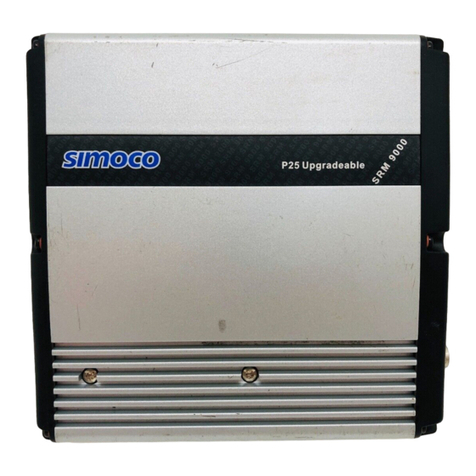
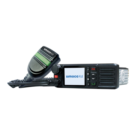
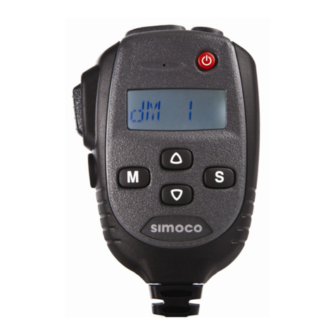
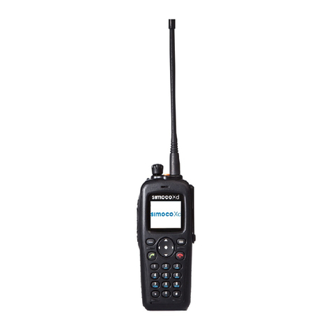
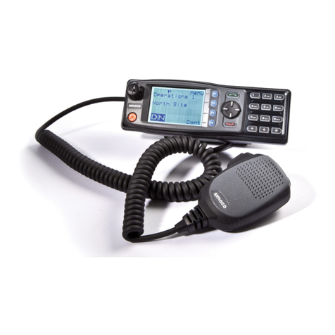
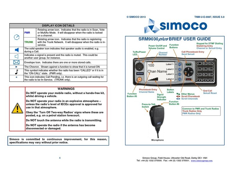
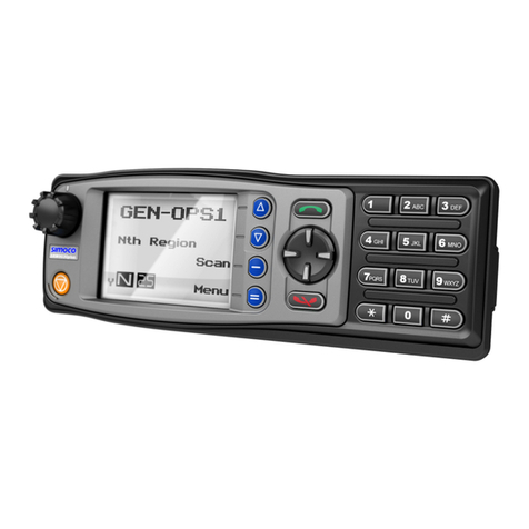
Simoco P25 SRM9030 User manual

P25 SRM9030/SRM9030
Plus
MOBILE
RADIO
P25 –CONVENTIONAL/TRUNKED OPERATING
INSTRUCTIONS
TNM-U-E-0094, Issue 2.0
October 2015
Field House,
Uttoxeter Old Road
Derby
DE1 1NH
Tel: +44 (0) 1332 375500
FAX: +44 (0) 1332 375501
http://www.simocogroup.com
1270 Ferntree Gully Road,
Scoresby
Victoria, 3179
Australia
Tel: +61 (0)3 9730 3999
FAX: +61 (0)3 9730 3988
http://www.simocogroup.com
© Simoco 2015

P25 SRM9030/9030
Plus
–OPERATING INSTRUCTIONS TNM-U-E-0094
Oct 15 (Iss. 2.0) 2 PREFACE
PREFACE
DECLARATION
These Operating Instructions cover the P25 SRM9030/9030Plus Mobile Radio.
Any performance figures quoted are subject to normal manufacturing and service tolerances. The
right is reserved to alter the equipment described in this manual in the light of future technical
development.
Changes or modifications not expressly approved by the party responsible for compliance could
void the user’s authority to operate the equipment.
NOTE.
The manufacturer is not responsible for any radio or television interference caused by
unauthorized modifications to this equipment. Such modifications could void the
user’s authority to operate the equipment.
COPYRIGHT
All information contained in this document is the property of Simoco. All rights are reserved. This
document may not, in whole or in part, be copied, photocopied, reproduced, translated, stored, or
reduced to any electronic medium or machine-readable form, without prior written permission from
Simoco.
DISCLAIMER
There are no warranties extended or granted by this document. Simoco accepts no responsibility
for damage arising from use of the information contained in the document or of the equipment and
software it describes. It is the responsibility of the user to ensure that use of such information,
equipment and software complies with the laws, rules and regulations of the applicable
jurisdictions.
INDUSTRY CANADA –RADIO EQUIPMENT WARNING STATEMENT
This device complies with Industry Canada’s license-exempt RSSs. Operation is subject to the
following two conditions:
(1) This device may not cause interference; and
(2) This device must accept any interference, including interference that may cause undesired
operation of the device.
Le présent appareil est conforme aux CNR d’Industrie Canada applicables aux appareils radio
exempts de licence. L’exploitation est autorisée aux deux conditions suivantes:
(1) L’appareil ne doit pas produire de brouillage; et
(2) L’utilisateur de l’appareil doit accepter tout brouillage radioélectrique subi, même si le
brouillage est susceptible d’en compromettre le fonctionnement.
EQUIPMENT AND MANUAL UPDATES
In the interests of improving the performance, reliability or servicing of the equipment, Simoco
reserves the right to update the equipment or this document or both without prior notice.

P25 SRM9030/9030
Plus
–OPERATING INSTRUCTIONS TNM-U-E-0094
Oct 15 (Iss. 2.0) 3 PREFACE
ERRORS AND OMISSIONS
The usefulness of this publication depends upon the accuracy and completeness of the information
contained within it. Whilst every endeavour has been made to eliminate any errors, some may still
exist. It is requested that any errors or omissions noted should be reported to either of the
following who are part of the Simoco group:
Field House
Uttoxeter Old Road, Derby.
DE1 1NH. UK
1270 Ferntree Gully Road, Scoresby
Victoria. 3179
Australia
Tel: +44 (0) 871 741 1050
Tel: +61 (0)3 9730 3999
E-mail: customer.service@simocogroup.com
E-mail: inquiry.aus@simocogroup.com
DOCUMENT HISTORY
Issue
Date
Comments
1.0
May 2008
Initial Issue.
2.0
30 October 2015
Updates due to Company rebranding. Industry Canada
warning statement added.
ASSOCIATED DOCUMENTS
The following documentation is available for use with the SRM9000 series of products:
TNM-U-E-0079
P25 SRM9030 Mobile Radio Brief User Guide
TNM-P-E-0006
P25 SRM9030 Product Manual
TNM-I-E-0005
SRM9000 Installation Guide
TNM-M-E-0002
SRM9000 Series FM VHF/UHF Mobile Radio Transceiver –
Service Manual (Revision 9 Hardware)
TNM-U-E-0102
SRP9180 Brief User Guide (General)
To order printed copies of this or any of the above publications, please contact Simoco. See the
Support page for contact information.
A comprehensive list of documentation is available for download on the Simoco website
http://www.simocogroup.com via the Partner Portal.

P25 SRM9030/9030
Plus
–OPERATING INSTRUCTIONS TNM-U-E-0094
Oct 15 (Iss. 2.0) Page 4 CONTENTS
TABLE OF CONTENTS
Page
Title Page ...................................................................................................................................... 1
Preface .......................................................................................................................................... 2
Table of Contents (this list) ......................................................................................................... 4
List of Figures .............................................................................................................................. 7
List of Tables ................................................................................................................................ 7
PERSONAL SAFETY .................................................................................................................... 8
WEEE Notice .............................................................................................................................. 10
General Notes ............................................................................................................................ 11
Simoco Support ......................................................................................................................... 12
Abbreviations ............................................................................................................................. 13
Glossary ..................................................................................................................................... 14
1INTRODUCTION ................................................................................................................. 16
1.1 OVERVIEW........................................................................................................................ 16
1.2 CONFIGURATION ............................................................................................................... 16
1.3 MODES OF P25 SRM9030 OPERATION.............................................................................. 16
2CONTROLS......................................................................................................................... 17
3MAIN SCREEN.................................................................................................................... 19
3.1 LAYOUT ........................................................................................................................... 19
3.1.1 Soft Labels.............................................................................................................19
3.1.2 Text Panel..............................................................................................................19
3.1.3 Icons......................................................................................................................19
4MENU SYSTEM .................................................................................................................. 22
4.1 MENU NAVIGATION ........................................................................................................... 22
5MENU SCREENS................................................................................................................ 24
5.1 CHANNEL SCREEN ............................................................................................................ 24
5.2 ZONE MENU ..................................................................................................................... 25
5.3 SQUELCH MENU ............................................................................................................... 25
5.3.1 Digital Operation ....................................................................................................26
5.3.1.1 Channel Monitor Mode..................................................................................26
5.3.1.2 Digital Channel Normal Mode........................................................................26
5.3.1.3 Digital Channel Selective Mode.....................................................................26
5.3.2 Analogue Operation...............................................................................................26
5.3.2.1 Channel Monitor Mode..................................................................................26
5.3.2.2 Analogue Channel Normal Mode ..................................................................26
5.4 MUTE ADJUST MENU ........................................................................................................ 26
5.5 PHONE BOOK MENU ......................................................................................................... 27
5.5.1 Making an Individual Call .......................................................................................28
5.5.2 Making an Individual Call with Call Alert................................................................. 28
5.6 PHONE BOOK EDIT MENU ................................................................................................. 28
5.6.1 Phone Book Edit –To Delete an Entry...................................................................29

P25 SRM9030/9030
Plus
–OPERATING INSTRUCTIONS TNM-U-E-0094
Oct 15 (Iss. 2.0) Page 5 CONTENTS
5.6.2 Phone Book Edit –To Add a New Entry.................................................................29
5.6.3 Phone Book Edit –To Edit an Existing Entry.......................................................... 30
5.6.3.1 System ID.....................................................................................................30
5.6.3.2 WACN ID......................................................................................................31
5.6.3.3 Unit ID...........................................................................................................31
5.6.3.4 IP Address ....................................................................................................31
5.6.3.5 Name............................................................................................................32
5.7 SETUP MENU.................................................................................................................... 32
5.8 USER OPTIONS MENU ....................................................................................................... 33
5.9 CONTRAST MENU ............................................................................................................. 34
5.10 ALERT VOLUME MENU ...................................................................................................... 34
5.11 RADIO INFORMATION MENU............................................................................................... 35
5.12 MODE MENU..................................................................................................................... 36
5.13 RSSI MENU...................................................................................................................... 37
5.14 CRYPTO KEY MENU .......................................................................................................... 38
5.15 STORED CALLS MENU....................................................................................................... 39
5.15.1 To Call Back a Stored Call .....................................................................................39
5.15.2 To Delete a Stored Call Record.............................................................................. 40
5.16 MESSAGES MENU ............................................................................................................. 40
5.16.1 Messages –Pop-up Menu .....................................................................................40
5.16.2 View Received Messages Screen..........................................................................41
5.16.2.1 Messages View –Pop-Up Menu...................................................................42
5.16.2.2 Messages View –More Screen.....................................................................42
5.16.2.3 Messages Reply –Pop-Up Menu..................................................................43
5.16.2.4 Short Message Reply Screen........................................................................43
5.16.2.5 Text Message Reply Screen .........................................................................44
5.16.3 Send Message (Short or Text) ...............................................................................44
5.16.3.1 Text Message Screen................................................................................... 45
5.16.3.2 Destination Select Pop-Up Menu ..................................................................45
5.16.3.3 Phonebook Entry Selection Screen...............................................................46
5.16.3.4 Enter Unit ID Screen.....................................................................................46
5.17 SCAN EDIT MENU ............................................................................................................. 47
5.17.1 Scan Group Edit Screen.........................................................................................47
5.17.2 Scan Group Add Screen ........................................................................................49
5.18 NO MENU ......................................................................................................................... 49
6COMMON FUNCTIONS AND FACILITIES.......................................................................... 50
6.1 SWITCH ON/SWITCH OFF .................................................................................................. 50
6.2 DEFAULT SCREEN TRUNKED MODE ................................................................................... 50
6.3 VOLUME ADJUSTMENT ...................................................................................................... 50
6.4 RECEIVING (SINGLE CHANNEL SCREEN) ............................................................................ 50
6.4.1 Received Individual Calls .......................................................................................51
6.5 TRANSMITTING.................................................................................................................. 52
6.6 SCAN/VOTE FUNCTIONS .................................................................................................... 52
6.6.1 Scan/Vote Screen..................................................................................................53
6.7 KEYPAD LOCK .................................................................................................................. 53
6.8 ENCRYPTION .................................................................................................................... 54
6.9 EMERGENCY ALARM ......................................................................................................... 54
6.9.1 Receiving Emergency Calls....................................................................................54
6.9.2 Making an Emergency Call ....................................................................................54
P25 SRM9030/9030
Plus
–OPERATING INSTRUCTIONS TNM-U-E-0094
Oct 15 (Iss. 2.0) Page 6 CONTENTS
7SPECIAL FUNCTION KEYS ............................................................................................... 55
7.1 ALARM ............................................................................................................................. 55
7.2 ANNOUNCE....................................................................................................................... 55
7.3 CHANNEL UP AND DOWN .................................................................................................. 55
7.4CRYPTO ........................................................................................................................... 55
7.5 DTMF SEND 1/2 (P25 ANALOGUE).................................................................................... 55
7.6 LOW POWER .................................................................................................................... 55
7.7 MENU............................................................................................................................... 56
7.8 MODE............................................................................................................................... 56
7.9 MUTE ............................................................................................................................... 56
7.10 REPEATER DEFEAT (P25 CONVENTIONAL) ......................................................................... 56
7.11 RESET.............................................................................................................................. 56
7.12 SCAN ............................................................................................................................... 56
7.13 SCAN EDIT ....................................................................................................................... 57
7.14 SCRAMBLER (P25 ANALOGUE).......................................................................................... 57
7.15 SKIP................................................................................................................................. 57
7.16 SQUELCH (P25 CONVENTIONAL) ....................................................................................... 57
7.17 TALKAROUND ................................................................................................................... 57
7.18 ZONE ............................................................................................................................... 57
7.19 UNDEFINED ...................................................................................................................... 57
APPENDICES
A ALERT TONES AND MESSAGES.
B COMPLIANCE WITH RF ENERGY EXPOSURE GUIDELINES (UNITED STATES AND
CANADA).

P25 SRM9030/9030
Plus
–OPERATING INSTRUCTIONS TNM-U-E-0094
Oct 15 (Iss. 2.0) Page 7 CONTENTS
LIST OF FIGURES
Page
Figure 1. SRM9030 Control Head................................................................................................ 17
Figure 2. SRM9030Plus Control Head......................................................................................... 17
Figure 3. Main/Default screen (SRM9030Plus example)..............................................................19
Figure 4. Icon Locations...............................................................................................................20
Figure 5. Menu Navigation........................................................................................................... 23
Figure 6. Channel Screen............................................................................................................ 24
Figure 7. Alert Tones. ..................................................................................................................58
LIST OF TABLES
Page
Table 1. SRM9030 –Control Functions. ......................................................................................18
Table 2. Icon Locations................................................................................................................20
Table 3. Icon Details....................................................................................................................21
Table 4(a). Rated Power and Recommended Lateral Distance for General Population
Uncontrolled Exposure for SRM9000AC (150 MHz to 174 MHz)...................................................61
Table 4(b). Rated Power and Recommended Lateral Distance for Occupational/Controlled
Exposure for SRM9000AC (150 MHz to 174 MHz). ......................................................................61
Table 5(a). Rated Power and Recommended Lateral Distance for General Population
Uncontrolled Exposure for SRM9000TU and SRM9000UW (406.1 MHz to 512 MHz)...................61
Table 5(b). Rated Power and Recommended Lateral Distance for Occupational/Controlled
Exposure for SRM9000TU and SRM9000UW (406.1 MHz to 512 MHz). ...................................... 61
Table 6(a). Rated Power and Recommended Lateral Distance for General Population
Uncontrolled Exposure for SRM9000X8 (806 MHz to 870 MHz)...................................................61
Table 6(b). Rated Power and Recommended Lateral Distance for Occupational/Controlled
Exposure for SRM9000X8 (806 MHz to 870 MHz)........................................................................61

P25 SRM9030/9030
Plus
–OPERATING INSTRUCTIONS TNM-U-E-0094
Oct 15 (Iss. 2.0) Page 8 PERSONAL SAFETY
PERSONAL SAFETY
SAFETY PRECAUTIONS
These Safety Precautions, Warnings and Cautions advise personnel of specific hazards which may
be encountered during the procedures contained in this document and that control measures are
required to prevent injury to personnel, and damage to equipment and/or the environment.
Before using this equipment, personnel are to acquaint themselves with all risk assessments
relevant to the work site and the task. They must then comply with the control measures detailed
in those risk assessments.
References covering safety regulations, health hazards and hazardous substances are detailed
under the WARNINGS section below. These are referred to in this user manual when they are
encountered.
GENERAL SAFETY PRECAUTIONS
Do NOT operate your mobile radio, without a hands-free kit, whilst driving a vehicle (subject to
local law).
Do NOT operate your radio in an explosive atmosphere –unless the radio’s level of IECEx
approval is approved for use in that atmosphere.
Obey the ‘Turn Off Two-way Radios’ signs where these are posted, e.g. on a petrol station
forecourt.
Do NOT touch the antenna while the radio is transmitting.
Do NOT operate the radio if the antenna has become disconnected or damaged.
HAZARDOUS SUBSTANCES
Before using any hazardous substance or material, the user must be conversant with the safety
precautions and first aid instructions:
On the label of the container in which it was supplied.
On the material Safety Data Sheet.
In any local Safety Orders and Regulations.
WARNINGS
Radio Frequency Radiation
WARNING
RADIO FREQUENCY RADIATION. A RADIO FREQUENCY (RF)
RADIATION HAZARD EXISTS IN THIS EQUIPMENT. TO AVOID RF
INJURY, DO NOT TOUCH THE ANTENNA WHEN THE TRANSMITTER IS
IN USE. DO NOT OPERATE TRANSMITTER WITH ANTENNA
DISCONNECTED. REFER TO EU DIRECTIVE 2004/40/EC DATED 29
APRIL 2004.
Dangerous Voltages
Dangerous voltages exist in this equipment, for the appropriate Safety precautions, refer to the
relevant Electrical Safety Regulations appropriate to the country of operation.

P25 SRM9030/9030
Plus
–OPERATING INSTRUCTIONS TNM-U-E-0094
Oct 15 (Iss. 2.0) Page 9 PERSONAL SAFETY
WARNING
DANGEROUS VOLTAGES. DANGEROUS VOLTAGES EXIST IN THIS
EQUIPMENT. FOR THE APPROPRIATE SAFETY PRECAUTIONS REFER
TO THE RELEVANT ELECTRICAL SAFETY REGULATIONS
APPROPRIATE TO THE COUNTRY OF OPERATION.
HINTS FOR USING THE RADIO
When transmitting, hold the microphone a few centimetres from your mouth and speak across it,
rather than into it.
Keep the length of your conversation to a minimum and replace the microphone on its cradle after
use.
When it is possible to move location, avoid making calls from known poor signal-strength areas
such as the radio systems fringe areas (limit of range) or from screened or shadowed areas, e.g.
an underground car park or underpass.
To avoid unnecessary drain on the vehicle battery, keep the engine running when using the radio
for extensive periods of time.

P25 SRM9030/9030
Plus
–OPERATING INSTRUCTIONS TNM-U-E-0094
Oct 15 (Iss. 2.0) Page 10 WEEE NOTICE
WASTE ELECTRICAL AND ELECTRONIC EQUIPMENT (WEEE)
NOTICE
The Waste Electrical and Electronic Equipment (WEEE) Directive became law
in most EU countries during 2005. The directive applies to the disposal of
waste electrical and electronic equipment within the member states of the
European Union.
As part of the legislation, electrical and electronic equipment will feature the
crossed out wheeled bin symbol (see image at left) on the product or in the
documentation to show that these products must be disposed of in accordance
with the WEEE Directive.
In the European Union, this label indicates that this product should not be disposed of with
domestic or “ordinary” waste. It should be deposited at an appropriate facility to enable recovery
and recycling.

P25 SRM9030/9030
Plus
–OPERATING INSTRUCTIONS TNM-U-E-0094
Oct 15 (Iss. 2.0) Page 11 GENERAL NOTES
GENERAL NOTES
MANUAL COMPILATION
This manual provides information on using the SRM9030/SRM9030Plus P25 Mobile Radio.
Details of both ‘basic’ and ‘optional units’ have been included in this User Manual, therefore, some
material may not be relevant to every system. Configuration is dependent upon the specification
by the customer when the equipment was ordered and installed.
CONVENTIONS
Where the word “generally” or “may” is used to describe a facility, this operation is an option that
may be enabled with the P25 Field Personality Programmer (FPP).
In some cases, key functions will be determined by the customer configuration, therefore, when a
key function is referred to in these instructions, the function may be assigned to another physical
location than designated here.
PAGINATION
This manual is divided into a number of sections, each section deals with a certain aspect of the
radio.
Following initial issue, any page that has been amended or updated will also bear an updated
reference.

P25 SRM9030/9030
Plus
–OPERATING INSTRUCTIONS TNM-U-E-0094
Oct 15 (Iss. 2.0) Page 12 SUPPORT
SIMOCO SUPPORT
CONTACT INFORMATION
At Simoco we welcome your comments, feedback and suggestions. Departmental contacts have
been provided for your quick reference below.
UK Customer Services
Email: customer.service@simocogroup.com
Tel: UK: 08717 411 050
International: +44 (0) 1332 375 671
Fax: UK: 08717 411 049
International: +44 (0) 1332 376 672
Sales
E-mail sales@simocogroup.com
Marketing
E-mail marketing@simocogroup.com
Australian Customer Services
Email: inquiry.aus@simocogroup.com
Tel: Within Australia: 1300 363 607
International: +61 3 9730 3999
US Customer Services
Email: customerservice@simocogroup.com
TECHNICAL SUPPORT
In order to streamline support requests and better serve our customers, at Simoco we utilize a
support ticket system. Every support request is assigned a unique ticket number, which customers
can use to track the progress and responses online. For reference, Simoco provide complete
archives and history of all customer support requests. In order to use the support ticket system, a
valid email address is required.
A link to the online Simoco Group Support Centre Ticket Tracking system is provided below:
http://www.simocogroup.com/ticket/supportcentre.htm
If you still require further technical assistance after raising a support ticket, please contact us via
the email addresses or via the Technical Support Helpline numbers below.

P25 SRM9030/9030
Plus
–OPERATING INSTRUCTIONS TNM-U-E-0094
Oct 15 (Iss. 2.0) Page 13 SUPPORT
Technical Support Email Addresses
Simoco EMEA: techsupport@simocogroup.com
Simoco Australasia: inquiry.aus@simocogroup.com
Simoco Americas: techsupport@simocogroup.com
Technical Support Helplines
Simoco EMEA: Tel: UK: 08717 411 040
International: +44 (0) 1332 375 671
Simoco Australasia: Tel: Within Australia: 1300 363 607
International: +61 3 9730 3999

P25 SRM9030/9030
Plus
–OPERATING INSTRUCTIONS TNM-U-E-0094
Oct 15 (Iss. 2.0) Page 14 ABBREVIATIONS
ABBREVIATIONS
The following abbreviations are used throughout this document. Wherever practicable, whenever
the abbreviation is first used, the full meaning is given with the abbreviation in parenthesis, after
that only the abbreviation will be used.
Abbreviation
Meaning
ANSI
American National Standards Institute
APCO
Association of Public safety Communications Officials
BER
Bit Error Rate
CTCSS
Continuous Tone Controlled Squelch System
DCS
Digital Coded Squelch
DMR
Digital Mobile Radio
DSP
Digital Signals Processor
DTMF
Dual Tone Multi-Frequency
EU
European Union
FCC
Federal Communications Commission
FM
Frequency Modulation
FPP
Field Personality Programmer
ICNIRP
International Commission on Non-Ionising Radiation Protection
ID
IDentification
IEC
International Electrotechnical Commission
IEEE
Institute of Electrical and Electronic Engineers
IP
Internet Protocol
KID
crypto Key IDentification
LCD
Liquid Crystal Display
LED
Light Emitting Diode
LMR
Land Mobile Radio
NAC
Network Access Code
PMR
Private Mobile Radio
PSTN
Public Switched Telephone Network
PTT
Press (Push) To Talk
RF
Radio Frequency
RSSI
Received Signal Strength Indication
Rx
Receiver/Receiver
SRM
Simoco Radio Mobile
TGID
Talk Group Identification
Tx
Transmit/Transmitter
UHF
Ultra High Frequency
UK
United Kingdom
US
United States
VHF
Very High Frequency
WACN
Wide Area Coverage Network
WEEE
Waste Electrical and Electronic Equipment

P25 SRM9030/9030
Plus
–OPERATING INSTRUCTIONS TNM-U-E-0094
Oct 15 (Iss. 2.0) Page 15 GLOSSARY
GLOSSARY OF TERMS
A summary of common radio terms and some other terms used in this document, and their
meanings, are given below.
Bank
See Zone.
Channel
A logical combination of: Network Access Code (NAC); Radio Frequency; Default
Talk Group Identity (TGID); Encryption Key Index (KID); and other channel
associated parameters (CTCSS, Scan etc).
DTMF
Dual Tone Multi-Frequency signalling. Used to dial into Telephone networks using
tone dialling.
FPP
Field Personality Programmer (or Field Programmer). Used for configuring the
radio options and parameters.
Monitor
Mode of Radio Receive –Any P25 signal regardless of NAC or TGID will be heard
MPT1327
A signalling standard for Trunked Private Land Mobile Radio Systems. Defined for
systems in the UK but also used outside the UK. Issued January 1988.
Muted
Audio cannot be heard from the loudspeaker.
NAC
Network Access Code –Used as a filter where multiple networks may share a
common RF frequency.
Normal Mute
Mode of Radio Receive –Only signals with matching NAC will be heard.
P25
PMR mode using analogue FM used in as a “fallback” mode with P25.
(Interoperability requirement).
P25 Channel
Definition consisting of Tx and Rx RF frequencies, NAC and TGID.
P25 Conventional
Non-trunked digital, like digital Private Mobile Radio (PMR).
PTT
Press To Talk. This is the term given to the operator’s key normally used to
commence transmitting a message.
Radio Unit ID
Unique identifier allocated to each radio (0-16,000,000).
Selective
Mode of radio receive –Only signals with matching NAC and TGID or Unit ID will be
heard.
Unmuted
Audio can be heard from the loudspeaker.
Zone
A collection of channels (usually organised by functional group of users).

P25 SRM9030/9030
Plus
–OPERATING INSTRUCTIONS TNM-U-E-0094
Oct 15 (Iss. 2.0) Page 16 INTRODUCTION
1INTRODUCTION
1.1 OVERVIEW
The Simoco SRM9000 Series Radios are a family of versatile Digital Signal Processor (DSP)
controlled, software defined two-way mobile radios.
This User Manual describes the operation of the Association of Public safety Communications
Officials (APCO) P25 Standard compliant Mobile Radio, which consists of an SRM9000
Transceiver, a MA-MAB-2/4 Option Board, and an SRM9030/SRM9030Plus Control Head.
The SRM9030 P25 radios are software programmable and can be customised to the operational
requirements of your particular fleet using the P25 Field Personality Programmer (FPP) prior to
operation. Your Simoco representative can help in programming your radio facilities to meet your
present and future requirements.
1.2 CONFIGURATION
Before you can use the SRM9030 P25 Radio, it must be configured using the P25 FPP. The
configuration process defines and loads the radio channels, signalling and user options/settings so
that the radio will operate with your system.
1.3 MODES OF P25 SRM9030 OPERATION
The SRM9030 P25 Radio operates in Analogue Frequency Modulation (FM), Analogue Trunking,
P25 Conventional and P25 Trunked modes.
Radio channels are organised in groups of up to 250 per zone. Up to 40 zones may be defined.
Generally, zones can be programmed with channels belonging to common function groups.
A radio channel can be defined as either Analogue, a Conventional P25 channel or Trunked P25
network. A Zone may contain a mix of Analogue or Conventional P25 Channels.

P25 SRM9030/9030
Plus
–OPERATING INSTRUCTIONS TNM-U-E-0094
Oct 15 (Iss. 2.0) Page 17 CONTROLS
2CONTROLS
The SRM9030 Control Head has the following features:
11 programmable direct Function Buttons.
10 additional indirect Function Buttons (keys 0 –9).
1500 Channels.
40 Zones.
250 Channels per zone.
Liquid Crystal Display (LCD) 102 x 64 graphic display. Eight lines of 14 characters (small
font). Three fonts, small medium and large. Context based soft menu labels.
Light Emitting Diode (LED) indicator.
The controls on the SRM9030 Control Head are shown below in Figure 1, while the controls on the
SRM9030Plus are shown in Figure 2.
Figure 1. SRM9030 Control Head.
Figure 2. SRM9030Plus Control Head.
SPECIAL OPS
ZONE 1
MENU
On/Off
Volume
Indicator
LED Down
(F2) Up
(F3) Call
(F7) Reset
(F8) F10
Alarm
(F5) OK
(F4) Menu
(F1) F9F12F11

P25 SRM9030/9030
Plus
–OPERATING INSTRUCTIONS TNM-U-E-0094
Oct 15 (Iss. 2.0) Page 18 CONTROLS
The functions of each of the controls are detailed in below Table 1.
Table 1. SRM9030 –Control Functions.
SRM9030 Key
Label
(9030/9030Plus)
Function
Power On/Off
To turn the radio on, press and hold the volume knob for
about 1 second. To turn the radio off, press and hold the
volume knob until the long tone sounds.
PTT
Push-To-Talk. Hold the microphone about 10 cm from the
mouth. Press and hold the PTT switch and speak.
Release to listen.
Volume
Turn the volume knob clockwise to increase volume and
anti-clockwise to reduce volume.
Function Key F1
Programmable Function key.
Default –Menu Select.
Function Key F2
Programmable Function key.
Default –Channel Down.
Function Key F3
Programmable Function key.
Default –Channel Up.
Function Key F4
Programmable Function key.
Default –OK.
Function Key F5
Programmable Function key.
Default –Emergency Alarm.
Function Key F6
Programmable Function key. Located on Microphone.
Function Key F7
Programmable Function key.
Default –Call.
Function Key F8
Programmable Function key.
Default –Reset/Cancel.
Function Key F9
Programmable Function key.
Function Key F10
Programmable Function key.
Function Key F11
Programmable Function key.
Function Key F12
Programmable Function key.
Keypad
1
2
3
Keypad can be used to select a Channel or Special
Function.
E.g. 12# will select channel 12.
4
5
6
7
8
9
*
0
#
Indicator LED
Function
A Green LED when receiving a signal.
A Red LED when the radio is transmitting.

P25 SRM9030/9030
Plus
–OPERATING INSTRUCTIONS TNM-U-E-0094
Oct 15 (Iss. 2.0) Page 19 MAIN SCREEN
3MAIN SCREEN
3.1 LAYOUT
An example of the main or default screen that is displayed when the radio is switched on is shown
below in Figure 3.
Figure 3. Main/Default screen (SRM9030Plus example).
The screen has three main areas: the Icon Area; the Text Panel; and the Soft Labels area.
3.1.1 Soft Labels
The right-hand side of the screen is used to display the Soft Labels associated with the function
buttons.
The soft label text is defined in the FPP and can be assigned to the F1 to F4 function buttons.
Each soft label can be up to five characters.
3.1.2 Text Panel
The main area of the default screen is the Text Panel, which displays textual information. This
information contains both Persistent and Non-persistent text information as follows:
Persistent Text, e.g. Channel name, Zone name.
oThe Channel Name shows the text associated with the currently selected radio
channel.
oThe Zone Name shows the text associated with the currently selected radio zone.
Non-persistent Text messages, e.g. keypad dial string entries, received status/data
messages, error messages, etc.
3.1.3 Icons
The lower part of the display is reserved for Standard and Special Icons.
There are only six positions for icons to be displayed (see Figure 4 overleaf), however, the number
of icons that can be displayed exceed this. Therefore, some icons will share the same location
(see Table 2 overleaf).
The RSSI Bars is a special Icon and it is displayed on the left of the default screen when a signal
is being received. They indicate the signal strength of the current channel. The stronger the Rx
signal, the more bars will be displayed.
F1
F2
F3
F4
Menu
Channel
Name
Icon Area
Zone
Name
RSSI
Bars Y

P25 SRM9030/9030
Plus
–OPERATING INSTRUCTIONS TNM-U-E-0094
Oct 15 (Iss. 2.0) Page 20 MAIN SCREEN
Figure 4. Icon Locations.
Table 2. Icon Locations.
Position
Icons
1
Message
2
Talk Around
3
Tx
Other
Signal
Signal
Scanning
4
Monitor
Normal
Selective
4
C
Connecting
!
Connect Fail
5
P25
Digital Encrypted
Scrambler
5
Trunking
6
Locked Keypad
Individual Call
F1
F2
F3
F4
Menu
Icon Area
1 2 3
456
Y
Other manuals for P25 SRM9030
1
This manual suits for next models
1
Table of contents
Other Simoco Radio manuals

Simoco
Simoco P25 SRM9022 User manual

Simoco
Simoco SDM730 User manual

Simoco
Simoco SRM9030 User manual

Simoco
Simoco SCP9150 User manual

Simoco
Simoco SRM9030 User manual

Simoco
Simoco SDP660 User manual

Simoco
Simoco SDM600 Series User manual

Simoco
Simoco SRM9030 plus User manual

Simoco
Simoco SDM630 User manual

Simoco
Simoco P25 SRM9022 User manual