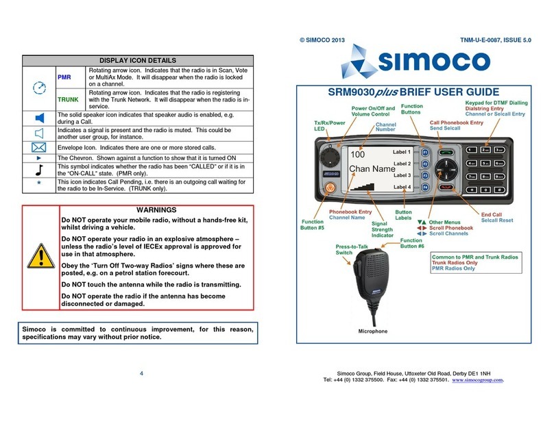
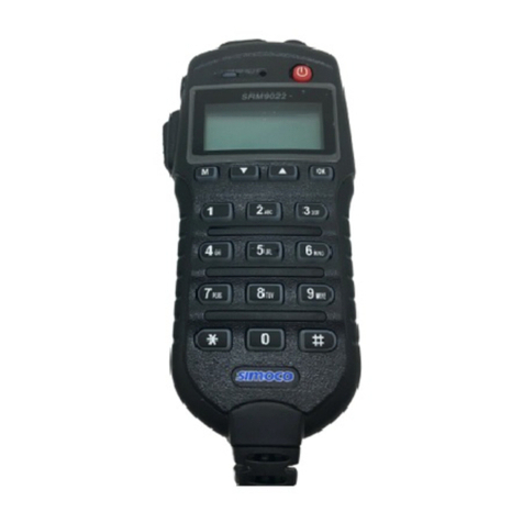
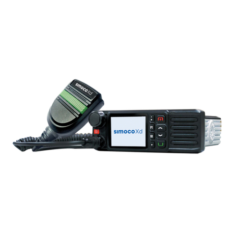
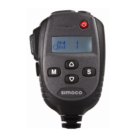
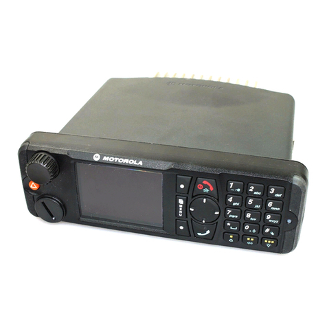
Simoco SRM9000 User manual

MRMap Development Team 14/01/2009
MRMap - www.mrmap.org.uk
MRMap-GPS-Tracking-Communications-Safety-Mountain Rescue-Mapping-Downloads-Free Software
Rebroadcast Manual
Simoco SRM9000-Based Radio Rebroadcast
& Repeater Devices.
Collated By The LDSAMRA Communications Sub Committee
On behalf of the contributing teams of the North West of
England and Southern Scotland.
Rev C 14 January 2009

MRMap Development Team 14/01/2009
As a result of a meeting held at Keswick MRT HQ on 6th September 2005, this document has
been produced in order that information presented at the meeting but considered too detailed
for inclusion in the minutes, might be passed on to all interested parties. It is not pitched at
any presumed level of understanding and some things are explained even though
they may be obvious to all. Conversely, anything that’s not obvious can be ex-
plained in greater detail, by one or more of the contributors.
The sections included have come from the team responsible for developing the device or con-
cept and the author is responsible only for graphics and writing up or collation of the various
documents.
All re-broadcast devices are based upon current Simoco radio equipment and thanks are due
to Team Simoco Ltd in Derby and Huntingdon, and TMC Radio Pty Ltd in Australia for their
help in resolving issues that arose during the construction of these devices.
In the majority of cases, the wiring associated with power supply, speakers and aerial connec-
tions are not shown in order to help with clarity. In the case of speakers, this is a local deci-
sion as to whether they are used. They are not strictly necessary to the functioning of a re-
broadcast or repeater device but one will be required if the ‘Standard’ variation is adopted as
one of the radios forms the normal comms set for the vehicle when it’s not in re-broadcast
mode.
With thanks to :-
Bowland Pennine MRT
Coniston MRT
Duddon & Furness MRT
Kendal MRT
Keswick MRT
Moffatt MRT
Penrith MRT
Roger Taylor, Tower Communications
Team Simoco Ltd
TMC Radio Pty Ltd
Tom Taylor ARCC Kinloss

MRMap Development Team 14/01/2009
Introduction:-
The concept of re-broadcasting:-
The devices to be described are intended to act as two-way signal enhancement units to enable
radio communications into difficult-to-reach areas. To this end, a system using two simplex
transmissions on different frequencies has been adopted where the Base or Incident Command
Post (ICP) transmits and receives on one channel and the Hill-Parties do likewise on their Team
Working Channel (TWC). From this it can be seen that operation at the Hill-Party end remains
simplex for normal comms on the hill. Hand-portables can still speak to each other whilst taking
advantage of the increased area or distance coverage provided by the re-broadcast device.
The device itself is nominally mounted in a vehicle that is dynamically positioned to allow for the
translation of the Base transmission onto the frequency used by the Hill-Party and vice versa.
When using the re-broadcast unit, Base cannot speak directly to the Hill-Party radios. It must go
via the re-broadcast device hence the positioning of this vehicle is critical to operation of the
system as a whole. Having said that, it is strongly recommended that Bases / ICPs do monitor
the TWC as it is then often possible to make direct contact with a party that is not in the cover-
age area of the rebroadcast unit.
As originally agreed in negotiations with OfCom for permission to use such a device, it must be
clearly stated from the outset that permanent operation of re-broadcast transmitters was not
agreed by the authorities. Re-broadcast should be used to alleviate individual communications
problems on a case-by-case basis. When normal methods of communications fail. That is, when
direct communications between the Base/ICP and the deployed Hill-Party hand-portable radios is
not directly possible due to the nature of the immediate terrain and not the terrain in general.
More rebroadcast channels have been requested so that if the topography of any Team’s area
forces continuous use of a re-transmission system then they may deploy a unit on a more per-
manent basis. At the time of update August 2008, no additional link channels have been author-
ised.
We are, however, now authorised for operation of re-broadcast devices from perma-
nent locations.
It is important that this is fully understood by any Team wishing to use re-broadcast as there are
almost certainly going to be incidences of mutual interference between different Teams during
the initial testing phase and, indeed, in their normal operational usage. Any team operating out-
side the conditions of use of re-broadcast devices has no redress if it receives an unacceptable
level of interference. Conversely, any team causing interference to others may well find OfCom
on their doorstep. Always bear in mind that the new ‘MR’ channels are subject to the same level
of official monitoring that is applied to the rest of the marine band.
Rob Brookes/Tom Taylor 14 January 2009

MRMap Development Team 14/01/2009
The General Principles of Rebroadcasting
As you will see in the following pages, re-broadcast is not a lot different in effect, from
manual relay. The same vehicle in the same position could handle both methods. The only
real difference is that there is now no need for the vehicle driver to relay massages to base.
The argument that manual relay takes a team member off the hill is not really valid as most if
not all teams have people who’s hill-going days are a memory rather than a fact. These people
do, however, have a wealth of understanding as to what the rest are doing when dashing up
the hill. They are to be found in the manual relay vehicles of a number of teams already.
Radio re-broadcast does not make them redundant, in fact it may well make their lives a little
more interesting occasionally. For automatic
re-broadcast to work, the vehicle must be correctly positioned. The driver of the manual relay
vehicle may well, during the course of a search for example, have to move the vehicle in order
to maintain good comms between him or herself and base whilst still being able to contact the
moving hill-party. This doesn’t change in re-broadcast and if there is any possibility of the hill-
party shifting it’s position then an un-manned re-bro vehicle may become unusable. Intelligent
autonomy is required from your rebro vehicle driver, they must re-locate to a new position,
sometimes without any instruction from base. They become a very important element of your
communications system as a whole.
The job of the rebro vehicle driver, is to find the best position to establish good comms be-
tween base and the vehicle and the hill-party and the vehicle. Once this has been done, the re-
broadcast device can be switched on and comms is then automatically handled by the vehicle.
However, the driver still needs to monitor the comms to ensure that the vehicle is still in the
optimum position. If not then he or she will have to advise both parties of an intention to re-
locate and this must be done as quickly as possible.
Re-broadcast isn’t magic, it won’t always work. All teams have places where comms are par-
ticularly bad and base will expect to loose the hill-party in such locations. If they’re just passing
through this location, it probably doesn’t matter. If the casualty has managed to crawl to the
most difficult location possible before collapsing then most of your work will occur out of reach
of comms with base. Whether this is important or not depends on a lot of factors but it proba-
bly will be.
This is what the re-broadcast system was designed for as against wide area repeaters de-
signed to provide saturation coverage of a team area. Most Lakes and Lancs teams already
have reasonable coverage of their areas by radio, usually from existing fixed sites. We have all
had radios for over fifteen years so they aught to work by now! They don’t cover everywhere,
indeed, the laws of physics prevent this anyway. However, the positioning of remote aerials or
careful positioning of bases has resulted in generally good coverage. In effect, most teams
unknowingly have a simplex version of ‘Wide-area-coverage’ already.
MRMap Development Team 14/01/2009
What re-broadcast does is to fill in the gaps on those occasions when the main system
struggles to cope. You wheel it out in just the same way you would your manual relay vehicle.
Under some circumstances, it doesn’t even have to be a full-blown team vehicle anyway.
These devices can be fitted to virtually anything that can provide them with power as Penrith
and Bowland Pennine have both shown. Now we have it where the re-bro vehicle is not taking
out an active hill-going member of the team, nor is it necessarily tying up a team vehicle. If
the private vehicle doesn’t have a pump-up mast fitted, and how many do? Arrange with a
local farmer who lives at a well-used relay location, to put a mast on his barn and plug your
radios into it when you need them. There are always ways.
The job of the vehicle driver now becomes more critical as base can quite easily tell when a hill
-party are moving out of comms range but they will find it hard to predict just where the relay
vehicle needs to move to. That’s a job best left to the man on the ground, the driver. Relay
vehicle driver is a job probably not best left to the newest team member.
If the driver uses a handset that has been arranged to scan between the team working
channel and the rebro channel, then he or she will be able to hear both sides of the
conversation, provided by the rebro they’re operating. By the same token, the driver can also
speak to either side of the rebro by using the opposite channel on the handset. They can
become either base or hill-party depending on which it is they need to speak to.
Indeed, program the two channels to say who it is you will be speaking to and it’s even easier.
Program the radio’s display to read ‘Hill-Party’ and program the frequency as 147.350 MHz and
the driver will become base for the time being. The transmissions will be boosted by the re-
bro. If this is used then the handset’s power need only be a watt or less and the battery will
last forever.
By the same token, program the display to say ‘Base’ and the channel as your TWC and the
driver becomes another hill-party radio and will be heard by base via the re-bro. In neither
case does the driver’s radio need to be able to transmit back to either side un-aided. It uses
the re-bro in just the same way all others do.
The driver can now leave the vehicle temporarily without being out of comms with either hill or
base.
Sometimes the urgency of a message can be lost when it’s passed by another’s voice. Using re
-broadcast, the margin for translation errors when passing messages is dramatically reduced
as no intermediary has to repeat them with all the inherent dangers of accidental
interpretation or inflection changes.
The intention isn’t that they are used routinely to provide base to hill communications although
the position of your team base has a lot to do with this and, for example, Duddon & Furness
have a base location not well suited to covering their whole area. Their deployment of
re-broadcast vehicles will be more than most. It’s not in the interests of avoiding interference
for us all to operate in this way but one or two aren’t going to cause too many problems if
those who don’t need to deploy them regularly, keep to that principle.

1
Direct communications from the base, May not be
possible with the party on the opposite side of the
hill. The signal from base will just pass over their
heads or be absorbed by the intervening hills. In the same way, the hill-
party cannot make contact
with the base.
Base could transmit to the vehicle and ask it to relay out to the
hill-party as we have always done in the past. The vehicle needs
to be manned and in the right place!
General Principles - The Old Way—Manual Relay from a vehicle
Manual Relay Vehicle
!*^$*!
Radios
Base
1
2
3

2
You could park a vehicle as high as you can get it but this is bad for relations with the neighbours and bad for the level of interference you will receive your-
selves from teams in other regions who are probably operating correctly so you have no re-dress. At least one police force, Derbyshire, is actually still using
the re-bro channel so you will definitely attract some attention by using the illustrated approach!
General Principles - Not in the spirit of the thing!

3
Using the re-broadcast device, the base changes to
channel 96 (147.350 MHz). It both transmits and
receives on this channel.
At the vehicle, the signal received from the base is converted to the Team Working Channel.
It is then re-broadcast out to the hill-party. The positioning of this vehicle is critical to correct operation of the system. The vehicle must be able to ‘see’
both stations trying to communicate with each other however, it doesn’t always need to be manned.
147.350 MHz
both ways
Team Working
Channel both ways
For re-broadcast to work successfully, it isn’t necessary
to take the vehicle to the top of any hills. It only needs to
be in a position where both the base and the hill-party
can be satisfactorily contacted from the vehicle.
Simplex comms between handsets
on the hill
Re-Broadcast Vehicle
General Principles - The New Way—Automatic re-broadcast from a vehicle
Base
1
2
3

4
Optimum Position Planning.
It’s possible with a little work, to pre-plan suitable locations for known radio black-spots. The free, on-line coverage calculator provided by
ATDI can give a coarse prediction of coverage for a given location. In the example below, a location at a view-point on the A684 Garsdale
Road gives an indication that it would permit re-broadcast from the Kendal remote site at Singleton Park, out to the Cautley Spout area where
comms are otherwise impossible.
Although this hasn’t been checked, it
does give some indication (for free) of
where we might want to begin looking
for a suitable location when working in
the Cautley area.

5
Radio Mobile software is a copyright of Roger Coudé VE2DBE. Radio Mobile is dedicated to amateur radio and humanitarian use. Although commercial use is not prohibited, the author cannot be
held responsible for its usage. The outputs resulting from the program are under the entire responsibility of the user, and the user should conform to restrictions from external data sources.
The official Radio Mobile web page is http://www.cplus.org/rmw/english1.html
Radio Mobile software is free but you can help...
By using the FreeWare ‘RadioMobile’ application, much greater accuracy can be achieved when plotting optimum coverage of fixed or mobile sites.

6
First Steps - The Simple Approach to Rebroadcasting.
The following information is based upon documentation published on the TMC Radio website and
research carried out by various teams.
It represents variations on broadly similar systems that increase in complexity as they go on.
Ideally a team radio officer would select the version he or she feels is most appropriate for their
own team. All the following examples work but there are explained reasons why some of the
very simple versions would not be completely practical.

7
The various radio configurations used to form
rebroadcast devices are taken from information
provided by TMC Radio Pty Ltd in Australia.
They are the manufacturers of the ‘Simoco
SRM9000’ series radios. Rebroadcast can be
achieved using other manufacturers hardware
but the extremely simple way in which this is
achieved with SRM9000’s, and the number of
variations available for experimentation, means
they are hard to beat under these circum-
stances.
All re-broadcast units require two radios.
One on the team working channel (TWC) and another
On the re-broadcast channel shown here as a
hypothetical Low Band (68 to 88 MHz) channel
TWC Low Band
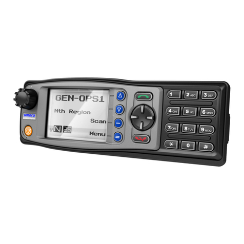
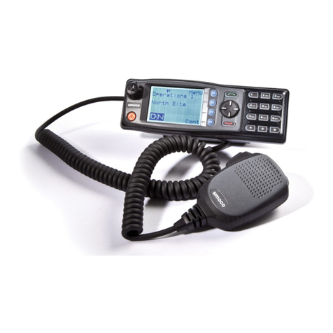
The two SRM9005’s require only a special cross-linking cable connected between the front-mounted RJ45 jack sockets, in order to be-
come a rebroadcast device. The rebroadcast mode is automatically selected once the cable is fitted and both radios are switched on. See
the next page for details of the cable.
This is fundamentally the same for all variations on the system. Two radios connected by a crossover cable.
Using the configuration shown, the Team Working Channel (156.175 to 161.875 MHz) is converted and simultaneously re-transmitted on a suitable low band
frequency. 86.3125 MHz for example as is used in Scotland. Whatever the frequencies used, the system adopted is called ‘Two-Frequency-Simplex’ . That
is, two separate frequencies are used in the system, one in the primary radio and another in the secondary radio. Each radio both receives and transmits on
it’s programmed frequency hence is simplex in operation. All persons listening to either of the two radios will hear both sides of the conversation and each
other. The rebroadcast device converts one frequency to the other and re-transmits it.
The above circuit is the simplest form of this device and requires no other hardware apart from power and aerials. The operating channel of the TWC radio
can be changed but this requires that a 9025 telephone handset or a similar control head, is plugged into the socket occupied by the cross-over cable so is
obviously not a permanent feature. Basically, this device is meant to operate on one TWC only.
The Simoco 9025 telephone handset control head
and magnetic mounting plate
Very Basic Rebroadcast
There are no UKSAR low band channels available but a number of teams have now pur-
chased their own frequencies from Ofcom for this purpose and under these circum-
stances, this is a viable solution to the problem.
“Cross-Band” Re-Broadcast.
Defined as :- Each radio operates in a different part of the radio spectrum, here, high band and low band. They therefore don’t interfere with each other.

8
Cross-Linked Cable (Part Number : 9503-000-00018)
The cross-linked cable simply swaps the Tx/Rx Data lines (enabling the two Transceivers to communicate), and cross-connects the Receive and
Mic Audio lines so that the audio signals can pass between the Transceivers. You can easily make one up by splitting a short CAT5 patch cable
and re-jigging the connections.
Editor’s note:- Pin 5 on both RJ45’s is left un-connected. I believe this is not the case on the crossover lead supplied to LDSAMRA.
This diagram shows the pin-out and part number of the Crossover lead. It can be made up to virtually any length using standard CAT5 components.
From Simoco, the cost is about £12. All SRM9000-based versions of the re-broadcast device require this cable to be fitted.
Note that the two radios are placed into rebroadcast mode as soon as the crossover cable is connected.
Information taken from TMC publication - A9k-501 “Simple Repeater” available from the TMC Radio website at www.tmcradio.com

9
The current sinking capacity of pin 8 is
around 130mA so the combined current re-
quired to switch any external devices, should
not exceed this. This can be increased using
transistor switching if necessary.
Back of the power plug
The Standard Power and
Speaker Connector (Facility con-
nector)
Four pins linked for negative supply lines
Four pins linked for the positive supply
Pin 3 - the Ignition sense connection. Pin 3 should be linked
to the adjacent positive supply pins to ensure switch-on.
Pin 8 - the programmable output
connection. (Programmed to be
Low on Tx)
The SRM9000 power and facility connector.
Speaker connections - pins 6 and 13
NO7BB 12 volt LED Green
NO5BB 12 volt LED Red
Maplin Electronics
Simple System
On/Off Indication
Where no control head is used, as in the ‘Simple’ repeater…….

10
The TMC Radio ‘Simple’ Repeater
This is the simplest form of rebroadcast/repeater possible using Simoco SRM9005 radios.
Normally no speakers would be connected and there is no control head.
Because both radios operate on frequencies that are not too far apart, some interference
between the two is to be expected. Adequate vertical separation of the antenna can help here.
Horizontal aerial separation is unlikely to prove effective unless your base is in the grounds of a
medium size castle.
You are recommended to visit the TMC Radio website and to download the file A9k-501 ‘Simple Repeater’.
www.tmcradio.com

11
TWC 147.350 MHz
If the currently designated VHF rebroadcast channel of 147.350 MHz is to be used instead of a low band channel, then the risk of mutual interference
between the two radios is high.
This system has been made to work by introducing a degree of vertical separation between the aerials of each radio. Say one on the vehicle roof, and the
other at the top of a suitable mast. Over limited distances it does work and allows all Team Working Channels to be used. Again, channel changing is
effected by temporarily replacing the crossover lead with a control head in the TWC radio.
This is still not a fully practical solution but it does work. Being in the same band, the radios will tend to interfere with each other.
This aerial significantly higher
than the other.
Crossover lead
The High Band Rebroadcast Channels
and Vertical Aerial Separation.
“In-Band” Rebroadcast.
Defined as :- Both radios are in the same radio frequency band.
In this case, both are high band.

12
Very roughly the Diplexer works as follows;
In order that the in-band radios can operate side by side without de-sensing each other, a device called a diplexer (or duplexer) can be used. This is basi-
cally two independent filters. One is tuned to the frequency of one radio and the other to the frequency of the second radio. Diplexers are not required when
cross-band re-broadcast is used.
In the present case, one side is always tuned to 147.350 MHz as this is the common uplink channel used by all of us at this time. This is the ‘Low’ side
of the diplexer. The other radio would be programmed with your Team Working Channel, the ‘High’ side. In practice, this works a little like the left and right
channels on a stereo amplifier. The two radio frequencies are kept apart and not allowed to interfere with each other. The price you pay for this is that the
tuning of the diplexer is both precise and narrow. If it were not then they wouldn’t work!
On the 147.350 MHz side, this isn’t a problem as only this channel is required, but on the TWC side, ideally we would like to be able to use the rebroadcast
on all TWC’s. Sadly, due to the narrow tuning, this isn’t possible and the best we can achieve is that if your TWC is an ‘A’ channel as in 63a or 156.175 MHz,
then you can use your re-broadcast device on any other ‘A’ channel. The same goes for the ‘B’ channels as in 85b or 161.875 MHz. These teams can have
their rebro operate on any ‘B’ channel. When operated away from the channel for which it’s been tuned, the diplexer will degrade the performance of the
radios.
The only channel available to both types of rebro is 158.650 MHz or 53a. This is approximately mid-way between both sets of channels and would be avail-
able as a common channel should this ever be needed. It’s still not ideal and the performance of your system will inevitably be degraded.
Simultaneous receive and
transmit From a single
aerial. The Diplexer
effectively ‘steers’ each
frequency to the correct
radio
Filter tuned to
the TWC Aerial socket of
the TWC radio
Filter tuned to
147.350 MHz Aerial socket of
the 147.350 MHz
radio
Electrical screening between the
two sets of coils

13
A simple rebroadcast device capable of operating on your own Team Working Channel and a few others near to you would be built like this.
This is the ‘Simple Repeater’ as described in the TMC Radio publication A9k-501. The only difference is the addition of the diplexer allowing use of frequen-
cies, in both radios, that are close to each other.
De-sensing is reduced to a very low level and only a single aerial is required. How-
ever, changing channels is no easier with this device than with any others so far
described. A control head is still required. For single channel working, ie on a team
TWC only, this configuration is all you will need.
TWC
147.350 MHz
The radio frequency signals
are ‘steered’ to the correct
radio by the tuning coils.
Diplexer
Crossover cable
The ‘Simple’ In-vehicle, Re-broadcast Device.
A practical, if basic, solution. In a vehicle, a separate radio would be used for normal voice comms. The above
device is only switched on when rebroadcast is needed as shown in the next section.

14
The TMC Radio ‘Simplest’ Repeater
This is probably the method that most teams initially looked at and the one several teams now
use. It works fine with a little training and it’s only real fault is the need for three radios and two
aerials for each vehicle. Having said that, it’s a very flexible and reliable method of setting up a
vehicle rebroadcast system and some teams may need to go no further than this.
To run the system efficiently, you do need to have the facility to switch off the pair of radios
making up the rebroadcast section. They really only need to be powered up when the
rebroadcast is in use.

15
The TMC Radio “Simple Repeater” The full, in-vehicle, configuration.
The ‘Practical “Simple” Repeater’ is probably the easiest to set up and get going. It can’t however, manage the normal vehicle communications task
because it has no control head. This has to be carried out using a third radio dedicated to providing normal comms. This radio is fitted with a control head
and would be at the front of the vehicle. When using this radio, the rebroadcast radios should be switched off and when using the re-broadcast, the main
vehicle radio should be switched off.
TWC147.350MHz
Secondary Rebroadcast
Radio Primary Rebroadcast
Radio
Control of rebroadcast
depends on which radios
are switched on.
Using the above switch
suggestion, only one
setup can be on at any
time. Either the main
radio or the Rebro can
be on, never both.
Diplexer
Independent Vehicle
Communications Radio
Two independent aerials are required. Positive battery supply
Power to the Main Vehicle radio
Power to the Rebroadcast radios
Crossover cable
Using a dash-mounted rocker switch to provide power to either
system but not both.
This approach is only partially successful for a number of reasons, the main one being
that it requires three SRM9000’s to make up the complete communications system for a
rebroadcast vehicle. Some teams may accept this in view of the ease with which the
system can be set up. It will certainly work as a rebroadcast device.
Other manuals for SRM9000
2
Table of contents
Other Simoco Radio manuals

Simoco
Simoco SDM730 User manual

Simoco
Simoco SDM630 User manual

Simoco
Simoco P25 SRM9022 User manual

Simoco
Simoco SRM9020PLUS User manual

Simoco
Simoco SDM600 Series User manual

Simoco
Simoco SDM610 User manual

Simoco
Simoco SRM9030 User manual

Simoco
Simoco SRM9022 User manual

Simoco
Simoco P25 SRM9030 User manual

Simoco
Simoco P25 SRM9022 User manual