Stratus SAE-C10C Guide

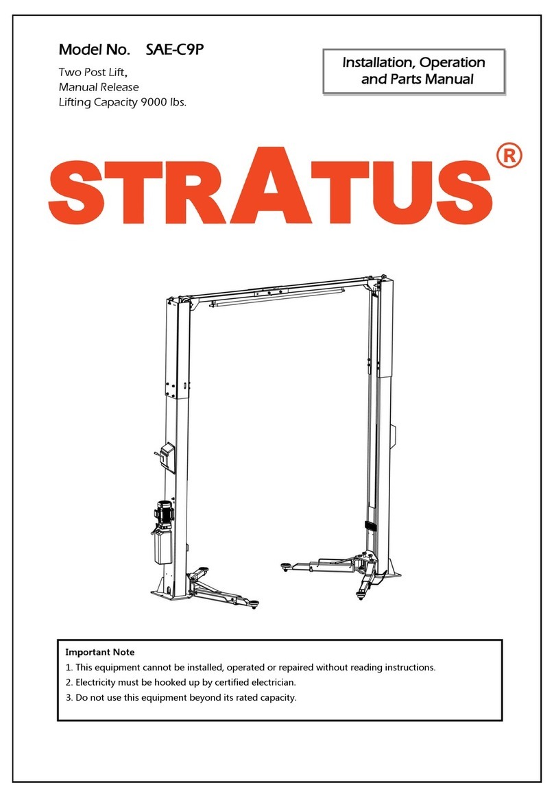
Stratus 2 Post Overhead Li Installaon & Operaon & Maintenance Instrucons
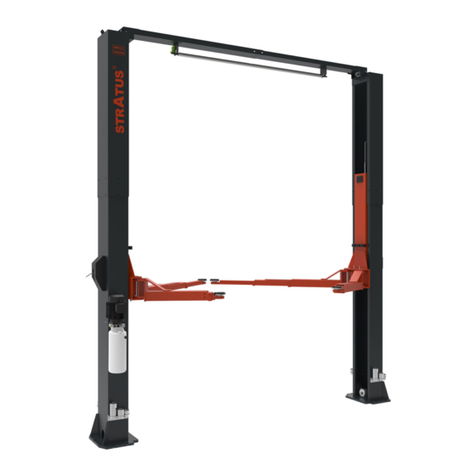
Model No.: SAE-C10C
2 Post Overhead Li
Sing (1) Point Manual Release
Liing Capacity:10000LBS
Installaon & Operaon
Maintenance & Instrucons
Important Note
1.This equipment can not be installed, operated or repaired without reading instrucons.
2.Electricy must be hooked up by cered electrician.
3.Do not use this equipment beyond its rated capacity.

2
Directory
1-The amin features of the equipment ……………………………………………………………………………………4
1.1-Product descripon……………………………………………………………………………………………………4
1.2-Features of the product ………………………………………………………………………………………………4
1.3-Satey mark of the product ……………………………………………………………………………………………4
2-Technical Date of the equipment ………………………………………………………………………………………5
2.1-Product Dimensions …………………………………………………………………………………………………6
2.2-Tools required…………………………………………………………………………………………………………7
3-Installaon ………………………………………………………………………………………………………………8
3.1-Preparaon ……………………………………………………………………………………………………………8
3.2-Foundaon requirements……………………………………………………………………………………………8
3.3-Installaon steps ……………………………………………………………………………………………………10
4-Equipment Installaon …………………………………………………………………………………………………13
4.1-Assemble Columns …………………………………………………………………………………………………13
4.2-Assemble overhead top beam ………………………………………………………………………………………13
4.3-Posion Columns ……………………………………………………………………………………………………16
4.4-Install overhead top beam……………………………………………………………………………………………16
4.5-Adjust Carriage………………………………………………………………………………………………………17
4.6-Install Equalized Cables (2 Cables in total) …………………………………………………………………………17
4.7-Install Hydraulic Hose (2 Hose in total) ……………………………………………………………………………18
4.8-Install Safety Lock Release Cable……………………………………………………………………………………19
4.9-Install Power Unit……………………………………………………………………………………………………19
4.10-Safety Lock Release Cable & Hose & Top Limiter Switch Wire Protecon cover…………………………………20
4.11-Install Anchor Bolt…………………………………………………………………………………………………22
4.12-Install Arms and Pulling Rod………………………………………………………………………………………22
5-Check Before Start………………………………………………………………………………………………………23
5.1-Mechanical Installaon Check………………………………………………………………………………………23
5.2-Electrical Hook Up Check……………………………………………………………………………………………23
5.3-Hydraulic System Tesng ……………………………………………………………………………………………24
5.4-Load Test ……………………………………………………………………………………………………………24

3
6-Operaon and Use……………………………………………………………………………………………………25
6.1-Operaon …………………………………………………………………………………………………………25
6.2-Raising/Liing………………………………………………………………………………………………………25
6.3-Stopping ……………………………………………………………………………………………………………25
6.4-Lowering ……………………………………………………………………………………………………………25
7-Safety …………………………………………………………………………………………………………………25
7.1-Important Reminder………………………………………………………………………………………………25
7.2-Vehicle Posion……………………………………………………………………………………………………26
7.3-Risk of Vehicle Falling O form the li……………………………………………………………………………26
8-Maintenance …………………………………………………………………………………………………………26
8.1-Every Month Hydraulic System……………………………………………………………………………………26
8.2-Every 3 Month Safety Maintenance………………………………………………………………………………26
8.3-Every 6 Month Hydraulic Pump……………………………………………………………………………………27
8.4-Every 12 Month……………………………………………………………………………………………………27
8.5-Regular Lubricaon…………………………………………………………………………………………………27
9-Troubleshoong Guide………………………………………………………………………………………………28
10-Structure and Parts List……………………………………………………………………………………………29
10.1-Main column………………………………………………………………………………………………………29
10.2-Vice column………………………………………………………………………………………………………30
10.3-Carriage Assembly…………………………………………………………………………………………………31
10.4-Overhead Crossbeam Installaon………………………………………………………………………………32
10.5-Main column safety lock assembly………………………………………………………………………………33
10.6-Slave column safety lock assembly………………………………………………………………………………34
10.7-Two stage arm assembly…………………………………………………………………………………………35
10.8-Three stage arm assembly………………………………………………………………………………………35

4
1-The main features of the equipment
1.1-Product descripon
This product is a hydraulic li. The product is manual single point lock release, easy to operate. It is suitable for
inspecon, repair and maintenance of a vehicles below 10000lbs.
1.2-Features of the product
When the power unit of the hydraulic li is connected to the power supply, press the switch, the gear pump works,
and the hydraulic oil pushes the piston rod up, which is brought to the pulley and the pulley and the safety lock
tooth will blink and bite each other during each ascent. At the same me, to ensure that the hydraulic system will
not cause slippage.
1.3-Satey mark of the product
Do not come under the vehicle during
operaon. This can cause injury and
death.
Evacuate to a safe place instantly the
event that the vehicle ps. This can cause
injury or death.
Before lowering the li, check that
there are no obstrucons under the
vehicle or the li arms.
Do not operate damaged equipment.
When the vehicle is lied, do not rock
it as this may dislodge it.
Only trained person may operate the
equipment. Inexperience can cause acci-
dents.
Do not li a vehicle using on pair of
arms only.
Do not operate the push buon except
the worker.
Do not rock the vehicle when lied. Do
not use a high pressure cleaner to the
vehicle lower part.
To avoid being electrocuted, disconnected
the main power before opening the con-
trol panel.
To avoid injury, keep your feet clear of
the arms and carriages.
Read and fully understand the manual
before using the li.
Not allowed unauthorized persons in
the work area.
Before going under the li. Make sure that
the safety pawls are engaged.
Posion vehicle with center of gravity
midway between adapters.
Make sure that the front and back balance
when placing the car, otherwise the car
will fall.
Do not modify the control panel or the
safety funcons as this may impair
their funcon.

5
Model SAE-C10C
Symmetric Installaon Asymmetric Installaon
Liing capacity 10000lbs/4500kg 10000lbs/4500kg
Liing height 74 13/16″/1900mm 74 13/16″/1900mm
Min. height 3 15/16″/100mm 3 15/16″/100mm
Column inside 118 3/16″/3002mm 110 5/8″/2810mm
Drive through 106″/2693mm 101″/2565mm
Liing me About 50 sec. About 50 sec.
Lowering Time About 40 sec. About 40 sec.
Column thickness of steel 1/4″/5.5mm 1/4″/5.5mm
Carriage thickness of steel 1/4″/5.5mm 1/4″/5.5mm
Arms thickness of steel 1/4″/6mm 1/4″/6mm
Arm range 26 3/4″-48 7/16″;34 5/8″-56 11/16″;
680-1230mm/880-1440mm
26 3/4″-48 7/16″;34 5/8″-56 11/16″;
680-1230mm/880-1440mm
Diameter of cable 3/8″/Φ9mm 3/8″/Φ9mm
Voltage 220V 220V
Power 2.2Kw 2.2Kw
Frequency 60Hz 60Hz
Phase 1Ph 1Ph
Breaker 30A 30A
Hydraulic oil AW46/AW32 AW46/AW32
Shipping size 114″×30″×32″;2880×740×810mm 114″×30″×32″;2880×740×810mm
Equipment weight 1440lbs/654kg 1440lbs/654kg
2-Technical Date of the equipment

6
2.1-Product Dimensions
Symmetric Installaon
Asymmetric Installaon

7
2.2-Tools required
Hamer, Socket Wrench Set, Hex Wrench Set, Adjustable Wrench, Screwdriver, Measuring Tape(16’+),Long-Nose Pli-
er, Circlip Pliers, Electric Rotary Hammer, Drill (3/4″), Safety Glasses, Work Gloves, Safety Helmet, Forkli/Crane or
something similar.
Name Picture
Rotary hammer drill (Φ19)
Carpenter’s chalk
Hammer
Screw sets
Level bar
Tap measure
English spanner (12″)
Pliers
Ratchet spanner with socket (28#)
Socket head wrench (3#,5#,8#)
Lock wrench
Wrench set (10#,13#,14#,15#,17#,19#,24#,27#,30#)

8
3-Installaon
This 2 Post Overhead Li is the most common equipment for repairing cars. Its installaon is not only related to the
maintenance eciency but also to personal safety of the maintenance technicians. Therefore, the installaon must
be completed by cered installers according to the User Manual, and in accordance with installaon regulaons.
Recommend to use manufacturer supplied anchor bolts.
Warning: This equipment has 2 installaon methods, which is symmetrical installaon and asymmetric installaon.
No maer which installaon method is selected, all installaon processes including foundaon, beam, column, and
cable xing methods must refer to the corresponding installaon method. Failure to do so may result in equipment
being unusable or damaged.
3.1-Preparaon
3.2-Foundaon requirements
Specicaon of concrete must be adhered to the specicaon as following. Failure to do so may result in li and or
vehicle falling.
◇Concrete must be thickness 200mm minimum and without reinforcing steel bars, and must be completely dry
before li installaon.
◇Concrete must be in good condion and must be of test strength 3000PSI (211kg/cm²)minimum.
◇Floor must be level with no cracks or holes.
Warning: The size and concrete parameters of the foundaon are the minimum strength and foundaon depth pa-
rameters of the installaon. The user needs to adjust the thickness and oor space of the foundaon according to the
maximum weight. It can also be done at the dealer’s suggeson.
Steps of installaon
◇Locaon of installaon
Check and insure the installaon locaon (concrete, layout, space size etc.) is suitable for li installaon.
◇Use a carpenter’s chalk line to establish installaon layout of base plate.

9

10
3.3-Installaon steps
Step 1:Check the pats before assembly.
Packaged li and hydraulic power unit.
Step 2:Move aside the parts and check the parts according to the shipment parts list.

11
Step 3:Spare parts in the accessories box.
Serial
number Name Photo Parameter Quanty
1Arm sha Φ40×168mm 4
2Arm sha elasc cylindrical pin Φ6×50mm 4
3Heightening bracket 2
4Heightening sleeve bracket xing screw Socket head cap screws M8×10 4
5Increased set 1 Φ50×45L 4
6Increased set 2 Φ50×70L 4
7An-collision tape 2
8An-collision tape strip xing screws Socket head cap screws M8×30 4
9Expansion screw M20×160L 10
10 Plasc gasket 15
11 Power unit backpack 1
12 Power unit backpack xing screws Socket head cap screws M10×16 2
13 Power unit xing screws Hexagon Screw M8×25L Each 4
14 Manual unlocking lever M10 Each 1
15 Unlock the wire rope 1
16 Wire rope U-shaped chuck M3 2
17 Brake wire plate for xed brake wire Each 4

12
Serial
number Name Photo Parameter Quanty
18 Plasc cable e 15
19 Main column upper limit switch 1
20 Main column upper limit switch xing screw Phillips round head screws M5×10L 2
21 Upper limit plate and limit switch M4×10 and M4×25 1
22 Upper limit board 1
23 Upper limit plate xing screw Hexagon Screw M10×20L Each 4
24 Two cross arm connecng screws Hexagon Screw M8×20L Each 6
25 Two-secon cross arm end xing screws Hexagon Screw M10×25L Each 8
26 Heightening secon and column connecng
screw Hexagon socket screws M10×16L Each 12
27 Heightening secon buckle cover xing screw Phillips round head screws M6×10L Each 12
28 Cross beam connecng plate xing screw Hexagon socket screws M10×20L Each 8
29 Block rubber cover 2
30 Locking and unlocking rope seat assembly
accessories 2
31 Plasc buckle cover xing screw Phillips round head screws M6×8L 8
32 User’s manual 1

13
4-Equipment Installaon
4.1-Assemble Columns
Assemble main column & extension column, and then stand up the 2 columns (the column with the power unit base
plate is the main column and other one is the vice column). (FIG 3)
Note: Don’t drill anchor bolts holes or install anchor bolts now.
FIG 3 Assemble Columns
4.2-Assemble overhead top beam (FIG 4)
4.2.1-Assemble overhead top beam
Note: The bolts run from inside of the column and then fasten the nuts from outside of the column.
FIG 4 Assemble overhead top beam

14
4.2.2-Install the overhead beam cable pulley (FIG 5)
Warning: Symmetrical installaon and asymmetrical installaon of the cable pulley posions are not universal. In-
correct installaon of the pulley posions may cause damage to the cable or the li.
◇For symmetrical installaon, (pre-installed).
Symmetric Installaon
◇For asymmetric installaon, (pre-installed).
Asymmetric Installaon
FIG 5 Cable Pulley Installaon Reference
◇Mounng posion of cable pulley (FIG 6)
Note: During the installaon, the posions of the cable pulley at both ends of the overhead beam should be in-
stalled correspondingly. There may be a gap between the cable pulley and the sha sleeve, this is for the cable can
be automacally aligned, normal abrasion, Do not add shim to x the posion of pulley, it may cause abnormal
wear of the li.
FIG 6 Cable Pulley Posion

15
4.3-Posion Columns
Check if the column are vercal to the ground with level, insert thin shims (come with package) to adjust when nec-
essary.
◇Symmetric Installaon (FIG 7)
◇Asymmetric Installaon (FIG 8)
FIG 7 Symmetric installaon posion columns
FIG 8 Asymmetric installaon posion columns

16
4.4-Install overhead top beam
◇When symmetrical installaon method is adopted, cable pulley (refer to FIG 6)should be installed according in
a symmetrical manner and x the 6 screws underneath the overhead beam (FIG 9).
◇When asymmetrical installaon is adopted, cable pulley (refer to FIG 6) should be installed according in asym-
metrical manner and x the 5 screws underneath the overhead beam (FIG 10).
FIG 9 Symmetric Install overhead top beam
FIG 10 Asymmetric Install overhead top beam

17
4.5-Adjust Carriage
Raise the carriage to the 1st locking posion located at the boom of the column (FIG 11).
Note: You can hear “click” once locked (the 1st locking posion) is about 11.8″ from the ground).
FIG 11 Carriage Posion
4.6-Install Equalized Cables (2 Cables in total)
Note: Please pay aenon to the change of the hanging point of the cable during symmetrical installaon (FIG 12)
and asymmetrical installaon (FIG 13) during the installaon.
FIG 12 Symmetric Installaon Cable Roung Diagram

18
FIG 13 Asymmetric Installaon Cable Roung Diagram
4.7-Install Hydraulic Hose (2 Hose in total)
Connect the longer hose in between the 2 cylinders, connect the short hose in between the cylinder and the power
unit. Please hand ghten to avoid thread damage, then use hand wrench to fasten completely.(FIG14)
FIG 14 Hydraulic Hose Diagram

19
4.8-Install Safety Lock Release Cable
◇The safety lock has been pre-installed.
◇Install safety lock release cable to connect the safety lock on the main column and vice column. (FIG 15)
◇Install safety lock cover.
NOTE: Press the single point lock release lever on the main column to check if this lever can release the mechanisms
in both columns at the same me. Adjust the safety lock release cable adjustment screw if necessary unl the lever
can release the mechanisms in both columns at the same me.
FIG 15 Safety lock release cable installaon diagram
4.9-Install Power Unit
Install power unit & motor mounng plate on the main column with M8 screws (FIG 16).
FIG 16 Power Unit Installaon Diagram

20
4.10-Safety Lock Release Cable & Hose & Top Limiter Switch Wire Protecon cover.
◇Safety Lock Release Cable & Hose & Top Limiter Switch Posion (FIG 17& FIG 18).
Not: Don’t across safety lock release cable & Hose & Top Limiter Switch Wire.
FIG 17 Symmetric Installaon
Safety Lock Release Cable & Top Limiter Switch Wire Posion
FIG 18 Asymmetric Installaon
Safety Lock Release Cable & Top Limiter Switch Wire Posion
◇Install protecon cover (FIG 19)
Note: The protecon cover on the extension column for safety lock release cable & hose & top limiter switch has
already welded on, and you only need to install the protecon cover on the main column.
Table of contents
Other Stratus Lifting System manuals

Stratus
Stratus SAE-C10P Guide
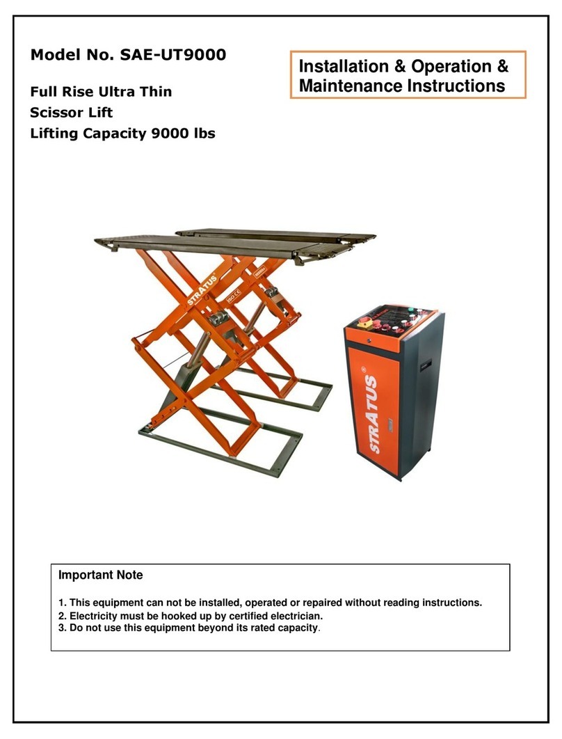
Stratus
Stratus SAE-UT9000 Guide
Stratus
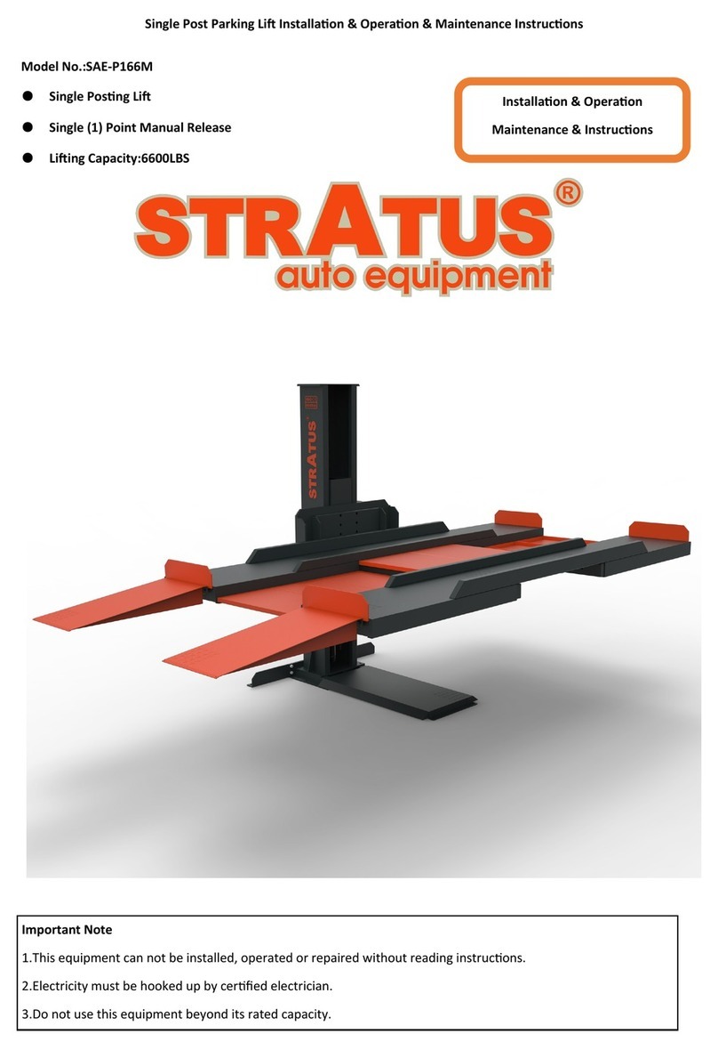
Stratus SAE-P166M Guide
Stratus
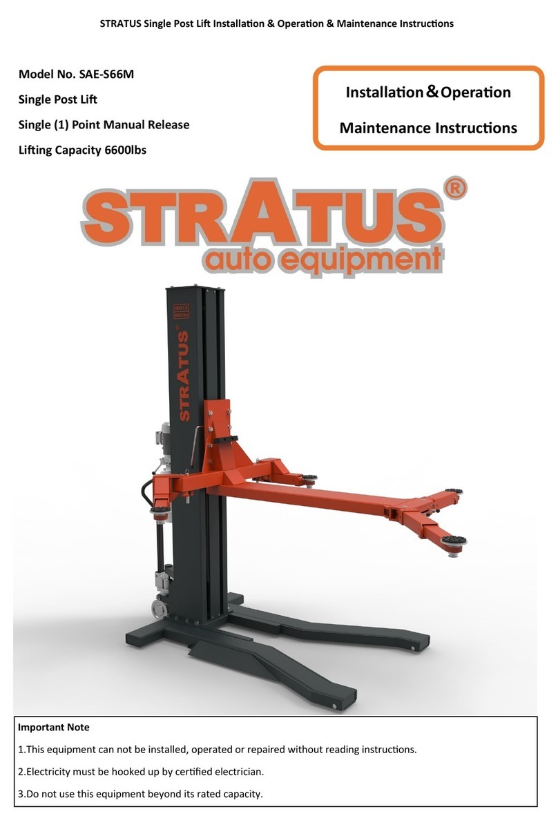
Stratus SAE-S66M User manual

Stratus
Stratus SAE-P410 User manual
Stratus
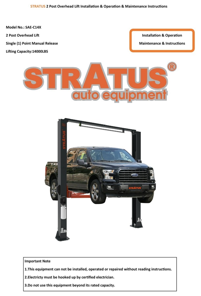
Stratus SAE-C14X Guide
Stratus
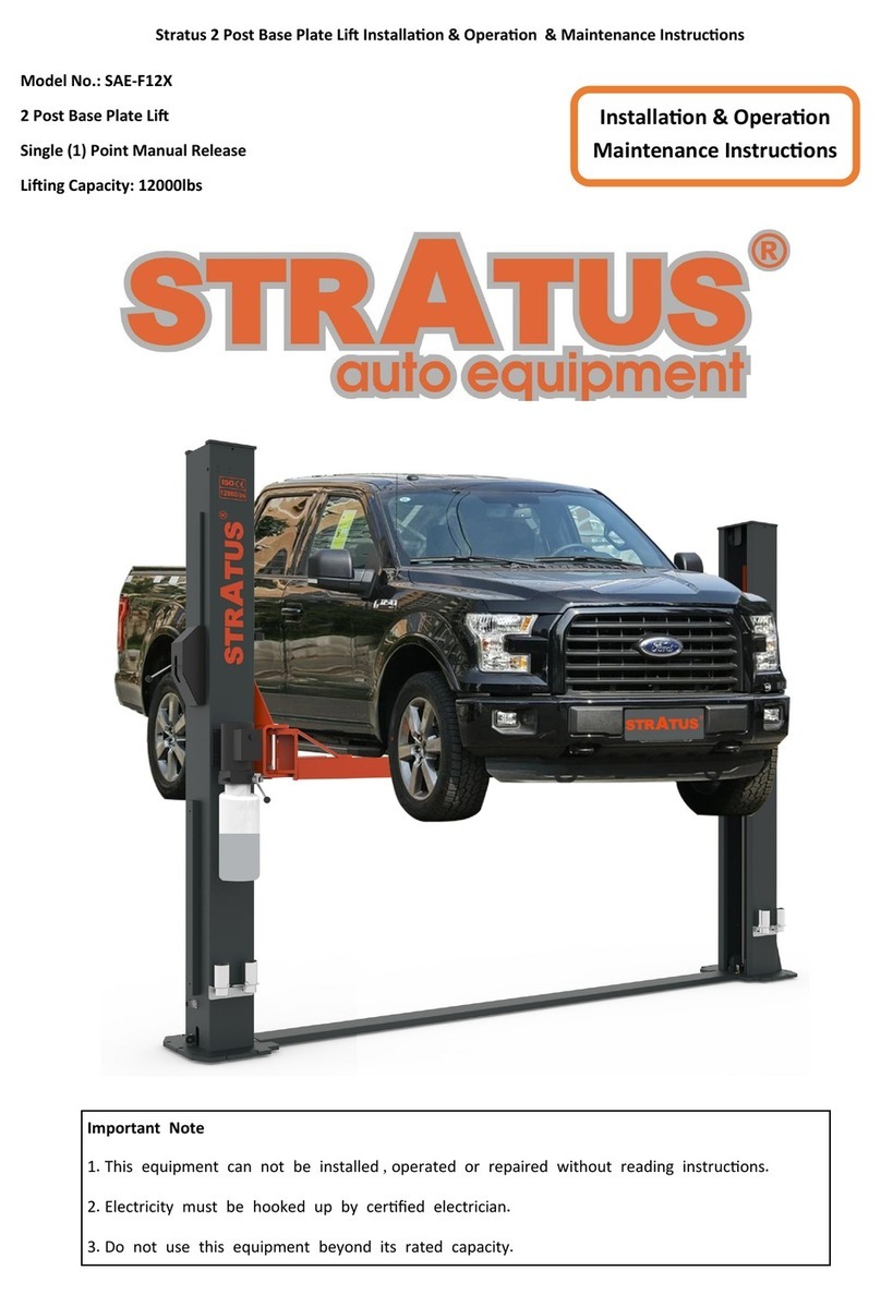
Stratus SAE-F12X Guide
Stratus
Stratus SAE-F10P Guide
Stratus
Stratus SAE-P48 Guide
Stratus
Stratus SAE-F14X Guide

