1
FormA900
Date3-02/A
Page 1 of 4
Printed In U.S.A.
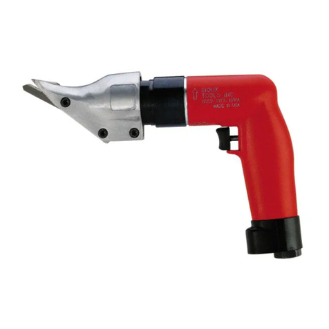
INSTRUCTIONS & PARTS LIST
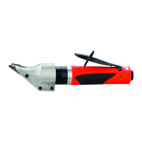
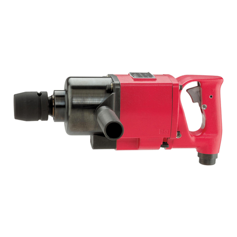
FOR1446HPLAIRSHEAR
AIRSUPPLY
Theefficiencyandlifeofthistooldependsonthepropersupplyof
clean,dry,lubricatedairatabout90Ibs.P.S.I.,althoughhigheror
lower pressures may be used. The use of an air line filter,
pressureregulatorandlubricatorisrecommended.
Beforeconnectingthetool,blowtheairlinetoremovewaterand
dirtwhich may haveaccumulated. This isespecially important for
a new line or when the line has not been used for some time.
HOSEANDHOSECONNECTION
Theair supply hoseis 3/8" I.D.If extension hoseis necessary,
use1/2" hose, withcouplings not lessthan 3/8" I.D.
LUBRICATION
Anoilsupplytothe air motor isimportant.SIOUXairlinelubrica-
torsarerecommended.Adjust to deliver2dropsofSIOUXAir
MotorOilNo.288 per minute. Whenairlinelubricatoris not used
squirtseveraldrops of oil intotheair inlet before using.Gearcase
andShearheadmust be lubricated afterevery40hours of
operationwithSIOUXGreaseNo.289A.
SAFETY
1. Keepworkarea clean
2. Donot force tool.
3. Secure work were possible—use clamps or vise.
4. Keeptoolssharpandingoodshape.
5. Disconnect tools when not in use.
6. The use of accessories not provided or specified may be
hazardous.
7. Usegoggles or safety glasses.
WARNING
Designedto cut onlyup to 16gauge steel; plasticand associated
materialsupto 3/32"thick.Failuretogreasecould voidwarranty.
SiouxToolscannot assume responsibility fordamagetoor
malfunctionofashearheadusedincombinationwithanydrill
otherthanthoseregularlysuppliedbySiouxTools.
SHEAR HEAD MAINTENANCE INSTRUCTIONS
ADJUSTMENT
Toadjust the curl of wastematerial, the leftside knife 54500 has
elongatedholes.Adjustmentmaybenecessaryafterchanging
blades or material being cut. Loosen cap screws 07102 and tap
sideknife 54500 either forward orbackward so that curl ofwaste
doesnothitshearhousing12598orworkmaterialwhilecutting.
DISASSEMBLY
Toremove53609shearheadfrompowerunitand dismantle:
1. Loosen both rear cap screws 07102 three complete turns.
2. Removeshearheadassembly53609frommotorbypulling
headfirmlyforward.Slighttwistingactionmayberequired.
3. Remove three cap screws 07102 completely from shear
housing 12598. Be careful not to lose rear spacer bushing
54502when removing rear cap screw.
4. Remove center blade 54499 from shear housing 12598 by
tappingbladegentlyrearward.Becarefulnottolosespacer
bushing54502fromholeincenterblade.
5. Side knives 54500 and 54501 will now drop out of shear
housing.
ASSEMBLY
Toassemble53609shearheadandadapttopowerunit:
1. Place the left side knife 54500 into position in the shear
housing.
2. Insert center cap screw 07102 through housing and blade
justfarenoughtoslipspacerbushing54502overcapscrew.
3. Placerightsideknife54501intopositionandpushcentercap
screwthroughrightsideknife.Startcapscrewintoinsertjust
enoughtoholdbladesinplace.DONOTTIGHTEN.
4. Insertspacerbushing54502intoholeincenterblade54499
andlubricate withagoodgradeofbearinggrease.
5. Install center blade 54499 into shear housing 12598 by
tapping blade gently forward using a drift to line up hole in
centerbladewithforwardholesinhousing.
6. Insert and tighten forward cap screw 07102 making sure
spacerbushing54502incenterbladestaysinposition.Apply
good grade of bearing grease to clevis in center blade.
WHEN SHEAR HEAD IS PROPERLY ASSEMBLED THE
CENTERBLADEWILLPIVOTFREELYINHEAD.
7. Insertrearcapscrew07102intoshearhousing12598butdo
notcompletelytighten.
Toinstallshearhead assembly 53609ontopowerunit:
1. Makesurerearcapscrewandcentercapscrew07102are
loosenedthreecompleteturns.
2. Place shear head onto unit and tighten cap screws 07102
snuglytolockheadassemblyinplace.Itmaybenecessary
togentlytaptheshearheadassemblyintoplaceifitdoesnot
readilyslipontothepowerunit.

