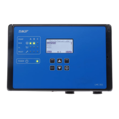
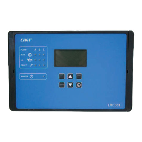
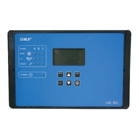
SKF LMC 301 Series User manual

951-150-029-EN
This description is intended as an overview of installation for the LMC 301 Lubrication
Monitor Controller. It does not replace the assembly instructions for the LMC 301 controller.
These are contained on the enclosed USB stick. The assembly instructions can be ordered in
paper format from SKF Lubrication Systems Germany GmbH or Lincoln Industrial, One
Lincoln Way, St. Louis, MO 63120-1578 USA.
In case of discrepancies between the assembly instructions and the Quick Guide, the information
in the assembly instructions takes precedence.
for control of up to three pumps, each with an SKF Single Line / Progressive
and Dual Line centralized lubrication system containing one to three main lines.
Lubrication Monitor Controller
of series LMC 301
Quick Setup/Installation Guide
Version 03
ATTENTION!
The comprehensive assembly instructions (see page 2) are included on the enclosed USB stick
and can be downloaded from our homepage http://www.skf.com/LMC301/.

Quick Setup/Installation Guide for Lubrication Monitor Controller LMC 301
951-150-029-EN
2
Contents
Quick Setup/Installation Guide 1
1. Safety instructions 3
1.1 General safety instructions 3
1.2 General behavior when handling
the product 3
1.3 Qualified technical personnel 3
1.4 Electric shock hazard 3
1.5 Operation 3
1.6 Assembly/maintenance/malfunction/
decommissioning/disposal 4
1.7 Intended use 4
1.8 Foreseeable misuse 4
1.9 Disclaimer of liability 4
1.10 Referenced documents 4
2. Overview 5
3. Technical data 7
3.1 General technical data 7
4. Assembly 8
4.1 Port dimensions, assembly holes,
and minimum mounting dimensions 8
4.2 Open the control unit 8
4.3 Assembly of the control unit 8
4.4 Electrical connection
4.4.1 General 9
4.5 Line routing 9
4.6 Connecting wires 9
4.7 Terminal board 100 to 240 VAC 10
4.7.1 Terminal board 24 VDC 10
4.7.2 Power supply
100 to 240 VAC and 24 VDC 11
4.7.3 Terminal strip for relay outputs 11
4.7.4 Load switching relay 11
4.7.5 Terminal strip for digital inputs 12
4.7.6 Terminal strip for analog capable inputs 12
4.8 Adding an additional IO connection
to RS485 interface 12
5. Configuration by operator/local admin 13
5.1 Configuration of the controller unit
with PC software 13
5.2 Configuration of the controller unit
via the display on the controller unit 13
5.2.1 Status/overview 13
5.2.2 Main menu 13
5.2.3 General setting options 14
5.2.4 Menu structure for system
configuration 15
5.3 Configuration of several IO boards
to master slaves 16
5.3 Menu navigation for operators
without password access 17
5.4 Menu navigation for local admins
with password access 18
6. System configuration 19
Single Line
Menu navigation for system configuration:
6.1 Single Line pump settings with
Supervisor password 19
6.2 Single Line zone settings 20
Progressive
Menu navigation for system configuration:
6.3 Progressive pump settings with
Supervisor password 21
6.4 Progressive zone settings 22
Dual Line
Menu navigation for system configuration:
6.5 Dual Line settings with Supervisor
password 23
6.6 Dual Line Zone control
6.6.1 with two 3/2 solenoid valves or
with EMU 2 24
6.6.2 with EMU 3 25
6.6.3 with DU1 26
6.6.4 with MA/MP 27
Information symbols within the text
Symbol Meaning
Prompts an action
o Used for itemizing
Refers to other facts, causes,
or consequences
Provides additional informa-
tion within procedures
Abbreviation Designation
DI Digital Input
AI Analog Input
DO Digital Output
AO Analog Output
BA
Operating instructions
LMC 301 for:
Single Line lubrication system
Document No.
951-180-067-EN
Progressive system
Document No.
951-180-068-EN
Dual Line system
Document No.
951-180-069-EN
M
Software manual for
LMC 301 PC Software
Single Line lubrication system
Document No.
404679A
LMC 301 Versions
Master Order Number
24 VDC 086500
100 to 240 VAC 086501
Slave Order Number
24 VDC I/O 086502
100 to 240 VAC I/O 086503

Quick Setup/Installation Guide for Lubrication Monitor Controller LMC 301
951-150-029-EN 3
1. Safety instructions
1.1 General safety instructions
The operator must ensure that the instruc-
tions are read and fully understood by all per-
sons tasked with working on the product or
who supervise or instruct such persons. The
operator must also ensure that the staff fully
understands the content of the instructions.
The instructions must be kept readily avail-
able together with the product.
The manual forms part of the product and
must accompany the product if sold to a new
owner.
The product described here was manufac-
tured according to the state of the art.
Risks may, however, arise from its usage and
may result in personal injury or damage to
material assets.
Any malfunctions affecting safety must be
remedied immediately.
In addition to the assembly instructions/oper-
ating instructions, all statutory regulations
and other regulations for accident prevention
and environmental protection must be
observed.
1.2 General behavior when handling the
product
o
The product may only be used in awareness
of the potential dangers, in proper technical
condition, and according to the information
in this manual.
o Personnel must familiarize themselves with
the functions and operation of the product.
The specified assembly and operating steps
and their sequences must be observed.
o Any unclear points regarding proper condi-
tion or correct assembly/operation must be
clarified.
Operation is prohibited until issues have
been clarified.
o Unauthorized persons must be kept away.
o All safety instructions and in-house in-
structions relevant to the particular activity
must be observed.
o Responsibilities for different activities must
be clearly defined and observed. Uncer-
tainty seriously endangers safety.
o Protective and safety mechanisms cannot
be removed, modified, nor disabled during
operation and must be checked for proper
function and completeness at regular in-
tervals.
If protective and safety mechanisms must
be removed, they must be installed im-
mediately following conclusion of work and
checked for proper function.
o Any malfunctions that occur must be
resolved according to responsibility. The
supervisor must be notified immediately
in case of malfunctions outside one's indi-
vidual scope of responsibility.
o Wear personal protective equipment.
o Observe the relevant safety data sheets
when handling lubricants/equipment.
1.3 Qualified technical personnel
Only qualified technical personnel may install,
operate, maintain, and repair the products
described here.
Such persons are familiar with the relevant
standards, rules, accident prevention regula-
tions, and assembly conditions as a result of
their training, experience, and instruction.
They are qualified to carry out the required
activities and in doing so recognize and avoid
any potential hazards. The definition of quali-
fied personnel and the prohibition against
employing non-qualified personnel are laid
down in DIN VDE 0105 and IEC 364. Relevant
country-specific definitions of qualified tech-
nical personnel apply for countries outside the
scope of DIN VDE 0105 or IEC 364.
The core principles of these country-specific
qualification requirements for technical per-
sonnel cannot be below those of the two stan-
dards mentioned above.
The operator is responsible for assigning
tasks and the area
of responsibility.
The personnel must be trained and instructed
prior to beginning work if they do not possess
the requisite knowledge.
Product training can also be performed by
SKF in exchange for costs incurred.
1.4 Electric shock hazard
WARNING
Electric shock
Work on the Lubrication Monitor
Controller may be performed only
by qualified and trained personnel
authorized to do so by the operator.
De-energize the product prior to
beginning work.
Local conditions for connections and
local regulations (e.g., DIN, VDE)
must be observed.
Serious injury or death and property
damage may result from improperly
connected products.
1.5 Operation
The following must be observed while work-
ing on the product.
o All information within this manual and
the information within the referenced
documents.
o All laws and regulations that the operator
must observe.
Quick Setup/Installation Guide for Lubrication Monitor Controller LMC 301
951-150-029-EN
4
All relevant persons (operating personnel,
supervisors) must be informed of the activity
prior to beginning work.
Precautionary operational measures / work
instructions must be observed.
o Take appropriate measures to ensure that
moving/detached parts are immobilized
during the work and that no body parts can
be pinched by unintended movements.
o Assemble the product only outside the
operating range of moving parts, at an ade-
quate distance from sources of heat or cold.
o Prior to performing work, the product and
the machine/system in which the product
will be integrated must be depressur-
ized and secured against unauthorized
activation.
o All work on electrical components may be
performed only with voltage-insulated
tools.
o Fuses must not be bridged. Always replace
fuses with fuses of the same type.
o Ensure proper grounding of the product.
o Drill holes required for assembly only on
non-critical, non-load-bearing parts.
o Other units of the machine/the vehicle must
not be damaged or impaired in their func-
tion by the installation.
o No parts of the centralized lubrication sys-
tem may be subjected to torsion, shear, or
bending.
o Use suitable lifting gear when working with
heavy parts.
o Avoid mixing up/incorrectly assembling dis-
assembled parts. Label parts.
o The installation of the cable glands and the
customer provided cord sets to be done by
the customer. The customer is responsible
for proper installation.
o Cable glands and conduits -see Operating
instruction, chapter 10-Accessories.
o When mounting the customer connecting
cable no rigid connection pipe must be used
- see page 8, Fig. 1, sign (1) on the
controller ground
1.6 Assembly/maintenance/malfunction/
decommissioning/disposal
1.7 Intended use
The Lubrication Monitor Controller is used to
control up to three pumps, each with a one-
to-three-zone (one to three main lines)
SKF Centralized lubrication system.
LMC 301 designs 86501 and 86503 (IO
module) are powered via 100 to 240 VAC
mains provided by the customer. They must
be connected in accordance with DIN, VDE
regulations.
LMC 301 designs 86500 and 86502 (IO
module) are powered via 24 V DC.
The technical information contained in these
instructions must be followed.
Any other usage is deemed non-compliant
with the intended use.
1.8 Foreseeable misuse
Any usage of the product differing from the
aforementioned
conditions and stated purpose is strictly
prohibited.
Particularly prohibited are:
Use for other control tasks
o Use in an explosion protection zone
o Use to feed, forward, or store hazardous
substances and mixtures as defined in An-
nex I Part 2-5 of the CLP Regulation
(EC 1272/2008)
o Use to feed / forward / store gases, lique-
fied gases, dissolved gases, vapors, or fluids
whose vapor pressure exceeds normal at-
mospheric pressure (1013 mbar) by more
than 0.5 bar at their maximum permissible
operating temperature
The manufacturer shall not be held liable for
damage resulting from:
o Failure to comply with these instructions
o The use of lubricants/media not approved
for the unit type
o Contaminated or unsuitable lubricants
o Installation of non-original SKF
components
o Non-compliant usage
o Improper assembly, configuration or filling
o Improper reaction to malfunctions
o Non-observance of maintenance intervals
o Independent modification of system
components
1.9 Disclaimer of liability
1.10 Referenced documents
In addition to this manual, the following docu-
ments must be observed by the respective
target group:
o Operational instructions / approval rules
o Instructions from suppliers of purchased
parts
o Manual for the insulation resistance tester
o Project planning documents and other rel-
evant documents
The operator must supplement these docu-
ments with applicable regulations for the
country of use.
The documentation must be included if the
product is transferred to a new operator.

Quick Setup/Installation Guide for Lubrication Monitor Controller LMC 301
951-150-029-EN 5
Display and control elements of control screen
Symbol Designation Function
Display o Menu display / Display of values and parameters / Fault notification
o The right bar ( ) indicates that the menu extends beyond the current display
PUMP PUMP
Pumps A B C
Pump / Main line A / B / C per pump
max. 3 main lines supported
RUN RUNning
Active control
LED lights up =
Indication of currently active pump/control line (A/B/C)
LL Low Level
minimum fill level reached
LED lights up =
minimum fill level (pump A / B / C) reached
FA U LT FA U LT
Error notification
o LED flashes = error detected
o LED lights up = fault
POWER POWER Control unit on/off LED lights up = Control unit on
Function keys Control key in combination with the display above the key
"Up" arrow key menu control <Back menu level> / increase input value
"Down" arrow key menu control <Forward menu level> / reduce input value
Pressing triggers an interim lubrication.
By briefly pressing follows the choice of an additional lubrication.
Actuations while in configuration mode are ignored.
RESET Long pressing (> 3 seconds) stops all systems or resets an error message.
Long pressing acknowledges and clears error messages.
RESET
P U M P A B C
RUN
LL
FA U LT
POWER
RESET
LMC 301
Display elements of control screen
Symbol Status Function
Stopped/OFF o The system was stopped by pressing the Reset key and can be restarted by briefly pressing the Running key.
Pause o The respective lubrication area is currently in the interval time.
Wait Temperature o Temperature waiting time
Wait o Lubrication zone waiting because another zone currently being lubricated
Lubricate o The system lubricates
Hold o Holding time
Pressure relief o System relieved
Runtime o Pump runs
Secured/
Access denied o No access as local admin or supervisor
Access o Access as local admin or supervisor
Fault o There is a fault.
Digital inputs/out-
puts on o Digital output switched on
Digital inputs/out-
puts off o Digital output switched off
T
!
2. Overview

Quick Setup/Installation Guide for Lubrication Monitor Controller LMC 301
951-150-029-EN
6
Status Overview and triggering an additional lubrication
Symbol Status Function
Press the arrow key to receive a status overview of the pumps resp. zones
(P1Z1 = Pump 1/Zone1 to max. P3Z3 Pump 3/Zone 3).
Press the arrow key again to display the residual pause time resp. residual runtime of the currently
selected pump/zone (e. g. P1Z1).
Press the arrow key again to display the activated inlets of the currently selected pump/zone.
Press the arrow key again to display the activated outlets of the currently selected pump/zone.
Press the "additional lubrication" key shortly to carry out an additional lubrication of the entire system
respectively of the activated zones (P1Z1 = pump 1/zone1 to max. max. P3Z3 pump 3/zone 3).
Overview States
P1Z1
P1Z2
P1Z3
States/Timer P1Z1
P1Z1
State: Hold (Pause/Lube)
Cycle Time:
Inputs (1) P1Z1
State: Lube
Outputs (1) P1Z1
State: Lube
Pump: O
Valve A/B: O
Additional lubrication
komplett
P1Z1
P1Z2
P1Z3

Quick Setup/Installation Guide for Lubrication Monitor Controller LMC 301
951-150-029-EN 7
3. Technical data
3.1 General technical data
Characteristics, design
General
Mounting position Vertical, refer to graphic, see page 14
Dimensions (L x W x H) 10.6299 x 6.6929 x 3.5433 in
Display 2.3622x1.1811 in 128x64 pixels
Environmental conditions
Altitude, up to AC 2000m / DC 5000m
Ambient/Operating temperature AC 14 to + 122 °F
Ambient/Operating temperature DC- - 40 to + 158 °F
Maximum relative humidity 80 % for temperatures up to
31 °C decreasing linearly to
50 % relative humidity at 40 °C
The LCD display only operates
down to -4°F
Storage temperature - 40 to + 158 °F
Application
≤ 150 VAC, indoor/outddor applications 3),
UL overvoltage category III, pollution degree 2
> 150 ≤ 240 VAC only for indoor applications,
UL overvoltage category II, pollution degree 2
Connectivity via terminal block
Inputs: 10 count, short-circuit-proof, 2 are analog capable
Outputs: 8 count, relay outputs NO-contact 8A
of 2 to max. 15A
Residual ripple relative
operating voltage ±5% acc. to DIN 417 55
Protection and monitoring
Current limit Sustained short-circuit-proof
Overload-proof/ Open-circuit-proof Yes
Protection class 1) 4)
IP 65, protection class only with appropiate
cable glands PG-M20, without UL certification
Characteristics, design
Electronic consuming
Iternal fuse (LMC-Controller) 3 A
Input AC
Input voltage 100-240 VAC (50/60Hz)
customer Fusing (slow). 4 A (100-240 VAC)
Input DC 2) 3)
Input voltage 24 V DC ±10%
custermer Fusing (slow) 10 A
Output rating relays
Connection directly to the relay 01/02 100-240 VAC/ max. 15A
Connection directly to the relay 01/02 24 VDC/ max. 15A
Output terminal block 01 bis 08 24 VDC; 100-240 VAC/max. 8A
Note:
Do not mix 2 different voltages together (AC and DC) on
one terminal block!
Safety per DIN EN 60204-1
Safety class Class I
Customer connection cables
Temperature resistance of >158 °F
EMC
Interference suppression VDE 0875 T 11, EN 55011 Class A
Emitted interference acc. to EN 61000-6-3
Immunity acc. to EN 61000-6-2
Note
The emitted interference meets the requirements for industrial
use; use in a residential area may cause interference under some
circumstances.
LMC 301 Version Order No.
24 VDC 086500
100 to 240 VAC 086501
24 VDC I/O 086502
100 to 240 VAC I/O 086503
1) strain relief kid/cable glands -see Operating instructions.
2) Applicable precautions for proper operation: “ Protective Extra Low
Voltage“ (PELV) and “Safe Extra Low Voltage“ (SELV).
3) The application as Outdoor (outdoor installation) has not been tested
in connection / certification with the UL standard
4) The degree of protection class for the controller LMC301 has not
been tested in connection with the UL certification

Quick Setup/Installation Guide for Lubrication Monitor Controller LMC 301
951-150-029-EN
8
4. Assembly
Fig. 1
4.1 Port dimensions, assembly holes, and minimum mounting dimensions
Minimum mounting dimensions
A = width: 12.99 in
B = height 17.72 in
C = depth 13.78 in
4.2 Open the control unit
Opening the controller unit, Fig. 2
• Insert a flat tip screwdriver (1) with a maxi-
mum blade width of 5.5 mm into the open-
ing slot (2).
• Tilt the screwdriver (1) slightly to the right
to open the cover (3).
)Open the cover by briefly clicking and then
opening the cover by hand.
) see Figures 1 and 2
1
2
3
∅
C
B
A
6.02
10.31
9.72
10.67
6.6899
2.76
3.54
105 °
0.17
0.04
PUMP A B C
RUN
LL
FA U LT
POWER
RESET
LMC 301
4.3 Assembly of the control unit
) See Figure 1
The controller unit is installed using 4
cheese-head screws of thread size M4.
If M4 tapped bores are used to fasten the
unit, the screws must have a minimum length
of 15 mm.
Fastening material to be provided by the
customer:
o Cheese-head screws with hexagon socket
4x acc. to DIN6912-M4x. -8.8
o Washers (4x) acc to.
DIN EN ISO 7090-4-200HV
o Self-locking nuts M4 (4x) acc. to
DIN EN ISO 10511; drill assembly holes
(Ø 4.3 mm) acc. to assembly drawing
(Fig. 4) and the conditions on the surface.
• Clean surface to remove drilling chips.
• Open the control unit, place it on the sur-
face and roughly align it.
• Pass cheese-head screws (4x) through
the fixing holes on the controller unit and
mounting surface.
• Apply washers to cheese-head screws,
gently tighten cheese-head screws.
• Align the controller unit, tighten cheese-
head screws.
Torque 4 Nm

Quick Setup/Installation Guide for Lubrication Monitor Controller LMC 301
951-150-029-EN 9
ATTENTION!
The mains voltage (supply voltage) must
match the specifications on the rating
plate of the Lubrication Monitor Controller.
Check the fuse protection of the electrical
circuit. Use only fuses with the prescribed
amperage,
4.4 Electrical connection
4.4.1 General
The controller unit is supplied with
110 to 240 V AC voltage or optionally with
24 V DC voltage.
In both designs, the cables are introduced
through a cable fitting with a clamping range
of Ø 4.5 mm to Ø 10 mm and terminal blocks
with tension springs (maximum conductor
cross-section 2.5 mm, conductor stripping
length 15 mm).
Consult Chapter 3, Technical Data, for the
electrical characteristics of the controller unit.
The connections on the controller
unit are established according to the custom-
er-specific design of the lubrication system/
main lines. The system manufacturer is thus
responsible for correct connection to the con-
troller unit.
WARNING
Electric shock
De-energize the control unit prior to
beginning work.
Only qualified personnel authorized
by the operator may perform work
on controller unit.
The electrical operating conditions
and local regulations (e.g., DIN, VDE)
must be observed.
ATTENTION!
The Lubrication Monitor Controller
contains electronic components that
can be destroyed by accidental elec-
trostatic charge or discharge (ESD).
To prevent possible damage due to
ESD, hands and any tools must be
discharged on a bare grounded posi-
tion on the installation site prior to
performing any work on the opened
control unit. Conductors or compo-
nents within the device must not be
touched under any circumstances.
) See Figures 4 and 5
4.5 Line routing
The lines are laid through cable glands at-
tached on both sides and on the bottom.
The attached cable glands are provided for the
following lines:
optional Left-side cable glands:
Power supply
Master/Slave connection
optional Right-side cable glands
Relay outputs (load-dependent)
Pump motor
Cable glands on bottom:
Inputs and outputs of monitoring units
(sensors)
• Loosen the cable fitting.
• Draw the connection cable provided by cus-
tomer into the cable fitting.
• Connect the connection cable (provided by
customer) according to the wiring diagram
(see Figs. 6 to 12).
• Tighten the cable fitting.
) see Figures 4 and 5, item 1, and Figure 3
The wires on the terminal strips for:
o power connection (item 1)
o digital outputs (item 2)
o analog outputs (item 3)
o relay (item 4)
are connected via a tension spring mecha-
nism. The following procedure should be used
for this
• Press the tension spring back using the flat
tip screwdriver.
• Insert flexible cable leads into the terminals.
• Release pressure on the tension spring.
• Check the wiring for tight fit.
4.6 Connecting wires
Fig. 3
Wires, stripped
Length 15 mm
Terminal strip Tension spring
Flat tip screwdriver
maximum cable insulation section
to customer-sided of cable 2.5 mm2.
ATTENTION!
You can run each terminal block (4.1 or 4.2) only
with one operating voltage (24VDC or
100 to 240 VAC). Do not mix 2 different voltages
together on 1 terminal block.
ATTENTION!
An appropriate switch or circuit-breaker
(min. 10A) who protect all pole must be
included in the building installation and shall
be in close proximity to the equipment within
easy reach of the OPERATOR.
The disconnecting device shall be marked as
the device for the equipment.

Quick Setup/Installation Guide for Lubrication Monitor Controller LMC 301
951-150-029-EN
10
4.7 Terminal board 100 to 240 VAC
4.7.1 Terminal board 24 VDC
Connections on mainboard, 100 to 240 VAC design, Fig. 4
Cable glands for
sensors
Cable glands for power supply/interface Cable glands for valves/motor
Legend to Figure 4
Item Description BA-Chapter
1Power supply X1 4.7.2
1a
Internal 100 to 240 VAC con-
nection for the AC/DC power
supply unit
1b
Internal 24 VDC connection
from AC/DC power supply unit
to the board
2Digital inputs X2 4.7.6
3Digital/Analog inputs X3 4.7.7
44.1 Relay outputs X4 4.7.3
4.2 Relay outputs X4
5RS485-Interface
624 VDC output for mainboard
7USB port (external)
Not for User
8DIP switch addresses 4.8
9RESET switch Hardware Reset
10 Fuse (FK1) 3A
11 Load switching relay (2x) X5 4.7.5
12 PE/Ground terminals for relay
outputs X6
4.7.4
Connections on mainboard, 24 VDC design, Fig. 5
Cable glands for power supply/interface Cable glands
for valves/motor
Legend to Figure 5
Item Description BA-Chapter
1Power supply X1 4.7.2
2Digital inputs X2 4.7.6
3Digital/Analog inputs X3 4.7.7
44.1 Relay outputs X4 4.7.4
4.2 Relay outputs X4
5RS485 Interface
624 VDC output for main board
7USB port (external)
Not for User
8DIP switch addresses 4.8
9RESET switch
Hardware Reset
10 Fuse (FK1) 3A
11 Load switching relay (2x) X5 4.7.5
12 PE Ground terminals for relay
outputs X6
4.7.4
1a 1 10 1b 2 11 4.2
6 5 8 7 9 3 12 4.1
1 10 2 11 4.2
6 5 8 7 9 3 12 4.1
Cable glands
for sensors

Quick Setup/Installation Guide for Lubrication Monitor Controller LMC 301
951-150-029-EN 11
X1
X1
4.7.2 Power supply
100 to 240 VAC and 24 VDC
Terminal diagram 100 to 240 V AC, Fig. 6
) see Figure 4, item 1, and Fig. 6
Terminal diagram 24 VDC, Fig. 7
• Connect customer-provided cable for
power supply acc. to terminal diagram
24 VDC, Fig. 7.
• Connect customer-provided cable for power
supply acc. to terminal diagram
100 to 240 VAC, Fig. 6.
)The 24 VDC is generated internally. Do not
connect externally generated 24 VDC to ter-
minal + or terminal -.
) see Figure 5, item 1, and Fig. 7
4.7.3 Terminal strip for relay outputs
)see Figures 4/5, item 4, and Figures 9 to 10
Connections in conjunction
with load switching relay
max. 8 A
Terminal diagram for relay outputs, Fig. 9
O 4
O 4
O 3
O 3
O 2
O 2
O 1
O 1
O 8
O 8
O 7
O 7
O 6
O 6
O 5
O 5
O = O u t p u t
Terminals
O3 to O8
max. 8 A
Connections in conjunction
with load switching relay
max. 8 A
X4
ATTENTION!
You can run each terminal block (4.1 or 4.2)
only with one operating voltage (24VDC or
100 to 240 VAC). Do not mix 2 different
voltages together on 1 terminal block.
4.7.4 Load switching relay
) see Figures 4/5, item 11, and Fig. 8
Proposal Load switching relay, Fig. 8
• Connect (loop) customer-provided load
voltage cable to both terminals of the load
relay.
O 3
O 2
O 2
O 1
O 1
Input 230 VAC
max. 15 Ampere
Input 230 VAC
max. 8 Ampere
Input 230 VAC
max. 8 Ampere
Input 230 VAC
max. 15 Ampere
M
Output
max. 8 Ampere
M
Relay 2
Relay 1
Connection up to
max. 8 amperes
Load relay
controlled
directly
X5
Connection example for relay outputs, Fig. 10
O 4
O 4
O 3
O 3
O 2
O 2
O 1
O 1
O 8
O 8
O 7
O 7
O 6
O 6
O 5
O 5
G r ound
Power
Signal
monitoring
Reversing valve
Pump motor
Connection
max.
8 amperes
X6
4.1
4.2
4.1
4.2

Quick Setup/Installation Guide for Lubrication Monitor Controller LMC 301
951-150-029-EN
12
4.7.6 Terminal strip for analog capable inputs
Terminal strip for analog capable inputs,
Fig. 12
+
I 1
I 2
_
I = Input
The analog inputs are provided for:
o Pressure transducer
o Temperature switch
o Switch polled in mA or volt, e.g., 4-20 mA,
1-6 volt, etc.
• Connect power supply for analog switch (+)
to plus terminal (+).
• Connect ground connection for analog
switch (-) to minus terminal (-).
• Connect signal line for analog switch to cor-
responding input terminal (I1 /I2).
)see Figures 4/5, item 3, and Fig. 12
X3
Plus
Minus
The digital inputs are provided for:
o Pressure switch
o Proximity switch
o Flow sensor
o Fill level switch
o Interim lubrication switch
• Connect power supply for digital switch (+)
to plus terminal (+).
• Connect ground connection for digital switch
(-) to minus terminal (-).
• Connect signal line for digital switch to cor-
responding input terminal (I3 to I10).
1) No grounding connection (minus) is supported for
two-wire sensor designs (plus + signal).
4.8 Adding an additional IO connection to
RS485 interface
)see Figures 4/5, item 8
)see Figures 13/14
ATTENTION!
A separate address must be assigned to each
IO board!
To differentiate between multiple IOPCBs in
an RS485 daisy chain, each IOPCB needs its
own address.
This can be set in the binary code using the
DIP switch (address switch).
If all four DIP switches are set to top, the
address is "1". See Figure 13 for further
addresses.
Another IPCB communication connection can
be established using the two RS485 connec-
tors (5).
Up to 7 IOPCBs can be connected to a
mainboard. Each IOPCB must be supplied
separately.
Set IO addresses, Fig. 13
ON
1 2 3 4
ON
1 2 3 4
ON
1 2 3 4
ON
1 2 3 4
ON
1 2 3 4
ON
1 2 3 4
ON
O
ON
1 2 3 4
ON
1 2 3 4
Address 1 Address 2
Address 3 Address 4
Address 5 Address 6
Address 7 Address 8
Adr. 1
Adr. 2
Adr. 8
Daisy chain with external IO boards, Fig. 14
ATTENTION!
Use shielded cables.
Maximum cable length 200 m.
+
)see Figures 4/5, item 2, and Figure 11
4.7.5 Terminal strip for digital inputs
Terminal strip for digital inputs, Fig. 11
+
I 3
I 4
-
+
I 5
I 6
_
+
I 7
I 8
-
+
I 9
I10
_
I = Input
X2
Plus
Minus 1)
1) No grounding connection (minus) is
supported for two-wire sensor designs
(plus + signal).

Quick Setup/Installation Guide for Lubrication Monitor Controller LMC 301
951-150-029-EN 13
5. Configuration by operator/local admin
General
There are two options for configuring the
controller:
o Configuration with PC software and USB
connection -see Chapter 6.1.
o The PC software application is designed for
Windows XP, Windows 7, and Windows 8
operating systems and is included as data
media with the controller. The software can
also be downloaded as freeware from the
SKF website. After installing the program,
data transfer occurs via the USB interface
in the controller.
o SKF recommends this procedure for initial
installations.
o Configuration of the system using the
display attached to the controller and the
menu keys - see Chapter 5.1.
o The complete configuration can be done
via the controller display and the associ-
ated menu keys.
5.1 Configuration of the controller unit
with PC software
)see Figure 15
• From the SKF homepage
http://www.skf.com/LMC301/
• Download software
LMC 301 PC Software
• Close all applications on the laptop.
• Open the file.".
)After you enter the password, the LMC 301
software installs automatically. SKF recom-
mends not starting any other applications
during this period.
ATTENTION!
The USB cable may only be
connected to the USB port installed inside
the controller lid on the LMC 301.
- see Fig. 15.
Connect the USB cable, Fig. 15
2
1
• Install the controller unit (Chapter 4.3).
• Open the controller unit (Chapter 4.2).
• Connect the USB cable (2) from the laptop
on the inside of the controller lid (1) and
turn on the power supply.
• Start the LMC 301 software.
)The description of the PC configuration is
included with the software.
• Configure according to the included de-
scription for configuration on the PC.
5.2 Configuration of the controller unit via
the display on the controller unit
5.2.1 Status/overview
After switching on the supply voltage, the
Overview States menu appears on the
display.
The current parameter settings and values
are displayed. This is done continuously and
automatically.
The parameters and settings can optionally be
accessed using the two arrow keys .
No entries can be made and the symbol
shows a closed lock
.
To change the configuration, select the Menu
menu item using the control key .
This will take you to the Main menu.
Changes can be made within the main menu
only after entering the password. This is done
in the Login settings menu level.
When entering the password, there is a dif-
ferentiation between Local Admin (customer
access) and Supervisor (only service staff, no
customer access).
The open lock icon indicates that the system
has been unlocked.
5.2.2 Main menu
Main menu, Fig. 16
Main menu
Login settings
User settings
Device settings
Pump 1 Timings
Information
Back OK
ATTENTION!
The description of the main menu is based
on settings that the end customer can adjust.
(password level Set PW local admin)

Quick Setup/Installation Guide for Lubrication Monitor Controller LMC 301
951-150-029-EN
14
The main menu shows the following options:
Login settings
The <Login settings> menu is used to manage
access to the menus with a password. The
password can also be changed here.
User settings
(Setting options for operators without pass-
word access)
In this menu, the measurement units (metric
or inch) and the language for the user menu
can be selected.
Device settings
In this menu, the display properties of the
screen, such as backlight and contrast, can be
modified. The date and time are also set here.
Pump 1 Timings
In this menu, the timing of the pump and the
settings for the associated main line are set.
Information
The hardware and firmware versions
are stored in this menu. The hours of con-
troller operation, the error history, and the
serial number of the controller unit can also
be viewed here.
5.2.3 General setting options
User settings
Key Display Description
User settings - Set units and menu language
1
• Press <control key Menu>
)You will be taken to the main menu.
2
• Use <down arrow key> to select the User set-
tings menu item.
• Confirm with <control key OK>.
) You will enter the User settings menu.
3
• Use <down arrow key > to select the menu item
Language [English /Deutsch].
• Press <control key Select>.
• Use <down/up arrow key> to select the lan-
guage [English /Deutsch].
• Press <control key Save>.
4
• Use <up arrow key > to select the Unit Settings
menu item [Imperial/Metric].
• Press <control key Select>.
• Use <down/up arrow key> to select Unit Set-
tings [Imperial/Metric].
• Press <control key Save>.
• Press <control key Back>.
)You will return to the User settings menu.
Login settings- Enter Set PassWord local admin.
• Press <control key OK>.
• Use <down/up arrow key> to select Set Pass-
Word local admin.
• Press <control key OK>.
)You will enter the Enter Password menu. The
password contains four characters that can be
either numerals or letters.
• Use <down/up arrow key> to set the first char-
acter of the password.
• Confirm the entry with <control key OK>.
• Repeat the entry for the following 3 password
characters.
• Press <control key Back>.
)You will return to the Login Settings menu.
Main menu
Login settings
User settings
Device settings
Pump 1 Timings
Information
Overview States
P1Z1:
User settings
Unit Settings
[Metric ]
Language
[Deutsch ]
Back Select
User settings
Unit Settings
[Metric ]
Language
[Deutsch ]
Back Select
Main menu
Login settings
User settings
Device settings
Pump 1 Timings
Information
Enter Password
Please Enter Password
to Continue
0000
Cancel OK
Login settings
Enter Password
Set PW local admin
Set PW Supervisor
Back OK
Password Correct
You are logged in as
Local Admin
Back OK
User type Password
Operator without password access
Local admin 1000
Suppervisor 2020

Quick Setup/Installation Guide for Lubrication Monitor Controller LMC 301
951-150-029-EN 15
System configuration
Key Display Description
System configuration - Amount of pumps, Pump settings, Set Params to Default
- only in Supervisor password level
1
)Requirements: Supervisor password level is
enabled.
• Use <down/up arrow key> to select System
configuration.
• Press <control key OK>.
)You will enter the System configuration menu.
)You will be asked "Lubrication will be
stopped- Continue?"
• Press <control key Yes>.
)You will enter the System configuration menu.
The following settings can be made:
o Amount of pumps
o Setting the pumps
o Set Params to Default
Main menu
Login settings
User settings
Device settings
Pump 1 Timings
System configuration
Information
System configuration
Lubrication will be stopped
Continue?
Yes No
System configuration
Amount of pumps
Setting the pump
Set Params to Default
ATTENTION!
SKF Service menu
This level is password-protected and can-
not be accessed from the operator level or
the Local Admin level. Settings can be made
only in the Supervisor password level.
All essential controller and system settings for
are made in the
System configuration menu level.
These settings can and may only be made
by SKF Service.
5.2.4 Menu structure for system configuration
Select
Back
Back Ok

Quick Setup/Installation Guide for Lubrication Monitor Controller LMC 301
951-150-029-EN
16
5.3 Configuration of several IO boards to master slaves
Chapter 4.8 describes the IOPCB communi-
cation connection between an IO master and
an IO slave.
To connect two boards with each other, the
customer must prepare an adapter cable.
The cable must be shielded.
The plugs required for the adapter cable are
available on the respective board.
In the following please find further notes re-
garding the connection of the adapter cable.
SKF takes a separate voltage supply for each
board as given.
o SKF takes a separate voltage supply for
each board as given.
o The PE connection (ground) must be sepa-
rate for each board. Connection is made on
the respective board, see page 11, Fig. 9.
o The maximum admissible connected load of
each board is 3 A.
o In case of different potential-free outputs
make sure to use an adequate connection
line and a corresponding connection dia-
meter, see chapter 4.7.3.
o For each connection line the customer must
provide a correspondingly designed back-
up fuse.
ON
1 2 3 4
ON
1 2 3 4
ON
1 2 3 4
Connection Adapter Cable
Socket 1 to Socket 1
Socket 2 to Socket 2
Socket 3 to Socket 3
Socket 4 to Socket 4
LMC 301
Master
LMC 301
Slave 1
LMC 301
Slave 2
Wiring and Setting Master/Slave, Fig. 17
Caution!
When preparing the adapter cable use a shielded cable.
Adapterkabel
Master Board
Slave Board
Slave Board
LMC 301 Versions
Master Order No.
24 VDC 086500
100 to 240 VAC 086501
Slave Order Number
24 VDC I/O 086502
100 to 240 VAC I/O 086503

Quick Setup/Installation Guide for Lubrication Monitor Controller LMC 301
951-150-029-EN 17
5.3 Menu navigation for operators without password access
Fig. 18
Login settings
User settings
Device settings
Pump 1 Timings
Pump 2 Timings
Pump 3 Timings
Information
Main menu
Pump 1 Timings
Zone 1 Settings
Zone 2 Settings
Device settings
Backlight
Contrast
[ 60% ]
Date
[ 00/00/00 ]
System Clock
[ 00:00:00 ]
User settings
Unit Settings.
[imperal]
<< >>
[metric]
Language
[German]
<< >>
[English]
Information
HW/FW Version
Hours of Operating
Error history
Serial Number
HW/FW Version
Hardware version
[.....]
Firmware version
[.....]
Hours of operation
Cumulated
operating Time
.................................
Error history
No . 1 .........
!
Serial Number
Serial Number
[00000000]
Zone 1 Settings
Lube load
[Normal Cycle Set] << >> [Heavy Cycle Set]
Zone 2 Settings
Lube load
[Normal Cycle Set] << >> [Heavy Cycle Set]
Login settings
Enter Password
Set PW local admin
Set PW Supervisor
Enter Password
Please enter Password
to Continue
0000
Password correct
You are are logged in as
Local Operator
[enabled
<< >>
disabled]
Login settings
User settings
Device settings
Pump 1 Timings
Information
Lube Event Counter
P1Z1
[ 0]
P1Z2
[ 0]
P1Z3
[ 0]
Lube Event Counter

Quick Setup/Installation Guide for Lubrication Monitor Controller LMC 301
951-150-029-EN
18
5.4 Menu navigation for local admins with password access
Fig. 19
Login settings
User settings
Device settings
Pump 1 Timings
Pump 2 Timings
Pump 3 Timings
Informationen
Main Menu
Device settings
Backlight
Contrast
[ 60% ]
Date
[ 00/00/00 ]
System Clock
[ 00:00:00 ]
User settings
Unit Settings
[imperial]
<< >>
[metric]
Language
[German]
<< >>
[English]
Login settings
Enter Password
Set PW local admin
Set PW Supervisor
Enter Password
Please enter Password
to Continue
0000
Passwort correct
You are logged in as
Local Operator
Login settings
Enter Password
Set PW local admin
Set PW Supervisor
Login settings
[enabled
<< >>
disabled]
Local User
Old Password
0000
New Passwort
0000
Pump 1 Timings
Zone 1 Settings
Zone 2 Settings
Zone 1 Settings
Lube Load
[normal Cycle Set] << >> [Heavy Cycle Set]
Normal Cycle Time
[ 0000: 00:00 ]
Heavy Cycle Time
[ 0000: 00:00 ]
Lube Time
[ 00: 00:00 ]
Holding Time
[ 00:00 ] s
Zone 2 Settings
Lube Load
[Normal Cycle Set] << >> [Heavy Cycle Set]]
Normal Cycle Time
[ 0000: 00:00 ]
Heavy Cycle Time
[ 0000: 00:00 ]
Lube Time
[ 00: 00:00 ]
Holding Time
[ 00:00 ] s
Login settings
Device settings
Pump 1 Timings
User settings
Information
HW/FW Version
Hours of Operating
Error history
Serial Number
HW/FW Version
Hardware version
[.....]
Firmware version
[.....]
Hours of operation
Cumulated
operating Time
.................................
Error history
No . 1 .........
!
Serial Number
Serial Number
[00000000]
Information
Lube Event Counter
P1Z1
[ 0]
P1Z2
[ 0]
P1Z3
[ 0]
Lube Event Counter
Local Admin password
factory setting: 1000
Main line settings (zone)

Quick Setup/Installation Guide for Lubrication Monitor Controller LMC 301
951-150-029-EN 19
6. System configuration
Fig. 20
6.1 Menu navigation for system configuration - Single Line pump settings with Supervisor password
Login settings
User settings
Device settings
Pump 1 Timings
System configuration
Information
Main Menu
Login settings
Enter Password
Set PW local admin
Set PW Supervisor
Enter Password
Please enter Password
to continue
0000
Password correct
You are logged in
as Supervisor
Login settings
System configuration
Amount of pumps
Pump 1 settings
Set Params to Default
Restore Fact.Set
Amount of pumps
Pump 1 settings
Pump settings
Zone 1 Settings
Zone 2 Settings
Pump Settings
System Type
Lube control
Relief Settings
Filling/Low Level
Motor Protection
Temperature Control
System Type
System Type
[ << Single Line >> << Progressive >> << Dual Line >> ]
Zone
[ 2 Zone ]
TZone vent valve type
[ <<2/2 Way Valve NO >> << 2/2 Way Valve NC >> << 3/2 Way Valve>> ]
Lube Control
Pump Output
Output Type
[ <<normally closed>> <<normally open>>
<< disabled>>
Output No.
[ 1,01 ] O
Remote Manual Lube
Input Type
[ <<disabled >> << normally open>>
<< normally closed >>]
Input No.
[1,05] DI
Filling/Low Level
Monitoring
Alarm
Inputs
Timings
Monitoring
Filling Monitoring type
[ << Low Level Detection>> << Auto Filling>> <<disabled>>
Lube Limited By
[ << Lube Cycles>> << Pump time>> << disabled >>
Alarm
Output Type
[ << normally closed>>
<< normally open>> << disabled>>
Output No
[ 1,02 ] O
Inputs
Input LL Type
<< disabled>> << transducer 1-6V >> << transducer4-20 mA >> transducer 0-20mA >>
<<transducer 2-10V >> <<transducer 0-10V>> << normally open>> << normally closed>> ]
Eingang Nr. Leer Nr.
[ 1,03 ] DI
Timings
Filling Timeout
[ 00: 00: 00 ]
Detection LL Time [ 10]
Motor Protection
Motor Protection Type
[ << normally open>> << normally closed>>
<<disabled>>
Input No.
[ 1, 04 ] AI
Relief Settings
Lube Control Mode
Lube Control Mode
[ <<pressure controlled >> <<time controlled >> ]
Sensor at Pump Set.
Sensor Type
[ << disabled>> << transducer 1-6V >>
<< transducer 4-20 mA >> transducer 0-20mA >>
<<transducer 2-10V >> <<transducer 0-10V>>
<< Öffner >> << Schließer >> ]
Input No.
[1,04] DI
Amount of pumps
[<< 1 pump >> << 2 pump>> << 3 pump >>]
Login settings
Relief Settings
Filling/Low Level
Relief Type
[ << enabled>> << disabled>>
Zone Relief Time
[ 0] s
Motor Protection/
Temperature Control
Pump Output
Lube Control Mode
Sensor at Pump Set.
Remote Manual Lube
Additional monitoring
Temperature Control
Internal Sensor
Externalr Sensor
Temperature Limits
Internal Sensor
InternalSensor
[ << disabledt>><< enabled>>]
IO Board
[ 1 ]
External Sensor
Sensortyp
[<< disabled>> << transducer 1-6V >> << transducer 4-20 mA >>
<<transducer 0-20mA >><<transducer 2-10V >> <<transducer 0-10V>>
<<normally closed>> <<normally open>>]
Input
[ 1,02 ] AI
Minimal Valve
[ 0000 ] PSI
Maximal Valve
[ 0000 ] PSI
Note!
Additional buttons for transducer setting
Temperature Limits
Over temperature
[ 180,0 ] F
Under temperature
[ 14,0 ] F
Set Params to Default
Set Params to Default?
Continue?
Restore Fact. Set.
Restore Fact. Set?
Continue?
Supervisor password
factory setting: 2020

Quick Setup/Installation Guide for Lubrication Monitor Controller LMC 301
951-150-029-EN
20
Fig. 21
6.2 Menu navigation for system configuration - Single Line zone settings
Login settings
Cycle Control
Timings
Release/Counter
Lube Load
Timings
Control Mode
[ << time controlled >> << Counder ctrld >> ]
Normal Cycle Time
[0000: 00: 00]
Heavy Cycle Time
[0000: 00: 00]
Release/Counter
Input Type
[ << normally closed >> << normally open >> << disabled >> ]
Input No.
[ 1,06 ] DI
Lube Loade
Input Type
[ << normally open >> << normally closed >> << disabled >> ]
Input No.
[ 1,07 ] DI
Lube Control
Vent Valve
Press. Sensor at EOL
Flow Sensor
Lube Control Time
Vent Valve
Output Type
[ << normally open> <<normally closed >> << disabled>> ]
Output No.
[ 1,03 ] 0
Holding time
[ 00: 00 ] s
Press. Sensor at EOL
Sensor Type
[ << disabled >> << transducer 1-6V >>
<< transducer 4-20 mA >> << transducer 0-20mA >>
<< transducer 2-10V >> << transducer 0-10V >>
<< normally open >> << normally closed >> ]
Input No.
[ 1,01 ] AI
Minimal Valve
[ 0000 ] PSI
Maximal Valve
[ 0000 ] PSI
Deploy Valve
[ 0000 ] PSI
Vent Valve
[ 0000 ] PSI
Lube Control Time
Monitoring Time
[00: 00: 00]
Set Params to Default
Set Params to Default?
Continue?
Flow Sensor
Amnt of Flow Sensor
[ 1]
Input No.1 Typ
[ << normally open>> << normally closed>>
<< disabled>> ]
Eingang Nr. 1
[ 1,08 ] DI
Amount of pumps
Amount of pumps
[<< 1 pump >> << 2 pumps>> << 3 pmps >>]
Login settings
User settings
Device settings
Pump 1 Timings
System configuration
Informationen
Main Menu
System configuration
Amount of pumps
Pump 1settings
Set Params to Default
Pump 1 settings
Pump settings
Zone 1 Settings
Zone 2 Settings
Zone 3 Settings
Zone 1 Settings
Cycle Control
Lube Control
Post Sprayer
Alarm
Login settings
Enter Password
Set PW local admin
Set PW Supervisor
Enter Password
Please Enter Password
to Continue
0000
Password correct
Your locked an as
Subvisor
Login settings
Cycle settings Lubrication intervals
Lubrication timings
Kind of the control
Lubrication time interval
Functionality of her release/-
counter
Functionality of her zone
control and allocation
Zone cycle settings
Control and allocation of the
vent valve
Functionality and allocation of
the pressure sensors
(End of line)
Post Sprayer
Output Type
[ << nomally open >> << normally closed >> << dsabled>> ]
Output No.
[ 1,04 ] 0
Post Spray Time
[ 00: 00 ] s
Alarm
Output Type
[ << nomally open >> << normally closed >> << dsabled>> ]
Output No.
[ 1,06 ] 0
Monitoring and allocation of
the lubrication distributor
Monitoring and allocation of
the lubrication distributor
Note!
Additional buttons for transducer setting
Other manuals for LMC 301 Series
1
Table of contents
Other SKF Controllers manuals

SKF
SKF 086501 User manual

SKF
SKF ST-102P Series User manual

SKF
SKF Magforce DSP Series User manual

SKF
SKF LMC 301 Series User manual

SKF
SKF Ecomag Installation and operating instructions

SKF
SKF CAHB-21 1 Series User manual

SKF
SKF 086500 User manual

SKF
SKF IMx-M User manual

SKF
SKF Magforce STD 10007 series User manual

SKF
SKF 86535 User manual
Popular Controllers manuals by other brands

Johnson Controls
Johnson Controls M9206-DN Series installation instructions

Giacomini
Giacomini K270Y101 quick start guide

Duetech Beres
Duetech Beres STP Lite user manual

Mitsubishi Electric
Mitsubishi Electric MELSEC iQ-F FX5 installation manual

Indigo
Indigo CD13505 instructions

IBM
IBM Netfinity ServeRAID-4L Ultra160 User reference