Contents
Explanation of signal words for safety 2
Safety ......................... 2
Owner/operator responsibility ...... 3
Intended use .................... 3
System overview ................ 3
Description ..................... 3
Specifications ................... 3
Installation ..................... 4
Operation ...................... 6
First use setup ................. 6
Setting cycles per minute ........ 6
Run mode .................... 6
Overrun mode ................. 7
Sleep mode ................... 7
Error codes ................... 7
Replace 9 V battery ............. 8
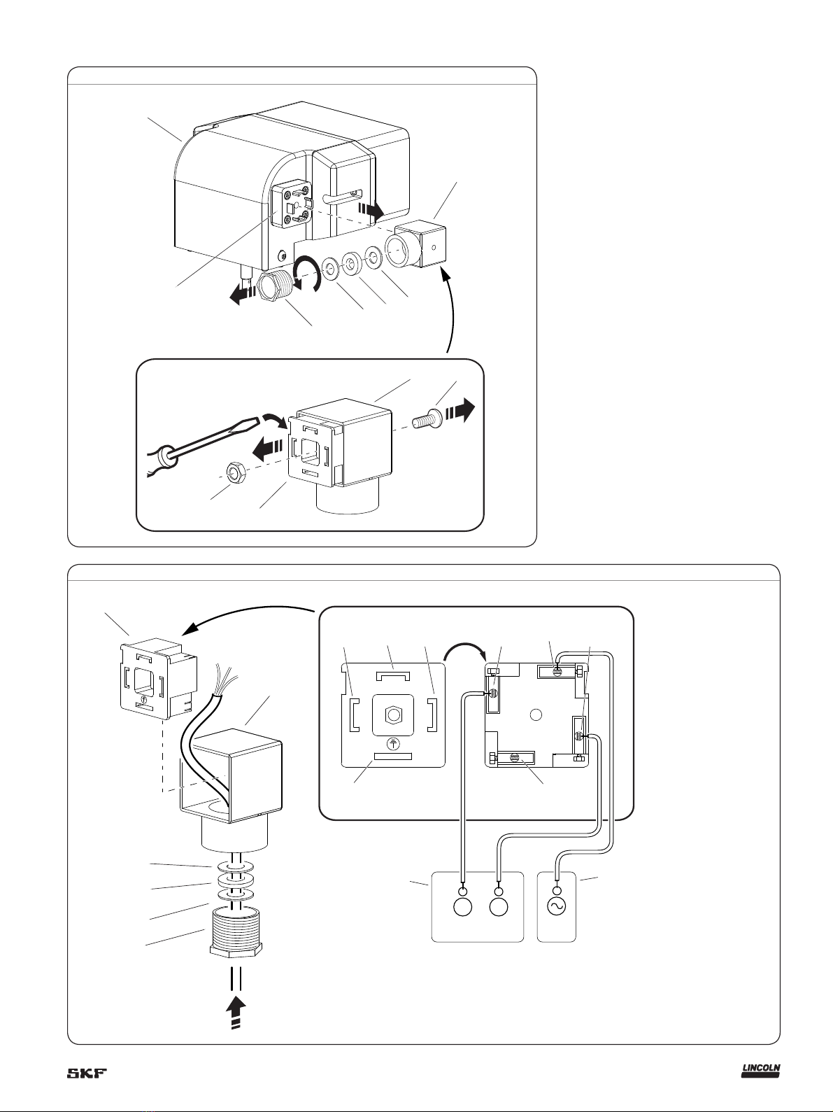
Solenoid replacement
(error code OC) ................ 8
Electronic overrun controller
operation summary .............. 9
Test controller function ........... 9
Lincoln industrial standard warranty 12
Explanation of signal
words for safety
• Do not install or operate controller until
all instructions within this guide are
completely understood.
• Equipment must only be installed,
maintained, and repaired by persons
familiar with these instructions.
• Do not misuse, over-pressurize, modify
parts, use incompatible chemicals or
fluids, or operate with worn and/or
damaged parts.
• Do not exceed the stated maximum
working pressure of the pump or of the
lowest rated component in your system.
• Always read and follow the fluid
manufacturer’s recommendations
regarding fluid compatibility, and the use
of protective clothing and equipment.
• Failure to comply may result in personal
injury and/or damage to equipment. Wear
adequate personal protection each time
the assembly is used or repaired.
• Do not allow oil to contact skin or eyes.
Safety
Read and carefully observe these
instructions before installing, operating or
troubleshooting this equipment.
Indicates a hazardous situation which,
if not avoided, could result in minor or
moderate injury.
CAUTION
Indicates a hazardous situation which,
if not avoided will result in death or
serious injury.
WARNING
Indicates a hazardous situation which,
if not avoided, will result in death or
serious injury.
DANGER
Indicates a hazardous situation which,
if not avoided, will result in death or
serious injury.
SAFETY INSTRUCTIONS
This is the safety alert symbol. It is used
to alert you to potential physical injury
hazards. Obey all safety messages that
follow this symbol to avoid possible
injury or death.
!Notice
Failure to comply with any danger,
warning, caution, or notice, as well as
any unintended or misuse, will result in
loss of claim for warranty or liability for
this equipment.
2