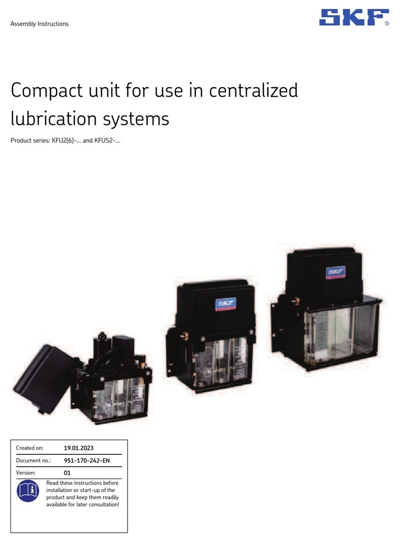
SKF LAGD 400 User manual

Instructions for use
Mode d’emploi
Bedienungsanleitung
Instrucciones de uso
Manuale d’istruzioni
Bruksanvisning
Gebruiksaanwijzing
Instruções de uso
使用说明书
Инструкция по эксплуатации
SKF LAGD 400


Русский
Русский 146
中文
中文 130
Português
Português 114
Nederlands
Nederlands 98
Svenska
Svenska 82
Italiano
Italiano 66
Español
Español 50
Deutsch
Deutsch 34
Français
Français 18
English
English 2

2SKF LAGD 400
EC Declaration of conformity ....................................................................................3
Safety recommendations ..........................................................................................4
1. Application .......................................................................................................5
2. Description .......................................................................................................5
2.1 Identification of parts .................................................................................................... 5
2.2 Method of operation ...................................................................................................... 5
2.3 Grease supply ................................................................................................................. 5
2.4 Lubrication tubes ........................................................................................................... 6
2.5 Contents .......................................................................................................................... 6
3. Technical data ..................................................................................................7
4. Installation instructions ....................................................................................8
4.1 Mounting ......................................................................................................................... 8
4.2 Electrical connections .................................................................................................... 8
4.3 Fitting the SKF grease cartridge ................................................................................. 9
4.4 Connection of lubrication tubes to the lubricator ..................................................... 9
4.5 Pre-filling of lubrication tubes ...................................................................................10
4.5.1 Manual pre-filling ...........................................................................................10
4.5.2 Automatic pre-filling ......................................................................................10
4.6 Connection of tubes to the application .....................................................................10
4.7 LAPN connection nipples ...........................................................................................11
5. Operation of the lubricator .............................................................................11
5.1 How to switch the lubricator on ................................................................................11
5.2 Adjustment of dispense range ...................................................................................11
5.3 Distance mode .............................................................................................................12
5.4 Volume mode ...............................................................................................................12
5.5 Manual pumping ..........................................................................................................12
5.6 Start-up test ................................................................................................................12
5.7 Counter ..........................................................................................................................12
5.8 Display of metric and imperial units .........................................................................12
5.9 Alarms ...........................................................................................................................13
5.10 External alarms ............................................................................................................13
6. Grease refilling ...............................................................................................13
6.1 Exchange of the grease cartridge .............................................................................13
6.2 How to fill the lubricator with loose grease .............................................................13
7. Selection of SKF greases ...............................................................................14
7.1 Basic grease selection .................................................................................................14
7.2 Special bearing greases ..............................................................................................15
8. Maintenance ..................................................................................................15
8.1 Spare parts ...................................................................................................................16
9. Trouble shooting ............................................................................................17
Table of contents
Original instructions
3
SKF LAGD 400
EC Declaration of conformity
We,
SKF Maintenance Products
Kelvinbaan 16
3439 MT Nieuwegein
The Netherlands
herewith declare that the following product:
SKF MultiPoint Automatic Lubricator
LAGD 400
has been designed and manufactured in accordance with:
EUROPEAN LOW VOLTAGE DIRECTIVE 73/23/EEC
EMC NORM 89/336/EEC as outlined in the harmonized norm for
EN 60335-1
EN 60519-1
EN 60519-3
EN 55014-1
EN 55014-2
Nieuwegein, The Netherlands,
March 2005
Ebbe Malmstedt
Manager Product Development and Quality
English

4SKF LAGD 400
Safety recommendations
• The operating instructions should always be followed.
• Assure you connect the lubricator to the recommended voltage/
frequency range.
• Isolate the power supply to the unit before removing the front or
back cover.
• Do not expose the equipment to high humidity or direct contact
with water.
• Protect all tubes against damage and excessive heat.
• Replace any damaged tubes immediately.
• Only use original SKF lubrication tubes.
• Take care when opening the protection cover for the grease cartridge,
as a strong spring is inside. There is a risk that the protection cover will be
ejected with force.
• Installation and maintenance work may only be done by qualified
personnel.
• All repair work should be carried out by an SKF repair shop.

5
SKF LAGD 400
1. Application
The SKF MultiPoint Automatic Lubricator LAGD 400 is an eight-point lubrication system.
The lubricator can be used with all standard SKF grease types and produces a maximum
pressure of 40 bar (600 psi). The maximum pressure is guaranteed when the total length
of the lubrication tubes does not exceed 5 metres (16 ft).
2. Description
2.1 Identification of parts
A feed spring
B cartridge protection cover
C locking ring
D grease outlets (numbered 1 to 8)
E grease fitting nipple
F display
G control panel
H power and alarm connectors
K mounting bracket
L follower plate
Figure 1
2.2 Method of operation
During each cycle, an electric motor in the lubricator pre-loads a piston. The piston draws
grease into a cylinder. The piston is released at the end of each cycle and pushes the
grease from the cylinder into the eight channels of the outlet block. The piston dispenses
the same quantity of grease through each channel.
The electric motor is controlled by a microprocessor. The microprocessor controls the
dispense modes and detects blocked lubrication tubes and empty grease cartridges.
2.3 Grease supply
A standard SKF grease cartridge supplies grease to the lubricator. An empty SKF grease
cartridge can be refilled through the grease filling nipple.
English

6SKF LAGD 400
2.4 Lubrication tubes
The lubrication tubes are made from black nylon that has a high bursting strength.
Genuine SKF tubes must be used. The grease can be pumped through the tubes a
minimum distance of 5 metres (16 ft). A maximum distance of 10 metres (32 ft) is
possible during favourable conditions. Favourable conditions include low viscosity grease,
high ambient temperature and low back-pressure at the application.
2.5 Contents
The lubricator is supplied with:
• 20 m (65 ft) of lubrication tube
• 8 lubricator tube nuts (complete with 16 compression fittings)
• 8 threaded connectors (G 1/4)
• 8 steel plugs for unused outlets
(Unused outlets must be plugged to ensure proper operation.)
• 2 Y-connectors
• 1 filling nipple
• 1 grease cartridge LGMT 2/0.4
Note Y-connectors:
One tube cannot feed two lubrication points through a Y-connector.
The grease always flows to the lubrication point with less resistance.
The other lubrication point will receive less than required.

7
SKF LAGD 400
3. Technical data
Number of lubrication outlets 1 - 8
Suitable grease NLGI 1, 2 and 3
Maximum pressure 40 bar (600 psi)
Maximum tube length between the
lubricator and the lubrication point 5 m (16 ft)
Dispense rate 0,1 - 10 cm³/day
(0.003 -0.35 US fl.oz/day) per outlet
approx. 0,6 - 65 g/week
(0.02 - 2.3 oz/week) depending on
grease density
Power supply 100 - 240 VAC (50 - 60 Hz) or 24 VDC
Power consumption, maximum 12 W
Power supply connector DIN 43650 -Micro
Alarm conditions blocked feed lines, empty cartridge;
internal and external
Steering the lubricator can be switched on and off
by an external relay
Ambient temperature 0 - 50 °C (32 - 120 °F)
IP rating 54
Lubrication tubes 20 m (65 ft), Nylon, 6 x 1,5 mm
Boundary dimensions 170 x 130 x 530 mm (7 x 5.5 x 21 in)
Weight 3,4 kg (8 lb)
Note:
The dispense rate is based on a continuous supply of grease over a 24 hour period.
If external steering is used, the dispense setting needs to be corrected.
If, for example, the SKF DialSet program recommends 3 cc/day and the lubricator
will only dispense grease 8 hours/day, the dispense rate must be increased to
24 hours / 8 hours x 3 cc/day = 9 cc/day.
English

8SKF LAGD 400
4. Installation instructions
4.1 Mounting
Mount the lubricator to a firm surface. The vertical position is recommended. Attach the
bracket on the back of the lubricator to the firm surface with the four bolts. A template for
the mounting holes is included in this document.
The lubricator should not be mounted on vibrating machinery. Outside installation is
permitted if the lubricator is protected from rain and snow.
Note:
The lubricator should not be mounted on vibrating machinery.
4.2 Electrical connections
Connections to the electrical terminals must be made by a qualified electrician.
Do not switch the power on until the lubrication tubes are connected as described in
section 4.4.
Connect the AC power terminals to a 100 - 240 VAC, 50 - 60 Hz source or connect the
DC power terminals to a 24 VDC source.
The lubicator can be switched on and off by a remote machine through the steering
terminals. Connection to the steering terminals is optional. If the steering terminals are
used, the connection must be made through a voltage-free relay.
The lubricator is on when the relay opens the connection between the steering terminals.
The lubricator can activate a remote alarm through the alarm terminals.
The alarm terminals are connected to a voltage-free, normally-closed relay in the
lubricator. The relay opens the connection between the alarm terminals during an alarm
condition. The relay is rated for a maximum of 40 V and 30 mA.
The lubricator only operates when the power supply is properly connected, the circuit
between the steering terminals is open and the power switch is on.
Refer to the illustration and the table for more information.

9
SKF LAGD 400
Figure 2
Function Description Terminal
AC power Neutral 100-240 VAC 1
Live 100-240 VAC
Earth ground
2
Earth
DC power +24 VDC
0 V
Earth ground
1
2
Earth
Steering Input
Output
3
GND
External alarm Input
Output
1
2
4.3 Fitting the SKF grease cartridge
Remove the locking ring from the protection cover. Hold the protection cover tightly
to prevent the ejection of the spring. Remove the protection cover, the spring and the
follower plate. Remove the pull cap from the new grease cartridge. Put the new grease
cartridge into the lubricator. Remove the plastic ring from the piston cap of the new
cartridge, but keep the piston in position. The piston is necessary for the correct operation
of the lubricator. Install the spring, the follower plate and the protection cover. Tighten the
locking ring.
4.4 Connection of lubrication tubes to the lubricator
Carefully cut the lubrication tubes to the correct lengths for the application. Before
connecting the tubes to the application, the tubes must be filled with grease.
English

10 SKF LAGD 400
See section 4.5. Insert the tube through the lubricator tube nut and compression fitting
with the thick end of the compression fitting furthest away from the end of the tube.
Insert the tube into the required outlet of the lubricator until it will go no further. Then
tighten the lubricator tube nut. The compression fitting should grip the tube quite firmly.
Check that the lubrication tube is securely fitted.
In the event that the lubrication tube needs to be refitted, a new compression fitting must
be used.
In the event that a particular lubrication point requires more lubricant, simply connect two
outlets to each other by means of a Y-connector.
Unused outlets must be plugged. First unscrew the protruding grease outlet from the
lubricator. Then plug the threaded hole by means of one of the steel plugs provided.
Note:
Only use the supplied plugs to plug unused outlets on the lubricator.
4.5 Pre-filling of lubrication tubes
4.5.1 Manual pre-filling
You can use a grease gun to pre-fill the tubes. Put a length of lubrication tube into the
open end of the filling nipple included with the lubricator. Connect the grease gun to the
other end of the filling nipple. Operate the grease gun to fill the tube with grease. If you
pump thick grease (NLGI class 2 or higher) into a long length of tube, the resistance will
be high. The high resistance causes the filling nipple to compress the lubrication tube. If
the end of the tube is damaged by the filling nipple, cut off the damaged end before you
connect the lubrication tube to the lubricator.
4.5.2 Automatic pre-filling
You can program the lubricator to fill a length of tube. Switch the lubricator off and push
the SET-button two times. A length is shown on the display. Push the +/- buttons to
adjust the length in steps of 50 cm (20 in). The maximum length is 500 cm (200 in).
Push the PUMP button to start the lubricator. The lubricator operates continuously at a
speed of approximately 19 cm/hour (7.5 in/hr) until the set length of tube fills with grease.
4.6 Connection of tubes to the application
Attach a G 1/4 connector to each lubrication point. If the G 1/4 connector does not fit,
make the connection with an SKF-type LAPN connection nipple (see 4.7).
Push the pre-filled tube into the connector approximately 10 - 15 mm (1/2 in).
Lightly pull on each lubrication tube to ensure that a firm connection made.
After steps 4.1 to 4.6 are complete, the lubricator can be used.

11
SKF LAGD 400
4.7 LAPN connection nipples
Designation Description
LAPA 45 Angle connection 45°
LAPA 90 Angle connection 90°
LAPN 1/8 Nipple G 1/4 - G 1/8
LAPN 1/2 Nipple G 1/4 - G 1/2
LAPN 1/4 Nipple G 1/4 - G 1/4
LAPN 3/8 Nipple G 1/4 - G 3/8
LAPN 6 Nipple G 1/4 - M6
LAPN 8 Nipple G 1/4 - M8
LAPN 8x1 Nipple G 1/4 - M8x1
LAPN 10 Nipple G 1/4 - M10
LAPN 10x1 Nipple G 1/4 - M10x1
LAPN 12 Nipple G 1/4 - M12
LAPN 12x1,5 Nipple G 1/4 - M12x1,5
5. Operation of the lubricator
5.1 How to switch the lubricator on
Apply power to the unit. OFF appears on the display to show that the lubricator does not
dispense grease. To start the lubricator, push the ON/OFF button. The display shows the
current dispense rate of 5 cm³/day. The PUMP symbol shows on the display at the end of
each lubricator stroke.
5.2 Adjustment of dispense range
The dispense rate can only be adjusted when the unit is OFF. Push the SET-button.
The display shows the current dispense rate. Push the +/- buttons to adjust the dispense
rate to the necessary value. The dispense rate is increase in steps as shown in the table.
Dispense range
cm³/day
Step size
cm³/day
Dispense range
US fl.oz/day
Step size
US fl.oz/day
0,1 to 0,2 0,02 0.003 to 0.010 0.001
0,2 to 0,5 0,05 0.010 to 0.020 0.002
0,5 to 1,0 0,10 0.020 to 0.050 0.005
1,0 to 2,0 0,25 0.050 to 0.100 0.010
2,0 to 5,00 0,50 0.100 to 0.200 0.025
5,0 to 10,0 1,00 0.200 to 0.350 0.050
English

12 SKF LAGD 400
Push the PUMP button to store the dispense rate shown on the display. The lubricator
switches OFF. To start the pump, push the ON/OFF button. Push the ON/OFF button
instead of the PUMP button to exit the dispense mode without changing the settings.
Set the dispense rate according to supplier recommendations, practical experience or the
data supplied by the SKF DialSet program.
5.3 Distance mode
The lubricator can be set to fill all of the tubes with grease to a set length as shown in
section 4.5.2.
5.4 Volume mode
This mode is designed to fill a bearing housing with a specific volume of grease. With the
unit OFF, push SET three times until PUMP, VOLUME and cm³ (fl.oz) are shown on the
display. Press the +/- buttons until the required volume is shown to the nearest 5 cm³ step
(0.15/ 0.20 US fl.oz). Press the PUMP button to start the pump. Push the ON/OFF button
instead of the PUMP button to exit the volume mode without changing the settings.
Note:
To dispense the maximum volume of 50 cm³ (1.70 US.fl.oz) at each outlet will require
approximately 2 days.
5.5 Manual pumping
When the lubricator is on and the PUMP button is pushed, 0,045 cm³ (0.0016 US fl.oz.)
of grease is dispensed into each outlet. When the PUMP button is released, the lubricator
switches back to the set dispense rate.
5.6 Start-up test
When the lubricator is connected to a power supply, the buttons are automatically
tested. If any button malfunctions, “but” is shown on the display. Push each button several
times and restart the lubricator. If the problem is not corrected, contact your local
SKF representative.
5.7 Counter
Push the ON/OFF button to set the lubricator off. Push the PUMP button. The display
shows the number of hundreds of strokes completed. A display of 14, for example, shows
that 1 400 strokes have been completed. One hundred strokes corresponds to a grease
volume of 4,5 cm³ (0.158 US.fl.oz) per outlet.
5.8 Display of metric and imperial units
To set the display units, the lubricator must be off. Push the ON/OFF button and “+”
button at the same time to set metric units. Push the ON/OFF button and “-” button at
the same time to set imperial units.

13
SKF LAGD 400
5.9 Alarms
An alarm signal and a flashing display with the ALARM symbol indicate an alarm
condition. If an outlet is blocked, the outlet number is shown on the display.
Alarm displayed Alarm reason
ALARM + EMPTY Empty grease container
ALARM + BLOCKED + out 3 Outlet number 3 blocked
ALARM + Err 1 Internal problem
ALARM + Err 2 Internal problem
ALARM + Err 3 Internal problem
To cancel the alarm, push any button. Push the ON/OFF button and correct the condition
that caused the alarm. Push the ON/OFF button two times for ALARM + Err 1, 2 or 3. If
the problem continues, contact your local SKF representative.
5.10 External alarms
You can connect the lubricator to an external alarm. When the lubricator senses an alarm
condition, the internal relay will open the circuit between pins 1 and pin 2 of the ALARM
connector (see section 4.2).
External control equipment can sense that the circuit is open and activate an alarm.
If the external alarm cable is accidentally cut or the power supply is interrupted, the
internal relay will also open. The external control equipment receives the same alarm
signal.
English

14 SKF LAGD 400
6. Grease refilling
We recommend that you use a standard SKF grease cartridge to make sure that only
clean, high-quality grease is used. However, you can fill an empty cartridge with other
grease if necessary.
6.1 Exchange of the grease cartridge
An empty cartridge causes an alarm. The alarm signal starts, and the ALARM and EMPTY
symbols flash on the display. Push any button to cancel the alarm. Push the ON/OFF
button. The OFF symbol appears on the display. Install a new grease cartridge as shown in
section 4.3.
Push the ON/OFF button to start the lubricator.
6.2 How to fill the lubricator with loose grease
Before you fill an empty grease cartridge with loose grease, make sure that the grease is
compatible with the grease in the tubes and the application. If you are uncertain whether
the grease types are compatible, contact SKF. Attach a grease gun or grease filler pump to
the grease filling nipple on the front of the lubricator for manual filling. A standard empty
grease cartridge with piston lid must be installed in the lubricator. Be careful not to overfill
the container.
7. Selection of SKF greases
SKF produces a range of high quality greases to suit a wide range of applications.
The greases listed in sections 7.1 and 7.2 are available in the standard SKF cartridge
pack size.

15
SKF LAGD 400
7.1 Basic grease selection
Use SKF LGMT 2 (all-purpose grease) provided with the lubricator unless:
Bearing temperature continuously
> 100 °C (212 °F)
then use LGHP 2
(high temperature grease)
Ambient temperature -50 °C (-58 °F)
or expected bearing temperature
< 50 °C (122 °F)
then use LGLT 2
(low temperature grease)
Shock loads, heavy loads, vibrations then use LGEP 2
(extreme pressure grease)
Food processing industry then use LGFP 2
(food compatible grease)
Demands for biodegradable
Low toxicity grease
then use LGGB 2
(green grease)
Notes:
• For areas with relatively high ambient temperatures or for large size bearings,
use LGMT 3 instead of LGMT 2.
• For special operating conditions, refer to the range of special SKF bearing greases
below.
7.2 Special bearing greases
Special Description Typical uses
LGEV 2 extremely high viscosity
with solid lubricants
large size spherical
roller bearings
LGHB 2 EP high viscosity,
high temperature
lubricant
plain bearings,
spherical roller bearings
at high temperatures
LGWM 1 extreme pressure
low temperature
windmills, slewing rings
LGEM 2 high viscosity plus
solid lubricants
heavy duty grease also
used for CV joints
LGWA 2 wide temperature range fans, electric motors &
conveyors
For more information on the SKF range of greases and their application contact your local
SKF representative.
English

16 SKF LAGD 400
8. Maintenance
The SKF MultiPoint Automatic Lubricator LAGD 400 has been designed for a long and
trouble free life and should last many years if used correctly. To maximise the operating
reliability of the unit, the following recommendations must be followed:
• Use only high quality, stable greases. The types of grease supplied by SKF are
suitable for most applications and are available worldwide.
• Use only new grease cartridges or fill used cartridges with clean grease through the
grease filling nipple.
• Do not expose the lubricants to contaminants since this can eliminate lubrication and
damage both bearings and lubricator.
In the event that the lubricator is damaged, switch off the power supply to the lubricator
immediately. There are no user serviceable parts inside the lubricator.
In the event of a malfunction, return the lubricator to your local authorised
SKF service centre.
8.1 Spare parts
Designation Description Contents
LAGD 400-1 Power kit Back housing complete with power print plate
LAGD 400-2 Control Kit Front housing complete with control print plate
LAGD 400-3 Cartridge Kit Cartridge protection cover, feed spring with
follower plate, locking ring, O-ring
LAGD 400-4 Connection Kit 20 m (65 ft) 6 x 1,5 mm tube,
20 m (65 ft) 8 x 1,5 mm tube,
4 quick connection couplings
G 1/4 to suit 6 mm tube,
4 adapters to connect 8 mm,
tube to 6 mm tube,
16 compression fittings,
2 Y-connectors, 1 filling nipple
LAGD 400-5 Standard Tube Kit 20 mm (65 ft) 6 x 1,5 mm tube

17
SKF LAGD 400
9. Trouble shooting
Problem Cause/Action
Display is blank Check power connections
The lubricator does not respond
when buttons are pressed
Make sure all screws and connectors are
tight. Check that cables are powered
Grease leaks into the cartridge
cover over the follower plate
The plastic piston was removed when
the cartridge was installed. Install a new
plastic piston
Grease is not dispensed in one of the
tubes after the lubricator is filled
Remove the tube and check for blockage
using agrease gun. Carefully reinstall
the tube into the lubricator. Use a new
compression fitting
Leakage at the lubricator connections The tube is not correctly inserted into
the lubricator. Check that the lubrication
tube nut and the compression fittings are
not damaged. The tubes may have been
damaged during installation. Remove the
damaged part and reinstall carefully.
If you must reinstall the lubrication tube,
use a new compression fitting
When the lubricator is connected
to 24 Volt DC, POLO or POHI is displayed
POLO indicates that the supply voltage
is less than 19 Volts. POHI indicates that
the supply voltage is more than 28 Volts.
Check and correct the supply voltage
English

18 SKF LAGD 400
Déclaration de conformité UE .................................................................................19
Recommandations de sécurité ................................................................................20
1. Application .....................................................................................................21
2. Description .....................................................................................................21
2.1 Identification des pièces ..............................................................................................21
2.2 Fonctionnement ...........................................................................................................21
2.3 Alimentation en graisse ..............................................................................................21
2.4 Tubes de graissage ......................................................................................................22
2.5 Accessoires ....................................................................................................................22
3. Données techniques .......................................................................................23
4. Instructions d’installation ...............................................................................24
4.1 Montage ........................................................................................................................24
4.2 Branchements électriques .........................................................................................24
4.3 Mise en place de la cartouche de graisse SKF ........................................................25
4.4 Connexion des tubes de graissage au graisseur .....................................................25
4.5 Pré-remplissage des tubes de graissage .................................................................26
4.5.1 Pré-remplissage manuel ..............................................................................26
4.5.2 Pré-remplissage automatique .....................................................................26
4.6 Connexion des tubes de graissage à l’application ...................................................26
4.7 Raccords adaptateurs LAPN ......................................................................................27
5. Fonctionnement du graisseur .........................................................................27
5.1 Mise en marche du graisseur ....................................................................................27
5.2 Réglage du débit d’injection .......................................................................................27
5.3 Mode distance ..............................................................................................................28
5.4 Mode volume ................................................................................................................28
5.5 Pompage manuel ........................................................................................................28
5.6 Test de démarrage.......................................................................................................28
5.7 Compteur ......................................................................................................................28
5.8 Affichage d’unités de mesures métriques et impériales ........................................29
5.9 Alarmes .........................................................................................................................29
5.10 Alarmes externes .........................................................................................................29
6. Remplissage de graisse ..................................................................................30
6.1 Remplacement de la cartouche de graisse ..............................................................30
6.2 Comment remplir le graisseur avec de la graisse de son choix ...........................30
7. Choix des graisses SKF ..................................................................................30
7.1 Choix de graisse de base ............................................................................................31
7.2 Graisses pour roulements spéciaux ..........................................................................31
8. Entretien ........................................................................................................32
8.1 Pièces détachées .........................................................................................................32
9. Interventions en cas de panne ........................................................................33
Table des matières
Traduction extraite du mode d’emploi d’origine
Table of contents
Languages:
Other SKF Lubrication System manuals

SKF
SKF Lubrigun 85100 Series Instruction Manual

SKF
SKF LAGD 60/U User manual

SKF
SKF GVP-S-049-1 User manual

SKF
SKF TLG User manual

SKF
SKF Lincoln V340HH Original operating instructions
SKF
SKF TLAC 50/B User manual

SKF
SKF SYSTEM 24 LAGD 60 User manual

SKF
SKF HTL201 EEX User manual

SKF
SKF UFD20 Series User manual

SKF
SKF Vectolub VTEC Guide

SKF
SKF TLGU 10 User manual

SKF
SKF VSG Series User manual

SKF
SKF TLMP 1008 Series User manual

SKF
SKF OLA Series User manual

SKF
SKF Lincoln COBRA 1X-R2 User manual

SKF
SKF ST-1240-GRAPH User manual

SKF
SKF SKF SYSTEM 24 User manual

SKF
SKF LINCOLN FF Series User manual

SKF
SKF CLU4eco PDYE Series Quick start guide

SKF
SKF KFG User manual