SKF MityVac MV7201 Instruction Manual
User and maintenance instructions
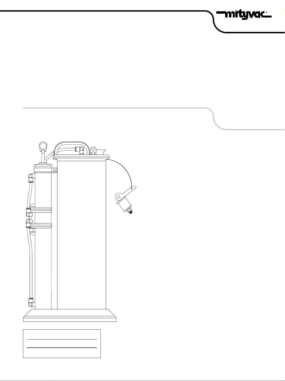
Model MV7201
Fluid evacuator plus
Date of issue November 2017
Form number 801672
Version 2

DANGER
Do not use with gasoline, diesel,
kerosene or 2 stroke mixture.
Failure to comply may result in death
or serious injury.
Safety
Read and carefully observe operating
instructions before unpacking and operating
pump. Pump must be operated, maintained
and repaired exclusively by persons familiar
with operating instructions. Local safety
regulations regarding installation, operation
and maintenance must be followed.
Operate pump only after safety
instructions and this service manual are
fully understood.
Explanation of signal
words for safety
Contents
Safety . . . . . . . . . . . . . . . . . . . . . . . . . . . 2
Explanation of signal words for safety . . 2
Precaution . . . . . . . . . . . . . . . . . . . . . . . 3
Automatic shut-off valve . . . . . . . . . . . . 3
Reservoir specifications . . . . . . . . . . . . . 3
Extract from and dispense
motor oil into crankcase. . . . . . . . . . . . 3
Extract from and dispense
fluid into transmission cases
and differentials . . . . . . . . . . . . . . . . . . 4
Extract and dispense
coolant into cooling system . . . . . . . . . 5
Extract brake fluid from
master cylinder . . . . . . . . . . . . . . . . . . . 5
Technical questions. . . . . . . . . . . . . . . . . 5
Service parts. . . . . . . . . . . . . . . . . . . . . . 5
Illustrated parts break down. . . . . . . . . . 6
Model MV7201 service parts list . . . . . . 6
NOTE
Emphasizes useful hints and
recommendations as well as
information for efficient and trouble-
free operation.
CAUTION
Indicates a dangerous situation that can lead
to light personal injury or property damage if
precautionary measures are ignored.
WARNING
Indicates a dangerous situation that can lead
to death or serious injury if precautionary
measures are ignored.
DANGER
Indicates a dangerous situation that will lead
to death or serious injury if precautionary
measures are ignored.
2

Precaution
Equipment is designed for servicing a variety
of vehicles in a safe and convenient manner;
however, differences in engine blocks and
dip stick configurations make it impossible to
use equipment on every vehicle.
Documented procedures are to serve as
guidelines for general use of equipment. In
addition to guidelines, always follow
manufacturer’s recommended procedures
when attempting to use equipment on each
unique vehicle.
Do not attempt to force tubes included
with equipment into dip stick tube that does
not readily accept smaller of two tubes.
Tubes that appear to be too large are not
designed to be used with these particular
vehicles.
Draining oil with evacuator unit through
dipstick tube is expected to be simple and
straightforward. Instructions are written as a
general guideline only. Always read carefully
and understand instructions prior to
using equipment.
Tighten lid-to-reservoir screws before
first use, and periodically after, to ensure
proper seal.
Automatic shut-off valve
Reservoir tank of fluid evacuator plus is
equipped with automatic shut-off valve to
prevent over-filling of reservoir tank. As fluid
flows into reservoir tank, float raises. When
float reaches shut-off valve, flow of fluid
being extracted automatically stops.
While automatic shut-off is in place it is
not guaranteed to prevent overfill. Make sure
the extractor is on a level surface and take
caution to not overfill the unit.
WARNING
Do not adjust pressure relief valve.
Build pressure by pumping at pumping rate
of maximum 40 strokes per minute. Unit
should not be pressurized by any other
means.
Failure to comply may result in death or
serious injury
NOTE
Do not force tube into crankcase. Stop
inserting tube in if any force is recognized.
Dealer should be contacted for detail on
using equipment to evacuate oil from vehicle
if issues arise.
Extract from and
dispense motor oil
into crankcase
1 Park vehicle on level ground.
2 Ensure transmission of vehicle is in
neutral or park and apply parking brake.
3 Start engine.
4 Allow engine to idle until it reaches
normal operating temperature. Once
this is accomplished, turn engine off.
NOTE
It may be necessary to empty fluid reservoir
tank and restart process if crankcase capacity
exceeds 8 liters (2.11 gallons).
Table 1
Reservoir specifications
Capacity 2.3 gallons (8,8 liters)
Maximum operating
temperature
175 °F (80 °C)
Recommended fluids Engine oil, gear and
transmission oils,
power steering fluid,
coolants, brake fluid,
and other similar fluids
NOTE
Verify tube is in connector all the way to
prevent leakage.
5 Remove engine oil dipstick.
6 Select and insert smallest diameter
dipstick tube into dipstick hole until it
reaches bottom of oil pan.
7 Connect main suction tube to
dipstick tube.
8 Insert opposite end of main suction tube
into 10mm x 90° tube connector on top
of reservoir tank.
NOTE
Do not extract oil when temperature is above
176 °F (80 °C).
9 Place selector valve mounted on side of
pump assembly to evacuate.
10 Raise pump handle on reservoir tank
until highest limit is reached.
11 Pump handle approximately ten times.
Unit will begin to extract oil from engine
crankcase.
3

12 Once oil is extracted from crankcase,
remove expandable rubber plug from
reservoir tank.
13 Pour oil from tank into suitable
container, and dispose of oil in
appropriate manner.
14 Rinse out reservoir tank with clean
solvent or engine degreaser. Allow to dry
thoroughly.
15 If using fluid evacuator plus to dispense
oil, fill cleaned reservoir tank with new oil
and switch selector valve mounted on
side of pump assembly to dispense.
16 Pull up on pump handle and begin
pumping until engine crankcase is filled
to desired level.
17 Run engine momentarily to circulate
new oil and then re-check level.
4 Connect main suction tube to
dipstick tube.
5 Insert opposite end of main
suction tube into 10mm x 90° tube
connector on top of reservoir tank.
WARNING
In some applications this may require jacking
or lifting vehicle. Use appropriate safety
stands to avoid serious or fatal injury.
6 Place selector valve mounted on side of
pump assembly to evacuate.
7 Raise pump handle on reservoir tank
until highest limit is reached. Pump
handle approximately ten times. Unit will
begin to extract transmission fluid from
transmission.
8 Once transmission fluid has been
extracted, remove expandable
rubber plug from reservoir tank.
9 Pour transmission fluid from tank into
suitable container, and dispose of
transmission fluid in an
appropriate manner.
10 Rinse out reservoir tank with clean
solvent or engine degreaser. Allow to dry
thoroughly.
11 If using fluid evacuator plus to dispense
transmission fluid, fill cleaned reservoir
tank with new transmission fluid and
simply switch selector valve mounted on
the side of pump assembly to dispense.
12 Pull up on pump handle and continue
pumping until the transmission is filled
to the desired level.
13 Follow operating instructions for vehicle
to properly check transmission fluid level.
Extract from and
dispense fluid into
transmission cases
and differentials
1 Follow steps 1 and 2 above in Extract and
dispense motor oil into a crankcase.
2 Remove transmission fluid dipstick or
fill plug.
3 Select and insert appropriate
diameter dipstick tube into dipstick fill
hole until it reaches bottom of
transmission pan or gear case.
NOTE
Verify tube is in connector all the way to
prevent leakage.
4
Extract brake fluid
from master cylinder
1 Clean exterior of master cylinder and
master cylinder cap.This will prevent dirt
from entering master cylinder reservoir
when cap is removed.
2 Remove lid of master cylinder reservoir.
3 Select appropriate dipstick tube and
connect it to main suction tube.
WARNING
Never remove cap from radiator or expansion
tank while engine is at operating
temperature. Always allow engine to cool
before removing radiator cap or expansion
tank cap. Cooling system is under pressure.
Failure to allow engine to cool before
attempting to remove cap could result in
death or serious injury. WARNING
Prior to inserting extraction tube into master
cylinder reservoir, be sure extraction tube is
clean and free of any other types of fluid.
Failure to do so would result in
contamination of brake fluid in hydraulic
system and cause potential brake failure.
Extract and dispense
coolant into cooling
system
1 Allow engine to cool.
2 Remove radiator/expansion tank cap.
3 Select largest diameter dipstick tube and
insert tube into radiator neck or
expansion tank.
4 Insert opposite end of main suction tube
into 10 mm x 90° tube connector on top
of reservoir tank.
4 Insert opposite end of main suction tube
into 10mm x 90° tube connector on top
of reservoir tank.
Technical questions
If you have questions, or require technical
service, please contact trained service
technicians at: 1-314-679-4200 ext. 4782.
Visit website www.mityvac.com for new
products, catalogs and instructions for
product use.
Service parts
To order replacement or service parts, visit
www.mityvacparts.com or call toll free
1-800-992-9898.
NOTE
Verify tube is in connector all the way to
prevent leakage.
5 Place selector valve mounted on side of
pump assembly to evacuate.
6 Raise pump handle on reservoir tank
until highest limit is reached. Pump
handle approximately ten times. Unit will
begin to extract coolant from
cooling system.
7 Once coolant has been extracted,
remove expandable rubber plug from
reservoir tank.
8 Pour coolant from tank into suitable
container, and dispose of it in
appropriate manner.
9 Rinse out reservoir tank with clean
solvent or engine degreaser. Allow to dry
thoroughly.
10 If using fluid evacuator plus, fill cleaned
reservoir tank with new coolant and
switch selector valve mounted on side of
pump assembly to dispense.
11 Pull up on pump handle and continue
pumping until cooling system is filled to
desired level.
12 Be sure to run engine until it reaches
operating temperature to circulate new
coolant and then re-check level to verify
it is full.
NOTE
Verify tube is in connector all the way to
prevent leakage.
5 Place selector valve mounted on side of
pump assembly to evacuate.
6 Insert end of extraction tube into master
cylinder reservoir.
7 Raise pump handle on reservoir tank
until highest limit is reached.
8 Pump handle approximately ten times.
Unit will begin to extract brake fluid from
master cylinder reservoir.
9 Once break fluid has been extracted,
remove expandable rubber plug from
reservoir tank.
10 Pour break fluid from tank into suitable
container and dispose of it in
appropriate manner.
11 Rinse out reservoir tank with clean
solvent or engine degreaser. Allow to
dry thoroughly.
12 After all repairs are accomplished, refill
system with new, manufacturer approved
brake fluid from sealed container.
5
4
10
10
12
9
7
2
8
1
4
4
5
11
3
3
13
4
12
9.25 in
(125, 7 mm)
12.38 in
(314,4 mm)
6
23.92 in
(607,5 mm)
1)
2)
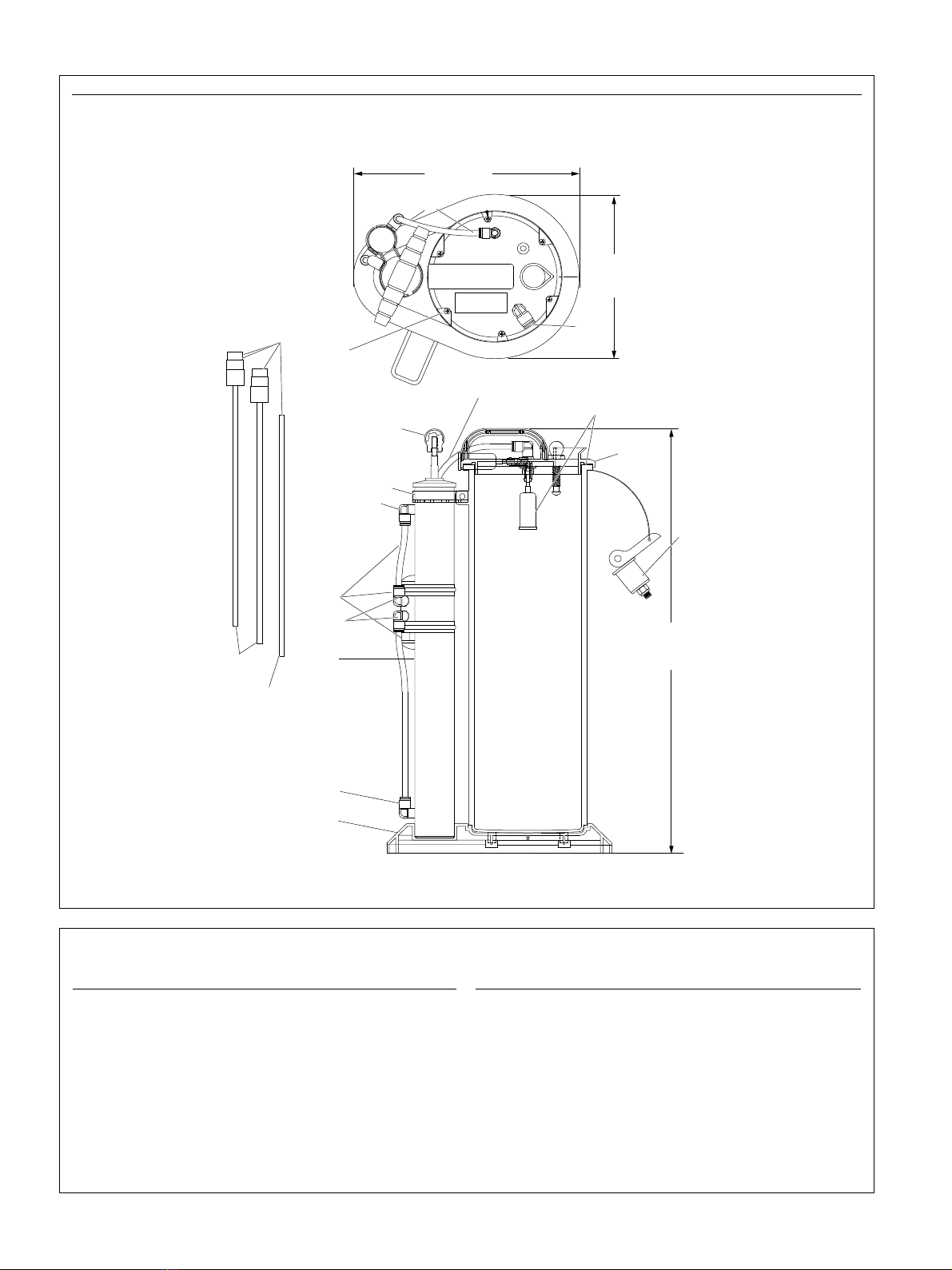
Model MV7201 service parts list
Item Description Part no. Item Description Part no.
1Vacuum tube kit 822559 7 Evacuator top kit 5) 822576
2Handle kit 822561 8 Pump strap kit 822578
3Valve kit 1) 822563 9 Expandable plug kit 822593
4Tube connector kit 2) 822566 10 Top seal kit 822821
5Pump assembly kit 3) 822572 11 Tube connector with check kit 822998
6Base kit 4) 822574 12 Field service kit 6) MVM9000
13 Replacement tube 801671
1) Consists of three tubes, three 8 mm connectors and valve.
2) Consists of three 8 mm connectors and three 10 mm connectors.
3) Consists of two 8 mm connectors, two tubes and pump assembly.
4) Consists of base and foot bracket.
5) Consists of top and overfill float.
6) Consists of top seal, six locknuts, 10 mm connector, and six M5 screws.
1) Dipstick tubes.
2) Main suction tube.
Fig. IPB 1
6

This page left intentionally blank.
7

skf.com | mityvac.com
® SKF and MityVac are registered trademarks of the SKF Group.
© SKF Group 2017
The contents of this publication are the copyright of the publisher and may not be reproduced (even
extracts) unless prior written permission is granted. Every care has been taken to ensure the accuracy
of the information contained in this publication but no liability can be accepted for any loss or damage
whether direct, indirect or consequential arising out of the use of the information contained herein.
November 2017 · Form 801672 Version 2
Table of contents
Other SKF Water Pump manuals

SKF
SKF RA User manual

SKF
SKF PAB Series User manual

SKF
SKF LINCOLN FlowMaster II A Series User manual

SKF
SKF MSU Series User manual

SKF
SKF SKF-MPB-PUMP-1/1 User manual

SKF
SKF 40PGA User manual

SKF
SKF Lincoln HTL 201 User manual

SKF
SKF THAP 030E User manual

SKF
SKF KFGL User manual

SKF
SKF LINCOLN P203 User manual


Popular Water Pump manuals by other brands


Kärcher
Kärcher BP 3 manual

Proeco
Proeco 1051 Assembly instructions

SunSun
SunSun SuperEco JTP Series Operation manual

PSG Dover
PSG Dover WILDEN PRO-FLO P8 Engineering, operation & maintenance

Fristam Pumps
Fristam Pumps FPM Series English translation of the original German Operating Manual

RIDGID
RIDGID RSS-1000 Operating instructions and parts manual