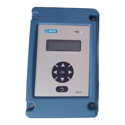
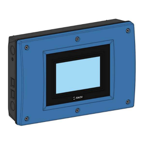
Skov DOL 278 User manual

DOL 278 ON/OFF
DOL 278 ON/OFF-styret nødopluk
Teknisk manual
DOL 278 ON/OFF Controlled
Emergency Opening
Technical manual
DOL 278 ON/OFF gesteuerte
Notöffnung
Technisches Handbuch


Teknisk manual 3
DOL 278 ON/OFF
Version
Frigivelsen fandt sted i 2014.
Produkt- og dokumentationsrevision
SKOV A/S forbeholder sig ret til at ændre denne manual og produktet beskrevet i den uden forudgående meddelelse. I
tvivlstilfælde bedes De rette henvendelse til SKOV A/S.
Seneste revision af denne manual fremgår af bagsidens datomærkning.
Bemærk
•Alle rettigheder tilhører SKOV A/S. Det er ikke tilladt at reproducere denne manual eller dele af den uden
skriftlig tilladelse fra SKOV A/S.
•Alle anstrengelser er gjort for at sikre at indholdet i denne manual er korrekt. Hvis der på trods af dette skulle
opdages fejl eller upræcis oplysning, vil SKOV A/S sætte stor pris på at blive informeret herom.
•Uanset ovenstående kan SKOV A/S ikke påtage sig ansvaret for fejl i denne manual eller for eventuelle følger
heraf.
•Copyright 2014 by SKOV A/S.
Version
It was released in 2014.
Product and Documentation Changes
SKOV A/S reserve the right to change this manual and the product described herein without further notice. In case of doubt,
please contact SKOV A/S.
Latest date of change appears from the back page.
Note
•All rights reserved. No part of this manual may be reproduced in any manner whatsoever without the expressed
written permission of SKOV A/S in each case.
•SKOV A/S have made reasonable efforts to ensure the accuracy of the information contained in this manual.
Should any mistakes or imprecise information occur in spite of this, SKOV A/S would appreciate being notified
thereof.
•Irrespective of the above, SKOV A/S shall not have any liability with respect to loss or damage caused or
alleged to be caused by reliance on any information contained herein.
•Copyright 2014 by SKOV A/S.
Version
Freigegeben im 2014.
Produkt- und Dokumentationsaktualisierung
SKOV A/S behält sich das Recht vor, ohne vorherige Mitteilung, dieses Dokument und das hierin beschriebene Produkt zu
ändern. Bitte wenden Sie sich im Zweifelsfall an SKOV A/S.
Das Aktualisierungsdatum dieses Handbuchs ist aus dem Datumsaufdruck auf der Rückseite ersichtlich.
Achtung
•SKOV A/S behält sich alle Rechte vor. Die Vervielfältigung dieses Handbuchs oder von Teilen des Handbuchs
ist ohne die vorherige, schriftliche Zulassung von SKOV A/S unzulässig.
•SKOV A/S hat alles unternommen, um sicherzustellen, dass der Inhalt dieses Handbuchs korrekt ist. Sollten
trotzdem Fehler oder Ungenauigkeiten auftreten, wäre Ihnen SKOV A/S für eine diesbezügliche Mitteilung sehr
dankbar.
•Ungeachtet dessen schließt SKOV A/S jede Haftung für jede Art Fehler in diesem Handbuch bzw. deren Folgen
aus.
•Copyright 2014 by SKOV A/S.

4 Teknisk manual
DOL 278 ON/OFF
DANSK 6
1Produktbeskrivelse..............................................................................................6
2Arbejdsgang.....................................................................................................6
3Kontrol af dele......................................................................................................6
4Montagevejledning ..............................................................................................7
5Installationsvejledning........................................................................................7
5.1 Elektrisk tilslutning .......................................................................................................... 7
5.2 Installation af batteri i DOL 278 ..................................................................................... 8
5.3 Tilslutning af kabler ......................................................................................................... 8
5.4 Installation af TEST- forsyningsadskiller netafbryderen ved DOL 278 ..................... 8
5.5 Indstilling af netspænding................................................................................................ 8
5.6 Tilslutning i klimacomputeren ........................................................................................ 9
5.6.1 Eldiagram –DOL 278 medium .......................................................................................... 9
5.6.2 Eldiagram –DOL 278 large.............................................................................................. 10
5.6.3 Indstilling af klimacomputer............................................................................................. 11
6Afprøvning..........................................................................................................11
6.1 Test af installationen....................................................................................................... 11
7Fejlfindingsvejledning.......................................................................................12
8Tekniske data.....................................................................................................13
ENGLISH 14
1Product Description ..........................................................................................14
2Procedure......................................................................................................14
3Checking the Parts ............................................................................................14
4Mounting Guide .................................................................................................15
5Installation Guide...............................................................................................15
5.1 Electric Connection......................................................................................................... 15
5.2 Installation of Battery in DOL 278................................................................................ 16
5.3 Connection of Cables...................................................................................................... 16
5.4 Installation of the TEST Mains Switch at DOL 278.................................................... 16
5.5 Setting the Mains Voltage .............................................................................................. 16
5.6 Connection to the Climate Computer ........................................................................... 17
5.6.1 Wiring Diagram –DOL 278 Medium .............................................................................. 17
5.6.2 Wiring Diagram –DOL 278 Large................................................................................... 18
5.6.3 Setting of the Cllimate Computer ..................................................................................... 19
6Testing................................................................................................................19
6.1 Testing the Installation................................................................................................... 19
7Trouble Shooting Instructions .........................................................................20
8Technical Data ...................................................................................................21
DEUTCH 22
1Produktbeschreibung........................................................................................22

Teknisk manual 5
DOL 278 ON/OFF
2Reihenfolge von Aufbau und Einrichtung..................................................22
3Kontrolle der Teile .............................................................................................22
4Montageanleitung..............................................................................................23
5Installationsanleitung........................................................................................23
5.1 Elektrischer Anschluss................................................................................................... 23
5.2 Installation der Batterie in den DOL 278..................................................................... 24
5.3 Anschluss der Kabel ....................................................................................................... 24
5.4 Einbau des TEST-Netzschalters bei DOL 278 ............................................................. 24
5.5 Einstellung der Netzspannung....................................................................................... 24
5.6 Anschluss von der Klimacomputer ............................................................................... 25
5.6.1 Schaltplan –DOL 278 Medium........................................................................................ 25
5.6.2 Schaltplan –DOL 278 Large............................................................................................ 26
5.6.3 Einstellung von der Klimacomputer................................................................................. 27
5.6.4 Klimacompute Aktive Funktionen bei Stromausfall ........................................................ 27
6Test .....................................................................................................................27
6.1 Test der Installation........................................................................................................ 27
7Fehlersucheanleitung........................................................................................28
8Technische Daten..............................................................................................29

6 Teknisk manual
DOL 278 ON/OFF
DANSK
1 Produktbeskrivelse
Denne manual omhandler montage, installation og igangsætning af et DOL 278 ON/OFF-styret
nødopluksanlæg. For oplysninger om daglig brug af anlægget, se DOL 278 ON/OFF brugermanual.
DOL 278 ON/OFF er en enkel nødopluksenhed, som sammen med klimacomputeren kan nødåbne ved
enkelte fejltyper. Ved nødåbning åbnes helt. Der fås ikke nødopluk for alle slags styringssvigt.
DOL 278 ON/OFF har indbygget 24V-DC motorstrømforsyning, batteri og lader.
Findes i flg. varianter:
•DOL 278 ON/OFF, medium (4,2A)
•DOL 278 ON/OFF, large (8A)
2 Arbejdsgang
1. Kontrol af dele
2. Montage
□DOL 278
3. Installation
□Batteri
□TEST- netafbryder forsyningsadskiller
□Tilslutning af kabler
□Indstilling af netspænding
□Tilslutning til klimacomputer
□Tilslutning af netspænding
□Indstilling af klimacomputer
4. Afprøvning
□DOL 278
□Batteri
5. Opstart
3 Kontrol af dele
Kontroller at følgende dele til alarmanlægget er til stede:
Figur
Antal
Beskrivelse
1
DOL 278 ON/OFF nødopluk
1
Manualpakke
1
Gummitylle

Teknisk manual 7
DOL 278 ON/OFF
4 Montagevejledning
1) Prik/bor huller i bunden af kabinettet (A).
2) Placer DOL 278:
•så tæt på klimacomputeren, at medfølgende gummimuffe (B) kan nå imellem dem
(DOL 278 kan placeres på begge sider af klimacomputeren).
•at der er plads, især over DOL 278, til servicestilling (C) af låget.
3) Bank store udslagsbrikker (D) ud af klimacomputeren og DOL 278 og monter gummimuffen i
ét af hullerne.
4) Fastskru DOL 278 med Ø5 skruer og evt. Ø8 murplugs (E), så gummimuffen klemmes ca. 10
mm.
5) Monter gummimuffen (B) vandtæt.
6) Før kablerne igennem gummimuffen.
Er der ikke plads lige ved siden af klimacomputeren, kan gummimuffen undlades, kablerne forlænges
og føres igennem M25-kabelforskruninger (F).
Figur 1: Montering af DOL 278
5 Installationsvejledning
5.1 Elektrisk tilslutning
Installationen, service og fejlfinding af elektrisk udstyr skal foretages af sagkyndigt
personale i henhold til gældende nationale regler, - i Europa efter EN 60204-1 og øvrige
gældende EU-regler.
Forsyningsadskiller skal monteres for hver strømforsyning, så arbejde på det elektriske
udstyr kan foregå spændingsløst. Forsyningsadskiller leveres ikke af SKOV A/S.
( C )
( A )
( E )( D )( F ) ( B )
ON/OFF

8 Teknisk manual
DOL 278 ON/OFF
For at opnå størst mulig sikkerhed i en nødsituation, må DOL 278AT ikke forsyne andre
produkter med 24 V DC spænding end de af SKOV A/S anviste produkter. Sker dette, vil
eventuelle følger være for egen risiko.
5.2 Installation af batteri i DOL 278
Batterimodul 4Ah til DOL 278 medium
Afkryds og påklæb medfølgende batteri-datomærkat
udvendigt på DOL 278 kabinettet.
Anbring batteriet på hylden i DOL 278 kabinettet og spænd
det fast med medfølgende kabelbinder som vist.
Batterimodul 7Ah til DOL 278 large
Batteriet skal IKKE tilsluttes endnu.
Se Figur 3 (F).
5.3 Tilslutning af kabler
Der skal anvendes armeret installationskabel af hensyn til gnavere, minimum 1,0 mm2(230 V)
Ved 24 V forsyning skal som minimum anvendes 1,5 mm2kabel, for at sikre lavt spændingstab til
spjældmotorerne ved 18 V batteridrift.
5.4 Installation af TEST- forsyningsadskiller netafbryderen
ved DOL 278
Placer forsyningsadskiller netafbryderen til TEST ved side af DOL 278 og klimacomputeren til
ugentlig test af nødoplukket.
Forsyningsadskiller Netafbryderen skal være 2-polet, hvis to-staldscomputeren forsynes fra hver deres
fase. Forsyningsadskiller Netafbrydere kan være 3-polet ved flere klimacomputere på samme DOL
278.
5.5 Indstilling af netspænding
Indstil netspændingen til områdets normale netspænding 115, 200/ eller 230/240 V på
netspændingsvælgeren. Fabriksindstilling = 230/240 V.
DOL 278 LARGE: Netspændingen skal indstilles på to
moduler.

Teknisk manual 9
DOL 278 ON/OFF
5.6 Tilslutning i klimacomputeren
5.6.1 Eldiagram –DOL 278 medium
Q21 Q32
Q22 Q23 Q24 Q25 Q26 Q27 Q28 Q29 Q30 Q31
N
N L1
L1
L2
L2
Q1 Q2 Q3 Q4 Q5
0V +24V +24V +24V +24V
1 1 2 2
No. No. No. No.
No.
+ +
+
+
+
C5C2 C4 C7 C9C8C6C1 C3 15 C16 C17 C18 C19 C20 C21 C22
+15V
0-10V
0-10V
DOL12
1
0-10V
0-10V
OUTDOOR
2
0-10V
10V
0-10V
10V 24V
DOL12
A4
A1 A2
LN
230-240V
3+115/200
230/240V~
10A
N
L1
L2
0V
0V
M
+ +
M
0V
0V
MM
DOL 278
Klimacomputer

10 Teknisk manual
DOL 278 ON/OFF
5.6.2 Eldiagram –DOL 278 large
No. No. No. No.
No.
Q1 Q2 Q3 Q4 Q5
0V +24V +24V +24V +24V
1 1 2 2
+ +
+
+
+
0V
0V
M
+ +
M
0V
0V
A1 A6
A2 A4 A5
L N _+
24V
115-200
-230 240V~
A4
A1 A2
LN
230-240V
3+115/200
230/240V~
10A
N
L1
L2
Q21 Q32
Q22 Q23 Q24 Q25 Q26 Q27 Q28 Q29 Q30 Q31
N
N L1
L1
L2
L2
C5C2 C4 C7 C9C8C6C1 C3 15 C16 C17 C18 C19 C20 C21 C22
+15V
0-10V
0-10V
DOL12
1
0-10V
0-10V
OUTDOOR
2
0-10V
10V
0-10V
10V 24V
DOL12
MM
DOL 278
Klimacomputer

Teknisk manual 11
DOL 278 ON/OFF
5.6.3 Indstilling af klimacomputer
5.6.3.1 Klimacomputer aktive funktioner ved styringssvigt
Ved installation af MultiStep luftudtag og højtrykskøling skal du tage stilling til, hvordan disse
funktioner skal reagere i en nødsituation, se teknisk manual for klimacomputer.
MultiStep luftudtag
Ja: Ved styringssvigt er luftudtaget aktivt.
Nej: Ved styringssvigt er luftudtaget ikke aktivt.
Højtrykskøling
JA: Ved styringssvigt er højtrykskøling aktiv og kører indtil nødsituationen er afsluttet.
Nej: Ved styringssvigt er højtrykskøling ikke aktiv.
6 Afprøvning
6.1 Test af installationen
Udfør testen når det ikke er så varmt, at ventilationsanlægget allerede er helt åbent. Ventilerne skal
være lukket.
Batteriet skal oplades mindst 10 minutter inden første afprøvning.
1) Tilslut panel/låg og netspænding (115, 200 eller 230 V) på fælles ekstern TEST-
forsyningsadskiller netafbryder for DOL 278 nødopluk og klimacomputer.
Batterilampen i låget skal lyse grønt.
2) Tilslut batteriledninger. Rød ledning til rødt batteristik og sort til sort batteristik.
Batterilampen skal fortsat lyse grønt.
3) Afbryd netspænding (115, 200 eller 230 V) til DOL 278 nødopluk og klimacomputer.
Batterilampen skal fortsat lyse grønt, imens anlægget åbner helt.
Ved 2-stalds klimacomputer åbnes anlægget automatisk samtidig i begge stalde.
Grøn batterilampe skal lyse under hele åbningen, som tegn på at batteriet er i orden og
opladt.
Hvis lampen ikke lyser:
oEr batteriet afladt < 16 V.
oEr blå 15 A bilsikring sprunget.
oEller er batteriledning glemt.
4) Tilslut netspænding (115, 200 eller 230 V) til DOL 278 nødopluk og klimacomputer igen.
Anlægget skal lukke tilbage til udgangspositionen, når klimacomputeren er kommet i gang
igen.
Grøn batterilampe skal fortsat lyse grønt.
Ventilationsanlægget skal mindst kunne åbnes to gange efter hinanden på et fuldt opladt nyt batteri.

12 Teknisk manual
DOL 278 ON/OFF
7 Fejlfindingsvejledning
Spjældmotor vil ikke køre:
Er der netspænding på klemme F1 og F2?
Hvis ikke så kontroller:
- ekstern TEST- forsyningsadskiller netafbryder
- netspændingsvælger
- installationssikringer
- fejlstrømsrelæ
- spjældmotors AUT-MAN omskifter
- ledning til motorlåg
Batteri-lampe lyser ikke, selvom netspændingen er i orden:
Er der ca. 24 V DC på klemme F5-F6?
Hvis ikke så kontroller:
- panelledning
- ekstern 24 V installation på F5-F6
Batteri-lampe lyser ikke ved afbrudt netspænding (batteridrift):
Er der ca. 18 V DC på klemme F5-F6?
Hvis ikke så kontroller:
- batteriledninger
- panelledning
- sikringer (reservesikringer)
- spænding på batteri
Spjældmotor kører ikke ved afbrudt netspænding:
Systemet kræver 24 V DC spjældmotorer. Motorerne skal desuden kunne
åbne ved maksimal belastning ned til 15 V DC, da anlægget arbejder med
18 V batteri. Dette er normalt uproblematisk for almindelige 24 V DC
spjældmotorer.

Teknisk manual 13
DOL 278 ON/OFF
8 Tekniske data
DOL 278 medium
DOL 278 large
Elektrisk
Netspænding
115, 200, 230/240 V AC ± 10 %
Netfrekvens
50/60 Hz
Udgangsspænding netdrift
24 V DC ± 30 %
Udgangsspænding batteridrift
15-18 V DC
Udgangsstrøm maks. kontinuerlig ved netdrift
2,1 A
4 A
Motorstrøm maks.:
4,2 A
8 A
(F.eks. 2 stalde med hver 2,1 A på én DOL 278. Samtidig motordrift i begge stalde tillades i maks. 20 % af tiden
og 10 minutter ad gangen).
(F.eks. 1 stald med 4,2 A på én DOL 278. Motordrift tillades i maks. 20 % af tiden og 10 minutter ad gangen).
Batteri standby ladespænding
20,5 V
Batteri ladestrøm maks.
1,5 A
Batteri sikring (blå bilsikring med spadestik)
15 A
Batteri-lampe OK niveau
>16 V
Batterimodul, gastæt bly
18 V 4 Ah (3 x 6 V 4 Ah)
18 V 7Ah
Mekanisk
Kabeludslagshuller
12 stk. kabelforskruning M25×1,5
Miljø
Temperatur, drift
- 10 °C + 45 °C
Temperatur, lager
- 25 °C + 60 °C
Tæthedsklasse
IP 54
Det forudsættes at underlaget er plant, dvs. ≤ 1,5 mm
højdeforskel, og at lågets skruer fastspændes med min.
200 Ncm
EMC-immunitet
EN 50081-2 Industri
EMC-emission
EN 50082-2 Industri
Forsendelse
Mål DOL 278
H x B x D: 381 x 400 x 170 mm
Mål DOL 278 emballeret
H x B x D: 425 x 555 x 195 mm
Forsendelsesvægt DOL 278 medium
9,5 kg
7,5 kg*
Forsendelsesvægt eksternt pakket batteri til DOL 278 large
3,5 kg

14 Technical manual
DOL 278 ON/OFF
ENGLISH
1 Product Description
This manual describes the mounting, installation and commissioning of a DOL 278 ON/OFF-
controlled emergency opening system. For information about the day-to-day use of the system, see the
DOL 278 ON/OFF user's manual.
DOL 278 ON/OFF is a simple emergency opening unit, which in combination with the climate
computer can emergency open in case of simple types of error. In case of emergency, the system
opens completely. Emergency opening is not available for all types of control failures.
A 24 V DC motor power supply, battery and charger are incorporated into DOL 278 ON/OFF.
Available in the following variants:
•DOL 278 ON/OFF, medium (4.2A)
•DOL 278 ON/OFF, large (8A)
2 Procedure
1. Checking the parts
2. Mounting
□DOL 278
3. Installation
□Battery
□TEST- supply separator
□Connecting cables
□Setting the mains voltage
□Connection to climate computer
□Connecting mains voltage
□Setting the climate computer
4. Test
□DOL 278
□Battery
5. Start-up
3 Checking the Parts
Check that the following parts for the alarm system are available:
Figure
No.
Description
1
DOL 278 ON/OFF emergency opening unit
1
Manual package
1
Rubber sleeve

Technical manual 15
DOL 278 ON/OFF
4 Mounting Guide
1) Prick/drill holes in the bottom of the cabinet (A).
2) Position DOL 278:
•close enough to the climate computer for the rubber sleeve supplied (B) to fit neatly
between them (DOL 278 can be placed on either side of the climate computer).
•so that there is enough space, particularly above DOL 278, for service setting (C) of the
lid.
3) Knock out large knock-out pieces (D) from the climate computer and DOL 278 and mount the
rubber sleeve in one of the holes.
4) Tighten DOL 278 using Ø5 screws and, if necessary, Ø8 wall plugs (E), so that the rubber
sleeve is squeezed approx. 10 mm.
5) Mount the rubber sleeve (B) so that it is waterproof.
6) Guide the cables through the rubber sleeve.
If space is inadequate right next to the climate computer, the rubber sleeve can be left out, and the
cables can be extended and routed through M25 screwed cable connections (F).
Figure 1: Mounting of DOL 278
5 Installation Guide
5.1 Electric Connection
In order to ensure max. security in case of an emergency situation, DOL 278 must not supply
24 VDC to products other than those stated by SKOV A/S.
If it does, any subsequent consequences will be at the owner’s own risk.
The installation, service and troubleshooting in connection with electrical equipment must be
carried out by specialists in accordance with applicable national rules - in Europe in
accordance with EN 60204-1 and other applicable EU rules.
The installation of a supply isolator is required for each motor and power supply, so
maintenance of electrical equipment can be carried out in a dead environment. Supply
isolator is not supplied by SKOV A/S.
( C )
( A )
( E )( D )( F ) ( B )
ON/OFF

16 Technical manual
DOL 278 ON/OFF
5.2 Installation of Battery in DOL 278
Battery module 4Ah for DOL 278 medium
Tick and attach the supplied battery date label to the outside of
the DOL 278 cabinet.
Place the battery on the shelf in the DOL 278 cabinet and secure
it with the included cable tie as shown.
Battery module 7Ah for DOL 278 large
Do NOT connect the battery yet.
See Figure 3 (F).
5.3 Connection of Cables
Use a minimum of 1.0 mm2armoured cable for 230V (because of rodents) to connect up the unit.
For 24V supply, as a minimum use 1.5 mm2cable to ensure a low loss of voltage for the winch motors
at 18V battery operation.
5.4 Installation of the TEST supply separator at DOL 278
Position the TEST supply separator next to DOL 278 and the climate computer for weekly testing of
the emergency opening.
Use a double pole switch if two separate phases are being used with the two house computers or a
three phase switch if other units are being connected.
5.5 Setting the Mains Voltage
The mains voltage switch MUST be set to the correct local supply setting of 115, 200/ or 230/240V at
switch. Factory setting is 230/240V AC.
DOL 278 LARGE: Mains voltage must be set on two
modules.

Technical manual 17
DOL 278 ON/OFF
5.6 Connection to the Climate Computer
5.6.1 Wiring Diagram –DOL 278 Medium
Q21 Q32
Q22 Q23 Q24 Q25 Q26 Q27 Q28 Q29 Q30 Q31
N
N L1
L1
L2
L2
Q1 Q2 Q3 Q4 Q5
0V +24V +24V +24V +24V
1 1 2 2
No. No. No. No.
No.
+ +
+
+
+
C5C2 C4 C7 C9C8C6C1 C3 15 C16 C17 C18 C19 C20 C21 C22
+15V
0-10V
0-10V
DOL12
1
0-10V
0-10V
OUTDOOR
2
0-10V
10V
0-10V
10V 24V
DOL12
A4
A1 A2
LN
230-240V
3+115/200
230/240V~
10A
N
L1
L2
0V
0V
M
+ +
M
0V
0V
MM
DOL 278
Climate computer

18 Technical manual
DOL 278 ON/OFF
5.6.2 Wiring Diagram –DOL 278 Large
No. No. No. No.
No.
Q1 Q2 Q3 Q4 Q5
0V +24V +24V +24V +24V
1 1 2 2
+ +
+
+
+
0V
0V
M
+ +
M
0V
0V
A1 A6
A2 A4 A5
L N _+
24V
115-200
-230 240V~
A4
A1 A2
LN
230-240V
3+115/200
230/240V~
10A
N
L1
L2
Q21 Q32
Q22 Q23 Q24 Q25 Q26 Q27 Q28 Q29 Q30 Q31
N
N L1
L1
L2
L2
C5C2 C4 C7 C9C8C6C1 C3 15 C16 C17 C18 C19 C20 C21 C22
+15V
0-10V
0-10V
DOL12
1
0-10V
0-10V
OUTDOOR
2
0-10V
10V
0-10V
10V 24V
DOL12
MM
DOL 278
Climate computer

Technical manual 19
DOL 278 ON/OFF
5.6.3 Setting of the Cllimate Computer
5.6.3.1 Climate computer Active Functions when the Control Fails
When installing MultiStep air outlets and high-pressure cooling, you must decide how these functions
are to react in an emergency situation, see technical manual for climate computer.
MultiStep air outlet
Yes: When the control fails, the air outlet is active.
No: When the control fails, the air outlet is not active.
Spray cooling
Yes: When the control fails, spray cooling is active and runs until the emergency situation is
over.
No: When the control fails, spray cooling is not active.
6 Testing
6.1 Testing the Installation
Test when it is not so hot that the ventilation system has already opened completely. The inlets must
be closed.
Charge the battery for at least 10 minutes before the first test.
1) Connect the panel/lid and mains voltage using the common external TEST supply separator
for the DOL 278 emergency opening and climate computer.
The battery light in the front panel should be green.
2) Connect the battery wires. Red battery wire to red battery connector and black wire to black
battery connector.
The battery light should still be green.
3) Disconnect the mains voltage for the DOL 278 emergency opening and climate computer.
The battery light should still be green while the system opens completely.
For two-house climate computers, the system opens automatically at the same time in both
houses.
The green battery light must be on during the entire opening sequence to show that
the battery is in order and charged.
If the light is not on:
oThe battery has been discharged < 16 V.
oThe blue 15 A car fuse has been blown.
oOr the battery wire has been forgotten.
4) Reconnect the mains voltage for the DOL 278 emergency opening and climate computer.
The system must close back to its initial position when the climate computer has started
again.
The battery light should still be green.
A new fully charged battery should at least be able to open the ventilation system two consecutive
times.

20 Technical manual
DOL 278 ON/OFF
7 Trouble Shooting Instructions
Winch motor will not run:
Is mains voltage supplied to terminals F1 and F2?
If not, check:
- external TEST supply separator
- mains voltage selector
- installation fuses
- fault current relay
- AUT-MAN switch of the winch motor
- wire connection to motor lid
Battery lamp is not lit, in spite of OK mains voltage:
Is there approx. 24V DC on terminals F5-F6?
If not, check:
- panel wire connection
- external 24V installation on F5-F6
Battery lamp not lit by uninterrupted 230V (battery operation):
Is approx. 18V DC supplied to terminals F5-F6?
If not, check:
- battery wires
- panel wire
- fuses (spare fuses)
- battery voltage.
Winch motor is not running when mains voltage is disconnected:
The system requires 24V DC winch motors. Furthermore, the motors must
be able to open at maximum load as low as 15V DC, as the system works
using an 18 V battery. This is not normally a problem for ordinary 24V DC
winch motors.
Other manuals for DOL 278
2
Table of contents
Languages:
Other Skov Controllers manuals
Popular Controllers manuals by other brands

Xylem
Xylem CentriPro Aquavar SOLO instruction manual

esera automation
esera automation 11319 operating instructions

Danfoss
Danfoss AK-SM 800 Quick reference guide

Atlas Copco
Atlas Copco POWER FOCUS 6000 Configuration manual

Victron energy
Victron energy BlueSolar MPPT 150/70 manual

Panasonic
Panasonic FP3 Technical manual