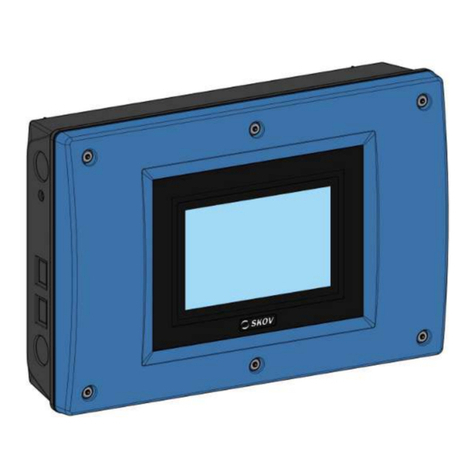
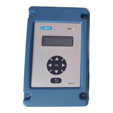
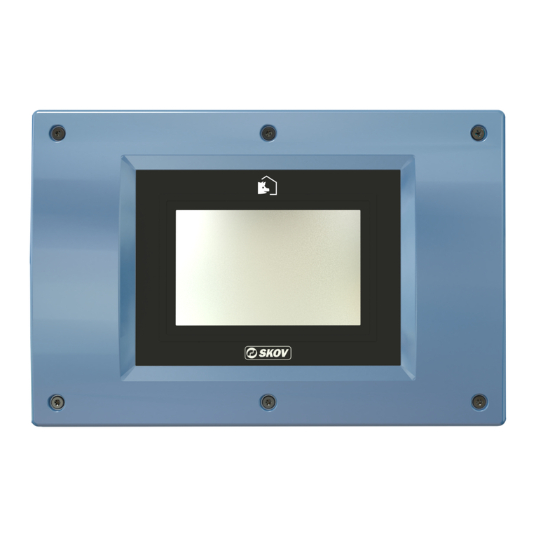
Skov DOL 78CT User manual

605041
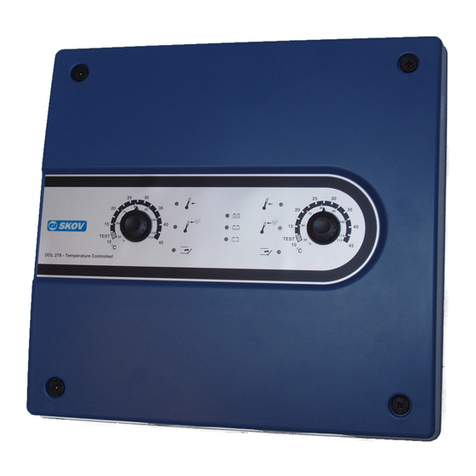
DOL 78CT Combi Tunnel
Emergency opening, temperature controlled 24V DC 4A
x
User’s manual
SKOV A/S. HEDELUND 4, GLYNGØRE. DK-7870 ROSLEV. DENMARK
01.02.99

CONTENTS PAGE
01.02.99 DOL 78CT MANUAL
1
Contents
1. PRODUCT DESCRIPTION..................................................................................................................................2
1.1 THE DOCUMENTATION CONSISTS OF THE FOLLOWING............................................................................................2
2. FUNCTIONS..........................................................................................................................................................3
2.1 BATTERY MONITORING........................................................................................................................................4
2.2 SPECIAL ! EXTENSION OF THE 24V SUPPLY CAPACITY ..........................................................................................4
3. OPERATION.........................................................................................................................................................5
3.1 DAILY OPERATION...............................................................................................................................................5
3.2 WEEKLY TEST.....................................................................................................................................................5
3.3 MAINTENANCE...................................................................................................................................................6
3.3.1 Battery capacity check...............................................................................................................................6
4. INSTALLATION ...................................................................................................................................................7
4.1 ASSEMBLY OF MECHANICAL PARTS.......................................................................................................................7
4.1.1 Opening the DOL 78CT Emergency opening unit.......................................................................................7
4.1.2 Installation of DOL 78CT Emergency opening unit....................................................................................7
4.1.3 Installation of battery in DOL 78CT ..........................................................................................................8
4.1.4 Installation of TEST mains switch..............................................................................................................9
4.1.5 Installation of temperature sensor in the house ..........................................................................................9
4.1.6 Connection of DOL 78CT Emergency Opening and DOL 36CT Climate Computer....................................9
4.1.7 Connection of DOL 78CT Emergency Opening, AR-module and DOL 36CT Climate Computer..............10
4.1.8 Special ! Installation of Extension module and DOL 78M........................................................................11
4.1.9 Wiring diagram:.......................................................................................................................................12
4.2 ELECTRICAL INSTALLATION...............................................................................................................................13
4.2.1 Installation is carried out in the following order......................................................................................13
4.2.2 Setting of IN/OUT-module and AR-module in DOL 36CT climate computer.............................................14
4.2.3 Notes concerning the fig. 4.8 Basic electrical diagram. Connection of climate computer loop terminal
strip..................................................................................................................................................................16
4.3 LIMITATIONS ....................................................................................................................................................16
5. SERVICE .............................................................................................................................................................21
5.1 TROUBLE SHOOTING.........................................................................................................................................21
5.1.1 Table for DOL 12 temperature sensor check.............................................................................................21
5.2 SPARE PARTS .....................................................................................................................................................22
6. TECHNICAL DATA...........................................................................................................................................23

1 PRODUCT DESCRIPTION PAGE 2
01.02.99 DOL 78CT MANUAL
1. PRODUCT DESCRIPTION
1.1 The documentation consists of the following
1. This manual, which is used for installation / service and should be kept in the office.
2. The enclosed user’s instructions in folded cardboard with different languages on the front and the back.
Turn the side with the required language outwards, fold the instructions and mount them under the
opening lid on DOL 78CT, so that it is easily accessible.
DOL 78CT can perform temperature-controlled emergency opening together with the DOL 36CT Cli-
mate computer in case of a power failure or technical malfunction. The emergency opening system pro-
vides optimum safety through the use of a separate circuit, own temperature sensor and manual setting of
the emergencyopening temperature.
The DOL 36CT Climate Computer units have the following auxiliary functions:
x
Automatic display of DOL 78CT’ preset emergency temperature and the Climate Computer unit set
point (= required house temperature), when the emergency temperature is changed and when switches
are made between normal operation and emergency operation.
x
Monitors the batteryvoltage in DOL 78CT.
x
Gives a warning, if the emergency temperature switch is set at a value which is too high.
x
Logs (stores) the last 20 changes and emergency temperature settings as well as the emergency open-
ing start and stop settings.

2 FUNCTIONS PAGE 3
01.02.99 DOL 78CT MANUAL
2. FUNCTIONS
DOL 78CT monitors the house temperature by means of its own temperature sensor. The function of
DOL 78CT is depending on, if we are in Side mode or Tunnel mode.
Side mode:
If the house temperature exceeds the DOL 78CT setting, the side-inlets and eventually swivel shutter initi-
ate temperature-dependent emergency opening.
“Temperature-dependent opening” means that a minor excess temperature results in slow opening, so that
excessive cooling of the house is avoided. A higher excess temperature results in faster opening, when this
is required.
DOL 78CT adjusts the temperature once every 3 minutes. If, for instance, the house temperature reaches
1 degree above the emergency temperature setting knob
, the side-inlets are opened for a few seconds
once every 3 minutes, which corresponds to 40-60 minutes for complete opening by means of the DA 75
winch motor. If the excess temperature is higher, e.g. 6 degrees above the emergency temperature setting
knob
, the side-inlets are opened for several seconds every 3 minutes, which corresponds to 6-10 min-
utes for complete opening by means of the DA 75 winch motor.
DOL 78CT’s built-in battery and charger ensure that the side-inlets also have a temperature-dependent
opening function in case of excess temperature in connection with power failure.
Tunnel mode:
The DOL 78CT will only go to emergency opening in case of power failure, or defect temperature sen-
sors.
This means when running in Tunnel mode the temperature dependent emergency opening is deactivated.
During normal operation DOL 78CT also supplies 24V DC to DOL 36CT, which cannot supply power to
manyor high-powered winch motors, such as DA 75, on their own.

2 FUNCTIONS PAGE 4
01.02.99 DOL 78CT MANUAL
2.1 Battery monitoring
The batteryvoltage and the 15Afuse
onthe charger module
is checked bylowering the charge
voltage for approx. 5 seconds once every3 minutes.
The motor current passes throughthe 7.5Afuses
ofthe connectionmodule during normaloperation.
The batterycapacityand the rest ofthe circuit canonlybe tested in“Weeklytests”. Section3.2.
2.2 Special! Extension ofthe 24V supply capacity
Ifthe totalmotor current exceeds 4.25Athe 24V supplycapacitycanbe increased bysupplementing DOL
78CT witha DOL 78MON/OFF emergencyopening unit and a DOL 78CT Extensionmodule mounted
inDOL 78M.
See fig. 4.5 InstallationofDOL 78CT extensionmodule. The module synchronizes the lowering ofthe
charge voltage inDOL78M withDOL 78CT.
Inthis wayDOL 36CT, whichconstantlymonitor the batteryvoltage, candetect ifthe overall battery
voltage is too low or ifthe 15V fuses ofbothDOL 78 chargers have blownat the same time.
The batteries ofthe two DOL 78 unitsare coupled inparalleland so are the 24V supplyunits, so the dou-
ble current fromthe batteries and the transformers is available.
LIMITATIONS: Ifonlyone ofthe 15Afuses blows, this cannotbemeasured, but bothshare the power
fromthebatteryofoneoftheDOL78 units.
Fig. 2.1 Layout drawing
TEST-lamp, Green.
Emergency operation active Lamp, Red.
Emergency opening Lamp, Yellow.
Temperature setting knob 0-40 oC.
Mains Voltage selector 230 / 240V.
Battery-fuse 15A.
Wall mounting holes.
Relay with Socket.
Motor-fuses 7,5A.
Spare-fuses.
11
TEST mains switch.
12
Operating Panel.
13
Batterypack.
14
Battery shelf.
15
Connection module.
16
Terminal Block.
17
Slide for Users Instruction.
18
Lid for Users Instruction.
At the following pages the numbers
-
18
re-
fers to this figure

3 OPERATION PAGE 5
01.02.99 DOL 78CT MANUAL
3. OPERATION
3.1 Daily operation
Daily operation is also described briefly in the folded set of user’s instructions to be placed under DOL
78CT’ front lid.
18
.
The required emergency temperature, at which emergency opening must take place, is set by means of the
Temperature setting knob
at the front of DOL 78CT.
When the knob is turned, the climate computer display automatically shows the climate computer set point
(required house temperature) as well as the setting of the DOL 78CT emergency temperature switch for a
few seconds. The emergency temperature should be set approx. 4 degrees above the climate computer set
point (required house temperature).
Example:
Set point, house 25.7 oC
Î
Set point, em. open. 30 oC
If the Climate Computer unit is in batch operation, where the house temperature is automatically lowered
slightly every day, the DOL 78CT switch must be adjusted regularly in order to follow the temperature
lowering of the climate computer. If the DOL 78CT emergency temperature is not lowered so that it is
more than 6ohigher than the climate computer set point, the warning “Emergency temperature too high”
will flash in the climate computer display.
3.2 Weekly test
The emergency opening function MUST be tested at least once a week in order to ensure that it is work-
ing properly.
During the warm periods the test must be carried out early in the morning when the side-inlets are not al-
ready completely open, and the curtains are closed.
Side mode:
1. Note the setting ofthe DOL 78CT temperature setting knob
.
2. Be sure the system is in Side mode . The green lamp must be OFF !
If the green lamp is ON, then wait until the evening or morning where it gets colder, and
automatically switches from Tunnel mode to Side mode.
3. Turn the knob
below 10 degrees.
4. Check that the red and yellow lamps are lit.
5. Check that the system opens in the house.
6. Switch of the mains supply to DOL 36CT and DOL 78CT, at the external TEST switch .
7. Check that the system opens completely and that the green TEST lamp
remains on, during the
entire test sequence, indicating that the battery voltage is OK>16V.
8. Switch on the mains supply again and turn the temperature setting knob
back to its original posi-
tion.
9. Check that the system closes properly again.
Tunnel mode:
10. Go to Tunnel mode, by setting the DA 75CT Curtain Opening motor from:
AUT (automatic) to MAN (manually) and press
Ï
. Let the curtains open totally.
11. Repeat above points 6. - 9. once.
12. IMPORTANT:
Set back the DA75CT Motor to AUT (automatic) and 0.
Remember to set DOL 36CT’ clock, as it looses time during power failure.

3 OPERATION PAGE 6
01.02.99 DOL 78CT MANUAL
Setting the DOL 36CT Climate Computer unit clock
1) Press and until display reads e.g.: 1999-12-19 9:45:23
2) Press
@
@
and so [ ] are inserted around e.g. 45 minutes.
3) Set figure by means of and .
4) Press and set the other fields, if necessary.
5) Press
@
@
to conclude the setting.
3.3 Maintenance
The battery module must be replaced at least once every 3 years.
3.3.1 Battery capacity check
The battery capacity can be measured by performing “Weekly tests”several times until the battery can no
longer operate the motors. This is a realistic measure of how many times the battery can perform emer-
gency opening. It should be possible to open the house at least twice with only a short interval by means
of the battery when it is fully charged. A full recharge takes approx. 3 hours.
Year - month - day h : m : s
1999 - 12 - 19 9 : 45 : 23

4 INSTALLATION PAGE 7
01.02.99 DOL 78CT MANUAL
4. INSTALLATION
4.1 Assembly of mechanical parts
Consists of installation of DOL 78CT emergency opening unit, installation of battery in DOL 78CT, in-
stallation of TEST mains disconnector, installation of temperature sensor DOL 12 in the house and instal-
lation of cable tube between the DOL 36CT climate computer and the DOL 78CT.
4.1.1 Opening the DOL 78CT Emergency opening unit
1) Open the lid by lifting it at the bottom.
2) Remove the smooth protective plate. Do not remove the screws from the plate.
3) The operation panel can be loosened by means of the 2 screws and placed on top of the unit during
electrical installation.
4) The lid can be removed during the electrical installation by removing one of the screws.
5) Slide the folded set of USER’S INSTRUCTIONS into the lid when electrical installation is complete.
Fig. 4.1. Opening DOL 78CT Fig. 4.2 Mounting DOL 78CT
4.1.2 Installation of DOL 78CT Emergency opening unit
The lid
18
and the panel
12
can be removed for mounting and installation.
DOL 78CT is mounted on the wall 50 mm from the DOL 36CT climate computer, so that the enclosed
cable tubes can connect them.

4 INSTALLATION PAGE 8
01.02.99 DOL 78CT MANUAL
When correctly mounted, it is possible to see the climate computer display while setting the emergency
temperature switch on the DOL 78CT emergency opening unit.
Mount the unit in the holes
by means of the enclosed screws and plugs. Insert the rubber washers un-
der the screw heads for sealing purposes.
Reserve space above the DOL 78CT, so that the panel can be placed on the cabinet
1) Choose if the DOL 78CT should be mounted on the left or the right hand side
2) Remove the 2 marked area, at the side of both the DOL 36CT and the DOL 78CT, remove
eventual remains from the hole.
Be sure that the holes is made in the correct side of both the DOL 36CT and the DOL 78CT.
3) Mount the DOL 36CT and the DOL 78CT on the wall with a distance of 50
2 mm.
Be sure that the display and buttons is placed in correct height for easy use.
4) Mount carefully the 2 cable tubes so they are water tight
4.1.3 Installation of battery in DOL 78CT
Mark the enclosed battery date label with a cross and stick it on the battery module . Put the battery
module on the shelf in the DOL 78CT cabinet. The battery must NOT be connected yet.

4 INSTALLATION PAGE 9
01.02.99 DOL 78CT MANUAL
4.1.4 Installation of TEST mains switch
Place the TEST mains switch next to DOL 78CT so that unintentionalactivation is avoided.
DOL 78CT detects power failure on its own mains supply. DOL 78CT must therefore be supplied from
the same phase as DOL 36CT`s mains connection terminal 23.
4.1.5 Installation of temperature sensor in the house
Place the DOL 12 temperature in the middle of the house.
Stick on the red DOL 78T label at the sensor, to prevent mistakes from the Climate Computer tempera-
ture sensors.
If the Climate Computer temperature sensors have not yet been installed, install the DOL 78CT sensor:
xx
1 metre above the animals at the centre of the house.
xx
In a zone without draught which is not directly exposed to heat radiation and which is not the last one
to be heated.
xx
Where sunbeams do not reach the sensor through the windows. Remember that the position of the sun
varies with the season.
x
4.1.6 Connection of DOL 78CT Emergency Opening and DOL 36CT Climate Computer
The cable tubes
19
and
23
must be mounted between the DOL 36CT and the DOL 78CT.
Remove the short-circuit connection
20
and insert the corresponding connector instead. Insert the other
connector
21
, labelled (T1), in the IN/OUT module connections marked “T1”.
Connect firmly plug
22
to the terminalblock with screws.
19
20
21
22
23
Cable Tube.
DOL 78CT-Connector
DOL 78CT-Connector-T1
DOL 78CT plug.
Cable Tube.
At the following pages the numbers
19
-
23
refers to this figure

4 INSTALLATION PAGE 10
01.02.99 DOL 78CT MANUAL
4.1.7 Connection of DOL 78CT Emergency Opening, AR-module and DOL 36CT Climate
Computer
The DOL 78CT-connector
24
must now be inserted at the AR-module
28
.
The short-circuit connector
25
is not used, and shall be removed.
Insert the AR-module connector
26
at the DOL 36CT relay-panel.
N
24
25
26
28
DOL 78CT-Connector
Short-circuit Connector.
AR-module Connector.
AR-module.
At the following pages the numbers
24
-
28
refers to this figure

4 INSTALLATION PAGE 11
01.02.99 DOL 78CT MANUAL
4.1.8 Special ! Installation of Extension module and DOL 78M
Only relevant if the total motor current exceeds 4.25A so that the 24V supply capacity must be doubled
by supplementing DOL 78CT with a DOL 78M ON/OFF emergency opening unit and DOL 78CT Exten-
sion module.
DOL 78M is installed on the wall next to DOL 78CT.
The extension module must be installed in DOL 78M. See fig. 4.5 Installation of extension module in
DOL 78M.
Fig. 4.5 Installation of Extension module in DOL 78M.

4 INSTALLATION PAGE 12
01.02.99 DOL 78CT MANUAL
4.1.9 Wiring diagram:
Fig. 4.6
Wiring diagram, DOL 78CT Emergency opening and DOL 36CT Climate computer. Opening 1 zone.
Wiring diagram, DOL 78CT Emergency opening and DOL 36CT Climate computer. Opening 2 zones.
A)
DOL 12 and DOL 14 should be placed in the middle of the
house, 1 metre above the animals.
Note: Always use armoured installation cable, min. 1
mm2; however min. 1.5 mm2for DA 75 24V R.
Shrink-on sleeves must not be used.
B) To be placed on the north side of the house, pro-
tected against the sun and the rain..

4 INSTALLATION PAGE 13
01.02.99 DOL 78CT MANUAL
4.2 Electrical installation
This section describes the setting of mains voltage, basic electrical diagram, setting of climate computer
and electrical diagrams showing the various combinations.
4.2.1 Installation is carried out in the following order
1. Set the mains voltage at the normal voltage of the area, 230 or 240V, by means of the mains voltage
selector
.
Factory setting = 230V.
2. Connect the cables as shown in the relevant electrical diagram for the installation.
3. Make the connections in accordance with the fig. 4.8 Basic electrical diagram. Connect the loop termi-
nal strip of the climate computer. Consult the section: “Connection of the individual components” in
the climate computer manual to connect 24V to all relevant relay terminals.
4. Connect mains voltage to set the climate computer.
5. Setting the climate computer:
In the DOL 34H or DOL 36CT Climate Computer unit the temperature-controlled emergency opening
function must be activated in order for the auxiliary functions to be operative.
Press . Press , so that the display shows
Æ
Æ
INSTALLATION
Press
@
@
. The display says Temp.-controlled emerg. opening?
Press
@
@
. The display says (No)
Use to change to (Yes) (Yes = DOL 78CT)
Press
@
@
., and the change is stored.
Press to leave the installation menu.
6. As regards the alarm switch the following functions can be changed. Refer to the folded set of user’s
instructions or the manual for the climate computer:
x
- Warning at too high emergency temp. Can be changed from the 6 degrees or deactivated.
x
- Battery alarm <16V. Can be deactivated.
7. IMPORTANT: Test the system after completing installation.
Special! A larger external battery can be connected to terminals N4-N5 with a 15A fuse inserted in
the “+ wire”. In this case the internal battery must not be connected.

4 INSTALLATION PAGE 14
01.02.99 DOL 78CT MANUAL
4.2.2 Setting of IN/OUT-module and AR-module in DOL 36CT climate computer
The IN/OUT module, and eventually the AR-module, is placed in DOL 36CT climate computers.
On the IN/OUT module some jumpers should be set, determining which relays, the DOL 78CT
should control at emergency opening and which should not be controlled.
OFF = The relay is not controlled by DOL 78CT at emergency opening
ON = The relay is controlled by DOL 78CT at emergency opening
Example:
Gable fans must not stop at emergency opening.
Therefore put the jumper on OFF opposite the relay pulling a gable fan.
See in the user’s manual of the climate computer in section
xx
DOL 36CT Climate computer: 4.3.2
where the recommended setting can be found under "Show connection" in the display.

4 INSTALLATION PAGE 15
01.02.99 DOL 78CT MANUAL
System test after installation. IMPORTANT (Fig. 2.1 page 4)
Batteri connection:
1. Connect the panel and mains supply. The TEST lamp
must be green, indicating that 24V on
terminals N6-N7 is OK >16V.
(If the TEST lamp is not lit, refer to section 5.1 Trouble.Shooting.
2. If the TEST lamp is green, the battery must be connected.
RED batterywire to RED batteryconnection.; BLACK battery wire to BLACK batteryconnection.
(The battery should be charged for at least 10 minutes before the first test).
3. Turn the temperature setting knob
on DOL 78CT. The Climate Computer unit display must
automatically show the setting of the setting knob
and the set point of the house (= required
house temperature).
4. Check the battery voltage:
Press . Press so the display shows
Æ
Æ
Temp.-controlled emerg. opening
Press
@
@
. The display shows e.g.
Æ
Æ
Voltage now 20.3V
The voltage of a partially charged battery should be between 20.0 and 20.5V.
Test Side mode:
5. Be sure the system is in Side mode . The green lamp must be OFF !
If the green lamp is ON, then increase the set point of the house (=required house tem-
perature).
6. Turn the emergency temperature setting knob
below 10 degrees.
7. Check that the red and yellow lamps
and
are lit.
8. Check that the system opens in the house.
9. Turn the emergency temperature setting knob
slowly upwards until the red lamp goes out and
then continue approx. 1-2 degrees higher. The red and yellow lamps must now be off.
10. Heat up the DOL 12 emergency temperature sensor in the house by means of your hand for a cou-
ple of minutes. (Be careful not to mistake the sensor for the indoor temperature sensor of the Cli-
mate Computer unit). Check that the red lamp
is lit.
The yellow lamp
will also light up for a few seconds every 3 minutes, while the house opens
slightly.
11. The light in the red lamp must go OFF again when the DOL 12 emergency temperature sensor has
cooled off again.
Tunnel mode:
12. Turn the temperature setting knob
at 40
C. The red lamp
must be OFF.
13. Go to a forced Tunnel mode, by setting the DA 75CT curtains opening motor from:
AUT (automatic) to MAN (manually) and press
Ï
. Let the curtains open totally.
14. Slowly turn the temperature setting knob
Counter Clock Wise against 10
C, the yellow lamp
must not go ON before reaching approx 12,5
C.
15. IMPORTANT:
Set back the DA75CT Motor to AUT (automatic) and 0.

4 INSTALLATION PAGE 16
01.02.99 DOL 78CT MANUAL
4.2.3 Notes concerning the fig. 4.8 Basic electrical diagram. Connection of climate computer
loop terminal strip
In houses with separate motors for air inlet and air outlet, air inlet motor relay terminals and air outlet
motor relay terminals must be connected to separate 24V supply systems. This ensures that one blown
7.5A fuse only paralyzes one of the motors of the house. The other motor will still be able to ventilate to a
certain degree, depending on the tightness of the house.
Motors for air inlet are designated winch motor-1 when setting the climate computer.
Motors for air outlet are designated winch motor-2 when setting the climate computer.
4.3 Limitations
The system requires 24V DC winch motors. Furthermore, the motors must be able to open at maximum
loads down to 15V DC, as the system operates on a 18V battery. Normally this poses no problem to ordi-
nary 24V DC winch motors.
The emergency opening function will not react to all forms of malfunctioning.
During hot summer periods the system may activate the emergency opening function now and then al-
though the house is already open.

4 INSTALLATION PAGE 17
01.02.99 DOL 78CT MANUAL
Fig. 4.8 Basic electrical diagram. Connection of climate computer loop terminal strip.
At MultiStep® +24V from terminal T3 and T5 should also be lead to some of the terminals:
R7, R9, R11, R20, R22, R24, 20 and 31 according to the relevant wiring diagrams in DOL 34H/DOL 36
manual concerning MultiStep® air outlet.

4 INSTALLATION PAGE 18
01.02.99 DOL 78CT MANUAL
Fig. 4.9 Electrical diagram, connecting DOL 78CT Emergency opening and DOL 36CT Climate computer.
If AR-module must be installed, see fig. 4.10.
The relay in socket
27
is activated when DA 75CT has opened the curtain completely. The relay switch to
a fixed resistor in stead of the DOL 12 temperature sensor. This fixed resistor has a size of 33 k
:
corre-
sponding to 0 °C, this is blocking the DOL 78CT Emergency opening, in a wayso that the side-inlets not is
able to emergency open in Tunnel Mode.
When the curtain is complete open = relay is switched on = resistor connected, there should be 6.4V between
the terminals T14 and T15

4 INSTALLATION PAGE 19
01.02.99 DOL 78CT MANUAL
Fig. 4.10 Electrical diagram, connecting DOL 78CT Emergency opening, AR-module and DOL 36CT
climate computer.
Table of contents
Other Skov Controllers manuals