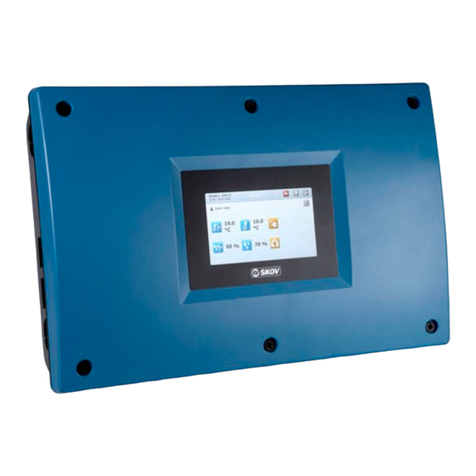
DOL 534 • DOL 539
5 Circuit diagrams ...........................................................................................................................................34
5.1 General information about circuit diagrams ......................................................................... 34
5.1.1 Color code.................................................................................................................................. 34
5.1.2 Power supply isolator................................................................................................................. 34
5.1.3 Letter Code ................................................................................................................................ 34
5.1.4 Example of connection............................................................................................................... 35
5.1.5 Connection of DC supplied coil.................................................................................................. 36
5.1.6 Overview of connection terminals .............................................................................................. 37
5.1.6.1 Power supply (-K1.1) ................................................................................................................. 37
5.1.6.2 Main module (-K1.2) .................................................................................................................. 37
5.1.6.3 I/O module (-K1.3) ..................................................................................................................... 37
5.1.6.4 Triac module (-K1.4) .................................................................................................................. 37
5.1.6.5 Loop modules (-K1.5) and (-K1.6) ............................................................................................. 37
5.2 Supply voltage for I/O module /main module........................................................................ 38
5.3 Alarm......................................................................................................................................... 38
5.4 Emergency opening................................................................................................................. 39
5.4.1 ON/OFF - medium and large ..................................................................................................... 39
5.4.2 ON/OFF - medium and large - parallel....................................................................................... 39
5.4.3 Temperature controlled - medium and large.............................................................................. 40
5.4.4 Emergency opening with Mini-UPS ........................................................................................... 40
5.5 Air circulator............................................................................................................................. 41
5.5.1 One-phase / Three-phase.......................................................................................................... 41
5.5.2 0-10V analog.............................................................................................................................. 41
5.5.3 Chill Unit..................................................................................................................................... 42
5.6 Wall fan ..................................................................................................................................... 42
5.6.1 BF 50 LPC ON/OFF .................................................................................................................. 42
5.6.2 BF 50 LPC VAR ........................................................................................................................ 43
5.6.3 BF 50 ON/OFF EL .................................................................................................................... 43
5.6.4 BF 50 ON/OFF AIR ................................................................................................................... 44
5.6.5 DA 1700 LPC 1x230 V .............................................................................................................. 44
5.6.6 DA 1700 LPC 3x400 V or 3x230 V ............................................................................................ 45
5.6.7 DA 1700 3x400 V or 3x230 V .................................................................................................... 45
5.7 Fan speed controller................................................................................................................ 46
5.7.1 Internal fan speed controller, two parallel fans .......................................................................... 46
5.7.2 DOL 31 fan speed controller ...................................................................................................... 46
5.7.3 Frequency converter .................................................................................................................. 47
5.7.4 Frequency converter DA 74CV stepless / Dynamic MultiStep................................................... 47
5.7.5 LPC motor controller .................................................................................................................. 48
5.7.6 LPC / DA 74CO ON/OFF / Dynamic MultiStep .......................................................................... 48
5.7.7 LPC / DA 74CV stepless / Dynamic MultiStep........................................................................... 49
5.8 Winch motors, all positions .................................................................................................... 50
5.8.1 DA 74CO ON/OFF ..................................................................................................................... 50
5.8.2 DA 74CV / BC stepless.............................................................................................................. 50
5.8.3 DA 75A ON/OFF 24 V................................................................................................................ 51
5.8.4 DA 75A stepless 24 V ................................................................................................................ 51
5.8.5 DA 75A stepless 230 V without potentiometer........................................................................... 52
5.8.6 DA 75A stepless 230 V .............................................................................................................. 52
5.8.7 Connection of two or several DA 75A 230 V.............................................................................. 53
5.8.8 DA 174 stepless 24 V ................................................................................................................ 54
5.8.9 DA 175 ON/OFF 24 V ................................................................................................................ 54
5.8.10 DA 175 stepless 24 V ................................................................................................................ 55
5.8.11 DA 175 ON/OFF 230 V .............................................................................................................. 55
5.8.12 DA 175 230 V stepless .............................................................................................................. 56
5.9 MultiStep, FreeRange (houses with pop holes) .................................................................... 57
5.9.1 Air outlet DA 74CO ON/OFF fan / stop relay ............................................................................. 57
5.9.2 Air outlet with several fans / stop relays..................................................................................... 58
5.9.3 Pop holes detection ................................................................................................................... 59
5.10 Door opening............................................................................................................................ 59
Circuit Diagrams and Cable Plans


