Page 4
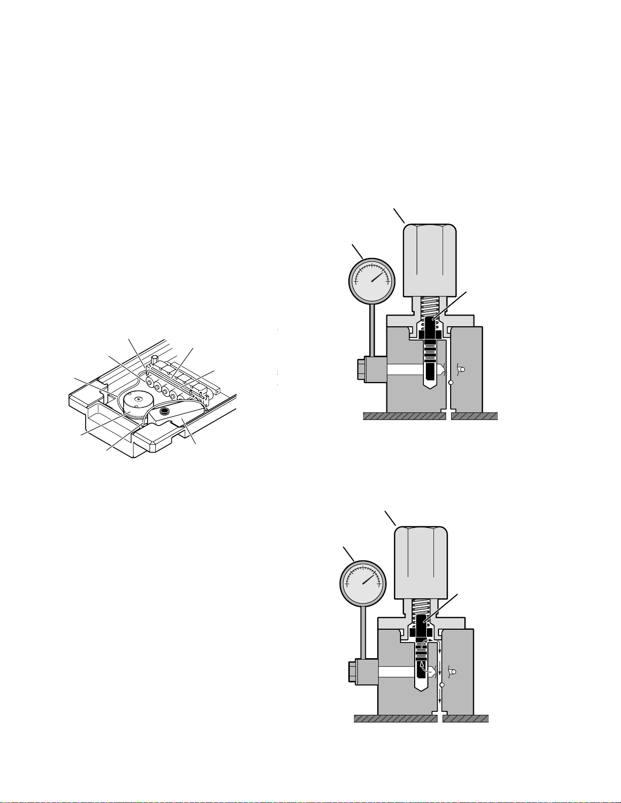
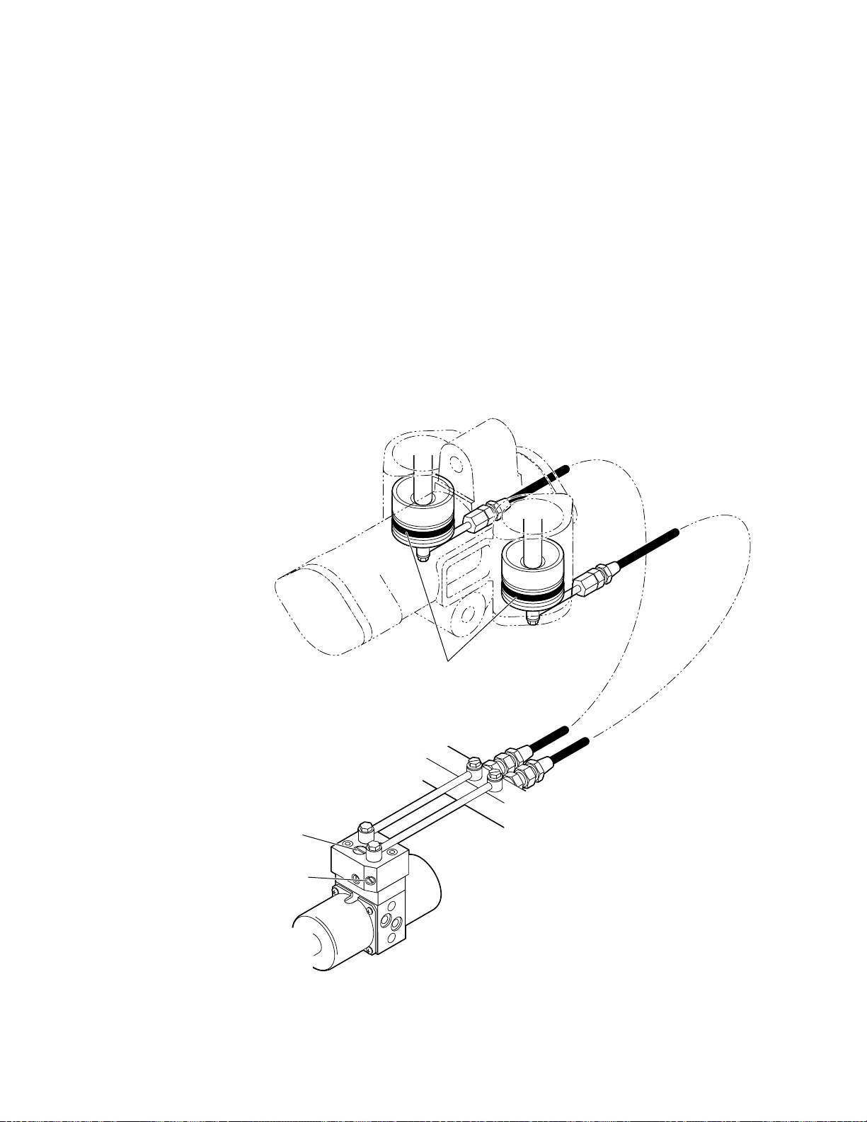
e. Mini-Valve Right Port Activated
(See figure 1-6)
Slave Cylinder Piston Moves to Left
Right Mini-Valve Port is Supply Line
Left Mini-Valve Port is Return Line
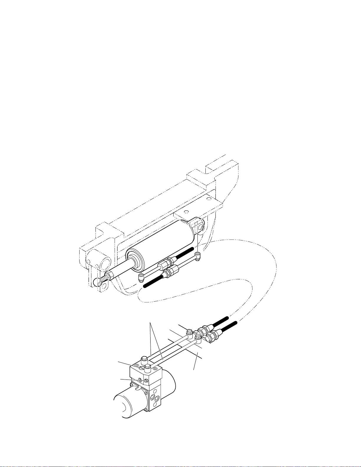
f. Mini-Valve Left Port Activated
(See figure 1-7.)
Slave Cylinder Piston Moves to Right
Left Mini-Valve Port is Supply Line
Right Mini-Valve Port is Return Line
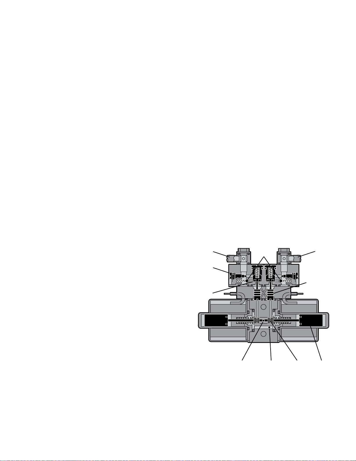
1. Spool Valve - Pushed to the left by electric
solenoid. This opens the internal oil pressure gal-
ley allowing the fluid to go through the check valve
andontothecylinder. Also, thespoolvalveopens
the oil return line providing an oil path through the
internal oil galley back to the reservoir.
2. PilotPlunger Valve- Leftpilotplungervalve
ispushedupbytheincomingoilpressuremechani-
callyopeningthecheckvalvelocatedaboveitinthe
returncircuit. Thisactionallowstheoilfromtheleft
side of the slave cylinder to go back into the
reservoir. The right pilot plunger valve is not
affected in this operation mode.
3. Check Valves - Both check valves are
opened in this operation mode. The right check
valveispushedopenbytheoilpressurecreatedby
thepump. Theoilthencontinuestogothrough the
lines and pushes the slave cylinder piston to the
left. At the same time, the left check valve is held
open mechanically by the pilot plunger providing a
returnpathfortheoilthroughthemini-valveback
to the reservoir.
4. SpeedAdjustment-Therightspeed control
(output side) does not have any effect in this
operation mode because the oil is routed around
thespeedadjustment throughaby-passvalve and
then to the output port. The left speed adjustment
controls the speed of the table function by restrict-
ing the amount of oil going back into the reservoir.
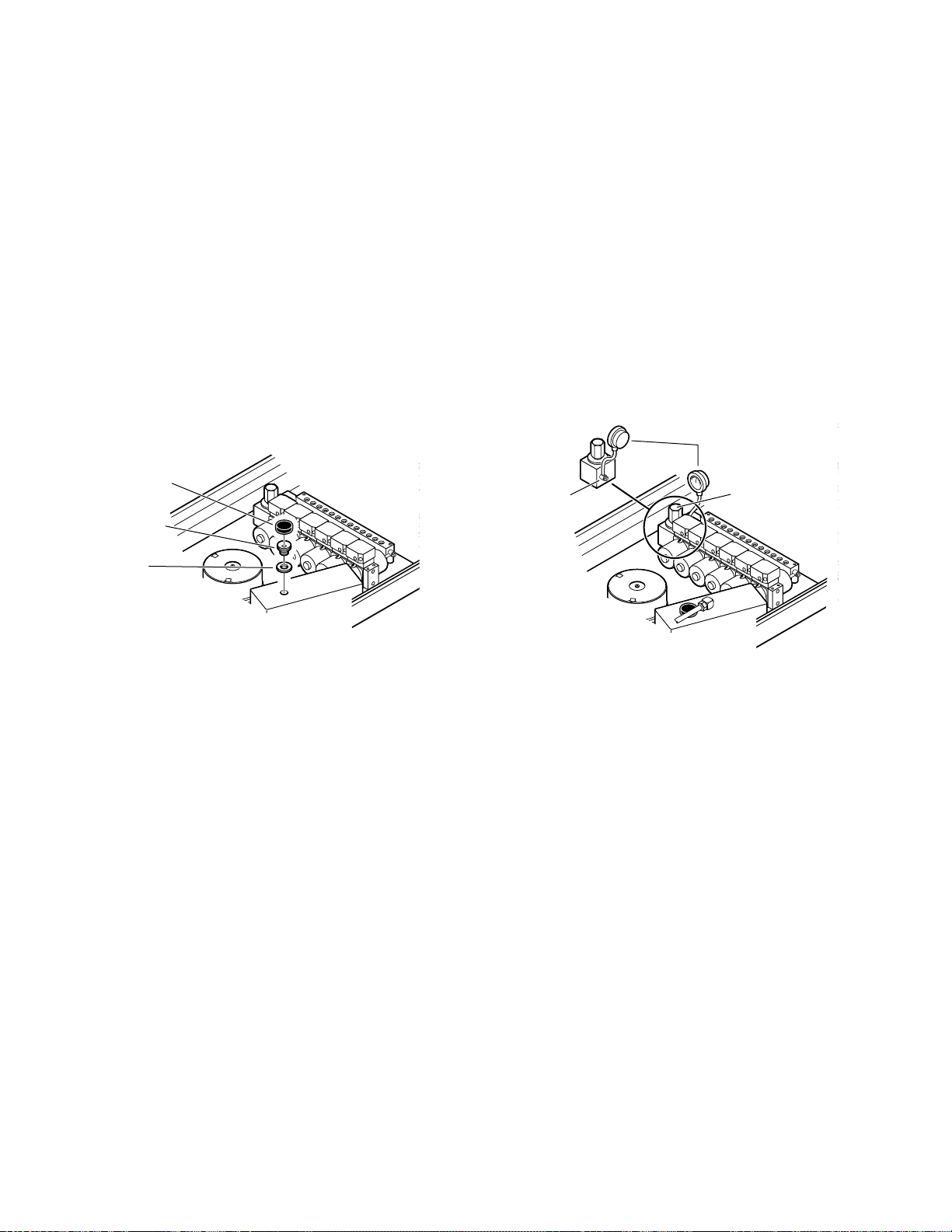
1. Spool Valve -Pushed to the right by electric
solenoid.Thisopenstheinternaloilpressuregalley
allowingthefluidtogothroughthecheckvalveand
onto thecylinder. Also, thespool valveopensthe
oil return line providing an oil path through the
internal oil galley back to the reservoir.
2. PilotPlunger Valve-Right pilotplungervalve
ispushedupbytheincomingoilpressuremechani-
callyopeningthecheckvalvelocatedaboveitinthe
return circuit. This action allows the oil from the
right side of the slave cylinder to go back into the
reservoir. Theleftpilotplungervalveisnotaffected
in this operation mode.
3. CheckValves-Bothcheckvalvesareopened
in this operation mode. The left valve is pushed
openbytheoilpressurecreatedbythepump. The
oil then continues to go through the lines and
pushestheslavecylinderpistontotheright. Atthe
same time, the right check valve is held open
mechanicallybythepilotplungerprovidingareturn
pathfortheoil throughthemini-valve backtothe
reservoir.
4. Speed Adjustment - The left speed control
(output side) does not have any effect in this oper-
ation mode because the oil is routed around the
speed adjustment through a by-pass valve and
thentotheoutputport. Therightspeedadjustment
controls the speed of the table function by restrict-
ing the amount of oil going back to the reservoir.
Figure 1-6. Mini-Valve Right Port Activated Figure 1-7. Mini-Valve Left Port Activated
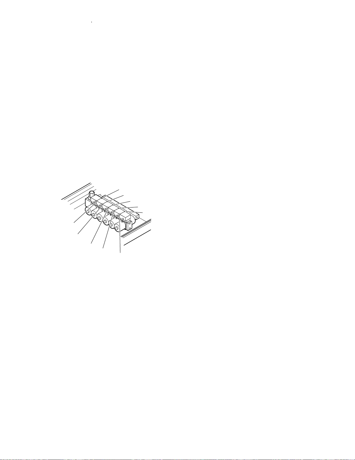
INLET OUTLET
INLET
OUTLET