manuals.online logo
Brands
  1. Home
  2. •
  3. Brands
  4. •
  5. Smartwares
  6. •
  7. Switch
  8. •
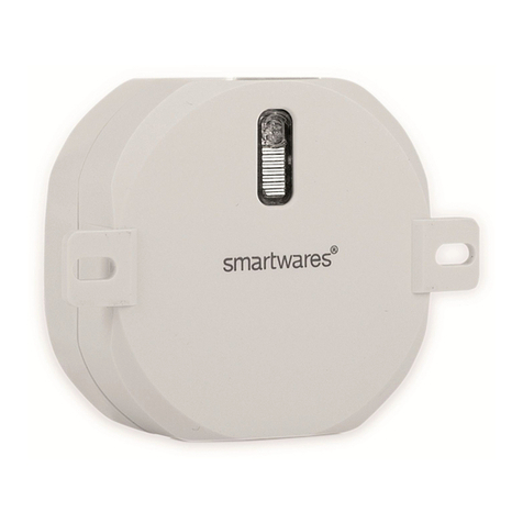
  9. Smartwares SH4-90259 User manual

Smartwares SH4-90259 User manual

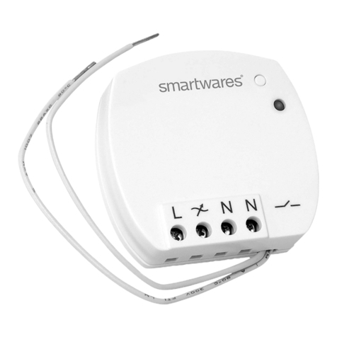
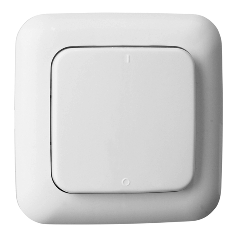
EN Wirelessbuilt-inup/downswitch
NL Draadloze omhoog/omlaag inbouwschakelaar
DE Eingebauter Funk-Aufwärts/Abwärtsschalter
FR Commutateur haut/bas sans fil intégré
ES Interruptor ascenso/descenso integrado inálmbrico
IT Interrittore salita/discesa integrato senza fili
PL
Bezprzewodowy przełącznik w górę/w dół
SH4-90259
EN Instruction manual
PREPARATION BEFORE USE
Please read the operating instructions!
Observe the warning and safety notes!
In your electrical circuit panel, locate the circuit breaker control for the
wall switch you will be working on. Switch the circuit off.
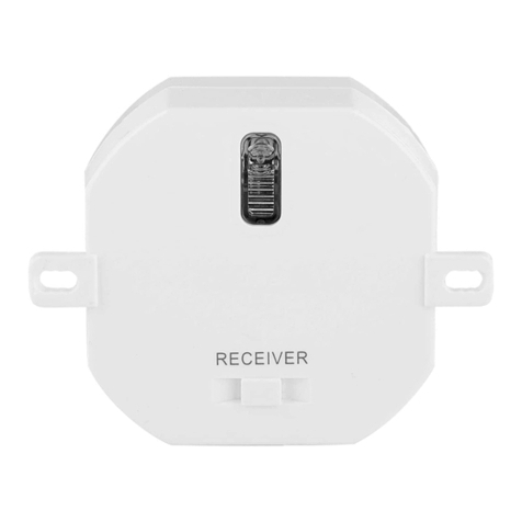
CONNECTING THE RECEIVER TO THE POWER SUPPLY (1)
Connect the phase wire (brown) to L and connect the neutral wire
(blue) to N.
Connecting the receiver to the roll-down shutter motor (standard
connection) (2)
First consult the instruction manual of the motor before connecting it.
A. Connect the “UP/OPEN” pin of the motor to B and connect the
“DOWN/CLOSE” pin of the motor to A.
ðNOTE: For the correct connections of a potential free contact,
please consult the instruction manual of the gate or garage door
motor.
B. Connect the phase wire of the motor (black) with C.
MOUNTING THE RECEIVER
Mount the receiver in place of the existing up/down switch and switch
on the power with the power switch in your electric circuit panel.
PAIRING
Pairing the receiver with a sender
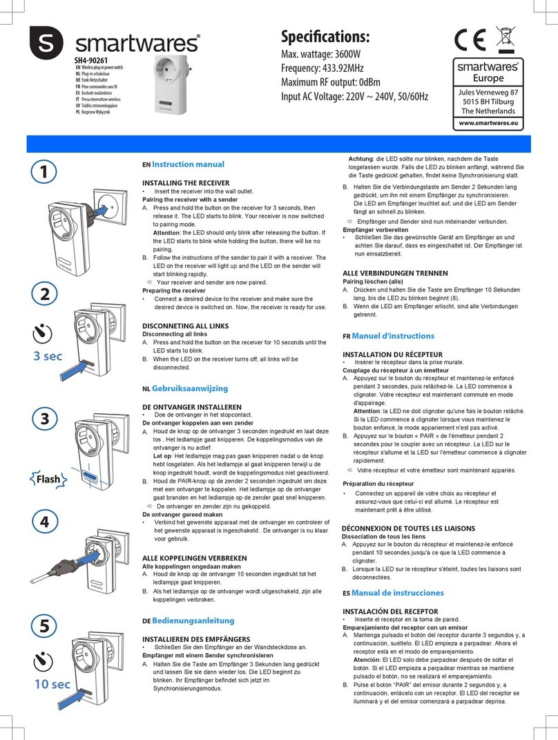
A. Press and hold the button on the receiver for 3 seconds, then
release it (5). The LED starts to blink. Your receiver is now
switched to pairing mode.
Attention: the LED should only blink after releasing the button. If
the LED starts to blink while holding the button, there will be no
pairing.
B. Press the “PAIR” button on the sender for 2 seconds to pair it with
a receiver. The LED on the receiver will light up and the LED on
the sender will start blinking rapidly.
ðYour receiver and sender are now paired.
Attention: it is possible to pair a receiver with multiple senders, eight
memory positions are available.
SETTING A TIMER ON THE RECEIVER
A. Short press the button on the receiver one time, then press and
hold the button on the receiver for 3 seconds and release it.
B. There are 4 modes: A, B, C, D. The factory setting is mode A.
C. Press the “I/ON” button on the sender to go to the next mode:
B>C>D. Press the “O/OFF” button on the sender to go to the
previous mode: D>C>B>A.
D. To fix the mode you need, press the learning button for 3
seconds. The LED will turn on continuously to confirm the set
mode.
Mode The receiver turns
off
LED blinks Use
A Manual up/down 1x Shutters
B Close/down after 1
sec
2x Electric garage
door / gate
C Close/down after 5
sec
3x Door opener
D Close/down after 120
sec
4x Lighting
NOTE: the program mode lasts for 10 seconds; if the receiver does
not receive a signal of a sender within these 10 seconds, the program
mode will stop.
OPERATING RECEIVERS
• Press the “I/ON” button on the sender to activate the receiver.
• Press the “O/OFF” button on the sender to turn off the receiver.
Disconnecting all links
A. When the switch is connected to the power supply, press and
hold the button on the built-in switch for 6 seconds, then release
it.
B. The LED starts to blink quickly for 12 seconds.
C. During this period, press the button again, the LED will start to
blink slowly, then stops blinking and is constantly lit.
D. All links will be disconnected.
NL Gebruiksaanwijzing
VOORBEREIDING VOOR GEBRUIK
Lees de gebruiksinstructies aandachtig door.
Neem de waarschuwing en veiligheidsvoorschriften in acht.
Zoek in uw stoppenkast de stroomonderbreker voor de
wandschakelaar waaraan u gaat werken.
Schakel de stroom uit.
DE ONTVANGER AANSLUITEN OP DE VOEDING
Sluit de fasedraad (bruin) aan op L en sluit de neutrale draad (blauw)
aan op N.
De ontvanger aansluiten op de rolluikmotor
(standaardaansluiting)
Raadpleeg de gebruiksaanwijzing van de motor voordat u deze
aansluit.
A. Sluit de UP/OPEN-pin (OMHOOG/OPENEN) van de motor aan
op B en sluit de DOWN/CLOSE-pin (OMLAAG/SLUITEN) van de
motor aan op A.
ðOPMERKING: Voor de juiste aansluiting van een potentiaalvrij
contact raadpleegt u de gebruiksaanwijzing van de motor voor de
poort of garagedeur.
B. Sluit de fasedraad van de motor (zwart) aan op C.
DE ONTVANGER MONTEREN
Monteer de ontvanger in plaats van de bestaande omhoog/omlaag-
schakelaar en schakel de stroom in met de aan/uit-schakelaar in de
stoppenkast.
KOPPELEN
De ontvanger koppelen aan een zender
A. Houd de knop op de ontvanger 3seconden ingedrukt en laat
deze los (5). Het ledlampje gaat knipperen. De koppelingsmodus
van de ontvanger is nu actief.
Let op: Het ledlampje mag pas gaan knipperen nadat u de knop
hebt losgelaten. Als het ledlampje al gaat knipperen terwijl u de
knop ingedrukt houdt, wordt de koppelingsmodus niet
geactiveerd.
B. Houd de PAIR-knop op de zender 2seconden ingedrukt om deze
met een ontvanger te koppelen. Het ledlampje op de ontvanger
gaat branden en het ledlampje op de zender gaat snel knipperen.
ðDe ontvanger en zender zijn nu gekoppeld.
Let op: Het is mogelijk een ontvanger te koppelen aan meerdere
zenders. Er zijn acht geheugenposities beschikbaar.
EEN TIMER INSTELLEN OP DE ONTVANGER
A. Druk één keer kort op de knop van de ontvanger, houd de knop
van de ontvanger vervolgens 3seconden ingedrukt en laat deze
los.
B. Er zijn 4 modi beschikbaar: A, B, C en D. De fabrieksinstelling is
modus A.
220-240 VAC
50/60Hz
Motor
Flash
10 sec
3 sec
1
2
3
4
5
Speci cations:
AC input Voltage:230V, 50Hz
Maximum range: 50 m
Maximum power: 300 W
Operating temperature: 0 - 35°C
Maximum RF output: 0dBm
Built-in switch: 433.92 Mhz
C. Druk op de knop I/ON (I/AAN) van de zender om
naar de volgende modus te gaan: B > C >D. Druk op
de knop O/OFF (O/UIT) van de zender om naar de
vorige modus te gaan: D > C > B > A.
D. Als u de gewenste modus wilt vastzetten, houdt u de
leerknop 3seconden ingedrukt. De led blijft continu
branden om de ingestelde modus te bevestigen.
Modus De ontvanger
wordt
uitgeschakeld
De led
knippert
Gebruik
A Handmatig
omhoog/omlaag
1x Rolluik
B Sluiten/omlaag na
1seconde
2x Elektrische
garagedeur/
poort
C Sluiten/omlaag na
5seconden
3x Deuropener
D Sluiten/omlaag na
120seconden
4x Verlichting
OPMERKING: De programmeermodus blijft 10seconden
actief. Als de ontvanger binnen deze 10seconden geen
signaal ontvangt, wordt de programmeermodus gestopt.
DE ONTVANGERS BEDIENEN
• Druk op de knop I/ON (I/AAN) van de zender om de
ontvanger te activeren.
• Druk op de knop O/OFF (I/UIT) van de zender om
de ontvanger uit te schakelen.
Disconnecting all links
A. Wanneer het apparaat op de voeding is aangesloten,
houdt u de knop op de ingebouwde schakelaar
6seconden ingedrukt. Vervolgens laat u deze los.
B. Het ledlampje knippert 12seconden in een snel
tempo.
C. Als u gedurende deze periode nogmaals op de knop
drukt, gaat het ledlampje langzaam knipperen.
Daarna stop het knipperen en blijft het lampje
branden.
D. Alle koppelingen worden verbroken.
DE Bedienungsanleitung
VORBEREITUNG
Lesen Sie bitte die Bedienungshinweise!
Befolgen Sie die Warn- und Sicherheitshinweise!
Suchen Sie in Ihrem Sicherungskasten den
Trennschalter für den Stromkreis des Wandschalters,
den Sie auswechseln wollen.
Schalten Sie den Stromkreis ab.
EMPFÄNGER AN DER STROMVERSORGUNG
ANSCHLIESSEN
Verbinden Sie den Phasenleiter (braun) mit L und den
Neutralleiter (blau) mit N.
Empfänger am Rollladenmotor anschließen
(Standardanschluss)
Lesen Sie vor dem Anschließen zunächst die
Bedienungsanleitung für den Motor.
A. Verbinden Sie den Stift „UP/OPEN“ (Auf/Öffnen) des
Motors mit B und den Stift „DOWN/CLOSE“ (Ab/
Schließen) des Motors mit A.
ðHINWEIS: Wegen der korrekten Anschlüsse eines
potentialfreien Kontakts halten Sie sich bitte an die
Bedienungsanleitung des Tor- oder
Garagentürmotors.
B. Verbinden Sie den Phasenleiter des Motors
(schwarz) mit C.
EMPFÄNGER MONTIEREN
Installieren Sie den Empfänger abstelle des
vorhandenen Auf/Ab-Schalters und schalten Sie den
Strom in Ihrem Sicherungskasten ein.
SYNCHRONISIEREN
Empfänger mit einem Sender verbinden
A. Halten Sie die Taste am Empfänger 3Sekunden
lang gedrückt und lassen Sie sie dann wieder los (5).
Die LED beginnt zu blinken. Ihr Empfänger befindet
sich jetzt im Synchronisierungsmodus.
Achtung: die LED sollte nur blinken, nachdem die
Taste losgelassen wurde. Falls die LED zu blinken
anfängt, während Sie die Taste gedrückt gehalten,
findet keine Synchronisierung statt.
B. Halten Sie die Verbindungstaste am Sender
2Sekunden lang gedrückt, um ihn mit einem
Empfänger zu synchronisieren. Die LED am
Empfänger leuchtet auf, und die LED am Sender
fängt an schnell zu blinken.
ðEmpfänger und Sender sind nun miteinander
verbunden.
Achtung: Ein Empfänger kann mit mehreren Sendern
gekoppelt werden. Es stehen acht Speicherpositionen
zur Verfügung.
ZEITSCHALTUNG AM EMPFÄNGER
KONFIGURIEREN
A. Drücken Sie einmal kurz die Taste am Empfänger.
Halten Sie dann die Taste am Empfänger
3Sekunden lang gedrückt und lassen Sie sie dann
wieder los.
B. Es gibt 4 Betriebsarten: A, B, C und D.
Standardvorgabe ist Betriebsart A.
C. Drücken Sie die Taste „I/ON“ am Sender, um zur
nächsten Betriebsart zu wechseln. B>C>D. Drücken
Sie die Taste „O/OFF“ am Sender, um zur
vorhergehenden Betriebsart zu wechseln: D>C>B>A.
D. Um den gewünschten Modus einzustellen, halten Sie
die Lerntaste 3Sekunden lang gedrückt. Die LED
leuchtet durchgehend als Hinweis darauf, dass der
Modus eingestellt ist.
Betrieb
sart
Der Empfänger
schaltet sich aus
LED blinkt Bedienung
A Manuell auf/ab 1x Rollläden
B Schließen/Ab
nach 1Sek.
2x Elektrische(s
)
Garagentor/-
tür
C Schließen/Ab
nach 5Sek.
3x Türöffner
D Schließen/Ab
nach 120Sek.
4x Beleuchtung
HINWEIS: Der Programmiermodus dauert 10Sekunden;
falls der Empfänger innerhalb dieser 10Sekunden kein
Signal vom Sender erhält, wird der Programmiermodus
gestoppt.
EMPFÄNGERBETRIEB
• Drücken Sie die Taste „I/ON“ (I/Ein) am Sender, um
den Empfänger zu aktivieren.
• Drücken Sie die Taste „O/OFF“ (0/Aus) am Sender,
um den Empfänger auszuschalten.
Pairing löschen (alle)
A. Wenn der Einbauschalter an der Stromversorgung
angeschlossen ist, drücken und halten Sie die Taste
am Schalter 6Sekunden lang und lassen Sie sie
dann wieder los.
B. Die LED beginnt 12Sekunden lang zu blinken.
C. Drücken Sie die Taste währenddessen erneut. Die
LED blinkt zunächst langsam und leuchtet dann
dauerhaft.
D. Alle Verbindungen sind getrennt.
FR Manuel d'instructions
PRÉPARATION AVANT UTILISATION.
Veuillez lire attentivement le mode d'emploi.
Respectez les avertissements et les remarques
concernant la sécurité.
Dans votre panneau de circuit électrique, localisez la
commande du disjoncteur pour l'interrupteur mural sur
lequel vous allez travailler.
Coupez le circuit.
RACCORDEMENT DU RÉCEPTEUR À
L'ALIMENTATION ÉLECTRIQUE
Branchez le fil de phase (marron) sur L et le fil neutre
(bleu) sur N.
Raccordement du récepteur au moteur du volet
roulant (raccordement standard)
Consultez d'abord le mode d'emploi du moteur avant de
le connecter.
A. Connectez la broche «UP/OPEN» du moteur à B et
connectez la broche «DOWN/CLOSE» du moteur à
A.
ðREMARQUE: Pour le raccordement correct d'un
contact libre de potentiel, veuillez consulter le mode
d'emploi du moteur de portail ou de porte de garage.
B. Raccordez le fil de phase du moteur (noir) à C.
MONTAGE DU RÉCEPTEUR
Installez le récepteur à la place de l'interrupteur haut/bas
existant et mettez l'appareil sous tension à l'aide de
l'interrupteur d'alimentation de votre panneau de circuit
électrique.
APPARIEMENT
Couplage du récepteur à un émetteur
A. Appuyez sur le bouton du récepteur et maintenez-le
enfoncé pendant 3 secondes, puis relâchez-le (5).
La LED commence à clignoter. Votre récepteur est
maintenant commuté en mode d'appairage.
Attention: la LED ne doit clignoter qu'une fois le
bouton relâché. Si la LED commence à clignoter
lorsque vous maintenez le bouton enfoncé, le mode
appariement n'est pas activé.
B. Appuyez sur le bouton «PAIR» de l'émetteur
pendant 2 secondes pour le coupler avec un
récepteur. La LED sur le récepteur s'allume et la
LED sur l'émetteur commence à clignoter
rapidement.
ðVotre récepteur et votre émetteur sont maintenant
appariés.
Attention: il est possible de coupler un récepteur avec
plusieurs émetteurs, huit positions de mémoire sont
disponibles.
RÉGLAGE D'UNE MINUTERIE SUR LE
RÉCEPTEUR
A. Appuyez brièvement une fois sur le bouton du
récepteur, maintenez-le enfoncé pendant 3
secondes, puis relâchez-le.
B. Il y a 4modes: A, B, C et D. La configuration d'usine
est le mode A.
C. Appuyez sur le bouton «I/ON» de l'émetteur pour
passer au mode suivant: B>C>D. Appuyez sur le
bouton «O/OFF» de l'émetteur pour revenir au
mode précédent: D>C>B>A.
D. Pour fixer le mode dont vous avez besoin, appuyez
sur la touche d'apprentissage pendant 3 secondes.
La LED s'allume en permanence pour confirmer le
mode réglé.
Mode Le récepteur
s'éteint
La LED
clignote
Utilisation
A Montée/descente
manuelle
1x Volets
B Fermeture/
descente après 1
s
2x Porte de
garage /
portail
électrique
C Fermeture/
descente après 5
s
3x Ouvre-porte
D Fermeture/
descente après
120 s
4x Éclairage
Attention: le mode programme dure 10 secondes; si le
récepteur ne reçoit pas de signal d'un émetteur dans ces
10 secondes, le mode programme s'arrête.
EN Wirelessbuilt-inup/downswitch
NL Draadloze omhoog/omlaag inbouwschakelaar
DE Eingebauter Funk-Aufwärts/Abwärtsschalter
FR Commutateur haut/bas sans fil intégré
ES Interruptor ascenso/descenso integrado inálmbrico
IT Interrittore salita/discesa integrato senza fili
PL
Bezprzewodowy przełącznik w górę/w dół
SH4-90259
RÉCEPTEURS DE COMMANDE
• Appuyez sur le bouton «I/ON» de l'émetteur pour activer le
récepteur.
• Appuyez sur le bouton «O/OFF» de l'émetteur pour désactiver
le récepteur.
Déconnecter tous les liens
A. Lorsque l'interrupteur intégré est connecté à l'alimentation
électrique, appuyez sur le bouton de l'interrupteur, maintenez-le
enfoncé pendant 6secondes, puis relâchez.
B. La LED commence à clignoter rapidement pendant 12secondes.
C. Pendant ce délai, appuyez de nouveau sur le bouton. La LED
commence à clignoter lentement, puis s'arrête de clignoter et
reste allumée.
D. Toutes les liaisons sont alors déconnectées.
ES Manual de instrucciones
PREPARACIÓN ANTES DEL USO
Lea las instrucciones de funcionamiento.
Respete las advertencias y notas de seguridad.
En el panel del circuito eléctrico, busque el control del disyuntor del
interruptor de pared en el que realizará la operación.
Apague el circuito.
CONEXIÓN DEL RECEPTOR A LA FUENTE DE
ALIMENTACIÓN
Conecte el cable de fase (marrón) a L y conecte el cable neutro
(azul) a N.
Conexión del receptor con el motor de la persiana enrollable
(conexión estándar)
En primer lugar, consulte el manual de instrucciones del motor antes
de conectarlo.
A. Conecte la clavija de “ARRIBA/ABRIR” del motor con B y la
clavija de “BAJADA/CERRAR” con A.
ðNOTA: Para saber cuáles son las conexiones correctas de un
contacto sin potencial, consulte el manual de instrucciones de la
verja o el motor de la puerta del garaje.
B. Conecte el cable de fase del motor (negro) a C.
MONTAJE DEL RECEPTOR
Monte el receptor en lugar del interruptor de subida/bajada existente
y encienda el interruptor de encendido del panel del circuito eléctrico.
EMPAREJAMIENTO
Emparejamiento del receptor con un emisor
A. Mantenga pulsado el botón del receptor durante 3 segundos y, a
continuación, suéltelo (5). El LED empieza a parpadear. Ahora el
receptor está en el modo de emparejamiento.
Atención: El LED solo debe parpadear después de soltar el
botón. Si el LED empieza a parpadear mientras se mantiene
pulsado el botón, no se realizará el emparejamiento.
B. Pulse el botón “PAIR” del emisor durante 2 segundos y, a
continuación, emparéjelo con un receptor. El LED del receptor se
iluminará y el del emisor comenzará a parpadear deprisa.
ðEl receptor y el emisor estarán ahora emparejados.
Atención: Es posible vincular un receptor con múltiples emisores;
hay ocho posiciones de memoria disponibles.
CONFIGURACIÓN DE UN TEMPORIZADOR EN EL
RECEPTOR
A. Pulse brevemente el botón del receptor una vez y, a
continuación, manténgalo pulsado durante 3 segundos y suéltelo.
B. Hay 4 modos: A, B, C y D. El ajuste de fábrica es el modo A.
C. Pulse el botón “I/ON” del emisor para pasar al siguiente modo:
B>C>D. Pulse el botón “O/OFF” del emisor para ir al modo
anterior: D>C>B>A.
D. Para fijar el modo que necesita, pulse el botón de aprendizaje
durante 3 segundos. El LED permanecerá encendido para
confirmar el modo establecido.
Modo El receptor se apaga El LED
parpadea
Uso
A Subir/bajar
manualmente
1 vez Persianas
B Cerrar/bajar tras 1
segundo
2 veces Verja/puerta de
garaje eléctrica
C Cerrar/bajar tras 5
segundos
3 veces Abrepuertas
D Cerrar/bajar tras 120
segundos
4 veces Iluminación
NOTA: El modo de programa dura 10 segundos; si el receptor no
recibe señal de un emisor durante estos 10 segundos, el modo del
programa se detendrá.
FUNCIONAMIENTO DE LOS RECEPTORES
• Pulse el botón “I/ON” del emisor para activar el receptor.
• Pulse el botón “O/OFF” del emisor para apagar el receptor.
Desconectar todas las conexiones.
A. Con el interruptor conectado al suministro de alimentación,
mantenga pulsado el botón del receptor incorporado durante 6
segundos y, a continuación, suéltelo.
B. El LED empieza a parpadear rápido durante 12 segundos.
C. Durante este tiempo, vuelva a pulsar el botón. El LED comenzará
a parpadear lentamente, dejará de parpadear y permanecerá
iluminado.
D. Todas las conexiones se interrumpirán.
IT Istruzioni per l'uso
PREPARAZIONE PER L’USO
Leggere le istruzioni per l'uso!
Osservare le avvertenze e le istruzioni di sicurezza!
Nel quadro elettrico, individuare l'interruttore automatico relativo
l'interruttore a muro su cui si sta lavorando.
Interrompere il circuito elettrico.
COLLEGAMENTO DEL RICEVITORE ALL'ALIMENTAZIONE
Collegare il filo di fase (marrone) a L e collegare il filo neutro (blu) a
N.
Collegamento del ricevitore al motore dell'oscurante avvolgibile
(collegamento standard)
Prima di collegare, consultare il manuale di istruzioni.
A. Collegare il pin "SU/APRI" del motore a B e collegare il pin "GIÙ/
CHIUDI" del motore ad A.
ðNOTA: Per il corretto collegamento di un contatto a potenziale zero,
consultare il manuale di istruzioni del motore cancello o della porta
del garage.
B. Collegare il filo di fase del motore (nero) con C.
MONTAGGIO DEL RICEVITORE
Montare il ricevitore al posto del frutto esistente e fornire
l'alimentazione tramite l’interruttore principale del quadro elettrico.
ASSOCIAZIONE
Associare il ricevitore ad un trasmettitore
220-240 VAC
50/60Hz
Motor
Flash
10 sec
3 sec
1
2
3
4
5
Speci cations:
AC input Voltage:230V, 50Hz
Maximum range: 50 m
Maximum power: 300 W
Operating temperature: 0 - 35°C
Maximum RF output: 0dBm
Built-in switch: 433.92 Mhz
A. Tenere premuto il pulsante sul ricevitore per 3
secondi e rilasciarlo (5). Il LED inizia a lampeggiare.
Il ricevitore si trova ora in modalità di associazione.
Attenzione: il LED deve lampeggiare solo dopo aver
rilasciato il pulsante. Se il LED inizia a lampeggiare
mentre il pulsante è premuto, l’associazione non
verrà eseguita.
B. Tenere premuto il pulsante "PAIR" sul trasmettitore
per 2 secondi per associarlo al ricevitore. Il LED sul
ricevitore si accende e il LED sul trasmettitore inizia
a lampeggiare rapidamente.
ðL'associazione tra ricevitore e trasmettitore è
avvenuta correttamente.
Attenzione: è possibile associare un ricevitore a più
trasmettitori, utilizzando le otto sei posizioni di memoria
disponibili.
IMPOSTAZIONE DI UN TIMER SUL RICEVITORE
A. Premere brevemente una volta il pulsante sul
ricevitore, poi tenere premuto il pulsante sul
ricevitore per 3 secondi e rilasciarlo.
B. Sono disponibili 4 modalità: A, B, C, D.
L'impostazione di fabbrica è la modalità A.
C. Premere il pulsante “I/ON” sul trasmettitore per
selezionare le modalità in successione: B>C>D.
Premere il pulsante “O/OFF” sul trasmettitore per
passare alla modalità precedente: D>C>B>A.
D. Per impostare la modalità desiderata, premere il
pulsante di apprendimento per 3 secondi. Il LED si
accende fisso per confermare la modalità impostata.
Modalit
à
Il ricevitore si
spegne
Il LED
lampeggia
Uso
A Su/Giù manuale 1x Oscuranti
B Chiusura/
abbassamento
dopo 1 sec
2x Porta
elettrica del
garage /
cancello
C Chiusura/
abbassamento
dopo 5 sec
3x Apriporta
D Chiusura/
abbassamento
dopo 120 sec
4x Illuminazione
NOTA: la modalità programma rimane attiva per 10
secondi; se il ricevitore non riceve un segnale
proveniente da un trasmettitore entro 10 secondi, la
modalità programma si disattiva.
UTILIZZO DEI RICEVITORI
• Premere il tasto “I/ON” sul trasmettitore per attivare
il ricevitore.
• Premere il tasto “O/OFF” sul trasmettitore per
spegnere il ricevitore.
Disconnessione di tutti i collegamenti
A. Quando l'interruttore è collegato all'alimentazione,
tenere premuto il pulsante sull'interruttore da incasso
per 6 secondi e rilasciarlo.
B. Il LED inizia a lampeggiare rapidamente per 12
secondi.
C. Entro questo periodo, premere nuovamente il
pulsante, il LED inizia a lampeggiare lentamente, poi
smette di lampeggiare e rimane costantemente
acceso.
D. Tutte le associazioni sono state annullate.
PL Instrukcje użytkowania
PRZYGOTOWANIE PRZED UŻYCIEM
Przeczytaj instrukcję obsługi!
Przestrzegaj ostrzeżeń i informacji o bezpieczeństwie!
Na panelu elektrycznym znajdź bezpiecznik chroniący
obwód danego przełącznika ściennego.
Wyłącz obwód.
PODŁĄCZANIE ODBIORNIKA DO ŹRÓDŁA
ZASILANIA.
Podłącz przewód fazy (brązowy) do L, a neutralny
(niebieski) do N.
Podłączanie odbiornika do silnika elektrycznej rolety
(standardowe podłączenie)
Przed podłączeniem silnika zapoznaj się z jego
instrukcją obsługi.
A. Podłącz pin „UP/OPEN” (góra/otwórz) silnika do B, a
pin „DOWN/CLOSE” (dół/zamknij) silnika do A.
ðUWAGA: Opis prawidłowych podłączeń styku
bezpotencjałowego znajduje się w instrukcji obsługi
silnika bramy lub drzwi garażu.
B. Podłącz przewód fazy silnika (czarny) do C.
MOCOWANIE ODBIORNIKA
Zamontuj odbiornik zamiast istniejącego przełącznika
góra/dół i włącz zasilanie za pomocą przełącznika
zasilania na panelu elektrycznym.
PAROWANIE
Parowanie odbiornika z nadajnikiem
A. Naciśnij przycisk na odbiorniku iprzytrzymaj go
przez 3sekundy, następnie go puść (5). Kontrolka
LED zaczyna migać. Odbiornik jest teraz w trybie
parowania.
Uwaga: kontrolka LED powinna migać dopiero po
puszczeniu przycisku. Jeśli kontrolka LED zacznie
migać, gdy przycisk jest wciśnięty, parowanie nie
zadziała.
B. Naciśnij przycisk „PAIR” (parowanie) na nadajniku
iprzytrzymaj go przez 2sekundy, aby sparować
nadajnik z odbiornikiem. Włączy się kontrolka LED
na odbiorniku, a kontrolka LED na nadajniku zacznie
szybko migać.
ðOdbiornik i nadajnik są teraz sparowane.
Uwaga: odbiornik można sparować z wieloma
nadajnikami, dostępnych jest osiem pozycji pamięci.
USTAWIANIE REGULATORA CZASOWEGO W
ODBIORNIKU
A. Naciśnij krótko jeden raz przycisk na odbiorniku,
następnie naciśnij przycisk na odbiorniku
iprzytrzymaj go przez 3sekundy, po czym go puść.
B. Dostępne są 4 tryby: A, B, C, D. Fabrycznie jest
ustawiony tryb A.
C. Naciśnij przycisk „I/ON” (wł.) na nadajniku, aby
przejść do kolejnego trybu: B>C>D. Naciśnij przycisk
„O/OFF” (wył.) na nadajniku, aby przejść do
poprzedniego trybu: D>C>B>A.
D. Aby ustawić wybrany tryb, naciśnij przycisk uczenia i
przytrzymaj go przez 3 sekundy. Kontrolka LED
zapali się światłem stałym, aby potwierdzić
ustawiony tryb.
Tryb Odbiornik jest
wyłączony
LED miga Użytkowani
e
A Ręczne
podnoszenie/
opuszczanie
1x Rolety
B Zamykanie/
opuszczanie po 1
s
2x Elektryczne
drzwi
garażowe /
brama
C Zamykanie/
opuszczanie po 5
s
3x Napęd drzwi
D Zamykanie/
opuszczanie po
120 s
4x Oświetlenie
UWAGA: tryb programowania działa przez 10 sekund.
Jeśli w tym czasie odbiornik nie odbierze sygnału z
nadajnika, tryb programowania się wyłączy.
OBSŁUGA ODBIORNIKÓW
• Naciśnij przycisk „I/ON” (wł.) na nadajniku, aby
aktywować odbiornik.
• Naciśnij przycisk „O/OFF” (wył.) na nadajniku, aby
wyłączyć odbiornik.
Rozłączanie wszystkich połączeń
A. Gdy przełącznik jest podłączony do źródła zasilania,
naciśnij iprzytrzymaj przycisk na wbudowanym
przełączniku przez 6sekund, następnie go puść.
B. Kontrolka LED będzie przez 12 sekund szybko
migała.
C. W tym czasie naciśnij przycisk jeszcze raz. Kontrolka
LED zacznie migać powoli, następnie przestanie
migać i zapali się światłem stałym.
D. Wszystkie powiązania zostaną rozłączone.

This manual suits for next models

1

Other Smartwares Switch manuals

Smartwares SH4-90159 User manual

Smartwares

Smartwares SH4-90159 User manual

Smartwares SH4-90261 User manual

Smartwares

Smartwares SH4-90261 User manual

Smartwares SH5-RPD-02A User manual

Smartwares

Smartwares SH5-RPD-02A User manual

Smartwares SH4-99653 User manual

Smartwares

Smartwares SH4-99653 User manual

Smartwares 10.037.12 User manual

Smartwares

Smartwares 10.037.12 User manual

Smartwares SH4-99566FR User manual

Smartwares

Smartwares SH4-99566FR User manual

Smartwares 10.037.07 User manual

Smartwares

Smartwares 10.037.07 User manual

Smartwares SH5-SET-RD User manual

Smartwares

Smartwares SH5-SET-RD User manual

Smartwares SH5-TSW-C User manual

Smartwares

Smartwares SH5-TSW-C User manual

Smartwares SH4-99558 User manual

Smartwares

Smartwares SH4-99558 User manual

Smartwares 10.037.12 User manual

Smartwares

Smartwares 10.037.12 User manual

Smartwares SH4-90268 User manual

Smartwares

Smartwares SH4-90268 User manual

Smartwares SH4-99567 User manual

Smartwares

Smartwares SH4-99567 User manual

Smartwares SH4-90260 User manual

Smartwares

Smartwares SH4-90260 User manual

Smartwares SH4-99565AT User manual

Smartwares

Smartwares SH4-99565AT User manual

Smartwares SH4-90451 User manual

Smartwares

Smartwares SH4-90451 User manual

Smartwares SH4-90259 User manual

Smartwares

Smartwares SH4-90259 User manual

Smartwares SH4-99573 User manual

Smartwares

Smartwares SH4-99573 User manual

Smartwares SH4-99562 User manual

Smartwares

Smartwares SH4-99562 User manual

Smartwares SH5-RBS-10A User manual

Smartwares

Smartwares SH5-RBS-10A User manual

Smartwares SH4-99574FR User manual

Smartwares

Smartwares SH4-99574FR User manual

Smartwares SH5-RPS-36A User manual

Smartwares

Smartwares SH5-RPS-36A User manual

Smartwares SH8-90604 User manual

Smartwares

Smartwares SH8-90604 User manual

Smartwares SH5-RPS-23A/CH User manual

Smartwares

Smartwares SH5-RPS-23A/CH User manual

Popular Switch manuals by other brands

Black Box sW901aE manual

Black Box

Black Box sW901aE manual

MicroNet SP6510P8 Quick installation guide

MicroNet

MicroNet SP6510P8 Quick installation guide

GOPOD HD258B user manual

GOPOD

GOPOD HD258B user manual

ReadyLinks GL Series user guide

ReadyLinks

ReadyLinks GL Series user guide

Black Box SERVSWITCH KV3108SA-R4 Quick install guide

Black Box

Black Box SERVSWITCH KV3108SA-R4 Quick install guide

ITT neo-dyn 100p Installation and operation manual

ITT

ITT neo-dyn 100p Installation and operation manual

Belkin P75325 user manual

Belkin

Belkin P75325 user manual

Wiwav W1003-2FE1FX-I user manual

Wiwav

Wiwav W1003-2FE1FX-I user manual

ATEN VP2730 user manual

ATEN

ATEN VP2730 user manual

MST AXON user manual

MST

MST AXON user manual

Manhattan MES-08F instructions

Manhattan

Manhattan MES-08F instructions

AVMATRIX PVS0615 user manual

AVMATRIX

AVMATRIX PVS0615 user manual

Icron Icron WiRanger user guide

Icron

Icron Icron WiRanger user guide

ELRO HE877 quick start guide

ELRO

ELRO HE877 quick start guide

DANLERS CEPH NO Installation notes

DANLERS

DANLERS CEPH NO Installation notes

Moxa Technologies NPORT 6610 Quick installation guide

Moxa Technologies

Moxa Technologies NPORT 6610 Quick installation guide

PRO SIGNAL PSG3055 quick start guide

PRO SIGNAL

PRO SIGNAL PSG3055 quick start guide

HP HP E1368A/69A/70A user manual

HP

HP HP E1368A/69A/70A user manual

manuals.online logo
manuals.online logoBrands
  • About & Mission
  • Contact us
  • Privacy Policy
  • Terms and Conditions

Copyright 2025 Manuals.Online. All Rights Reserved.