manuals.online logo
Brands
  1. Home
  2. •
  3. Brands
  4. •
  5. SOMFY
  6. •
  7. Control Unit
  8. •
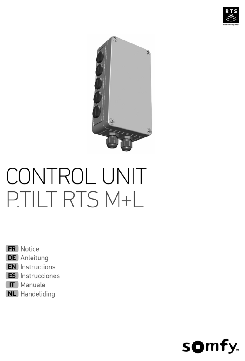
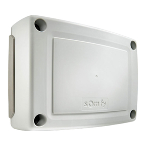
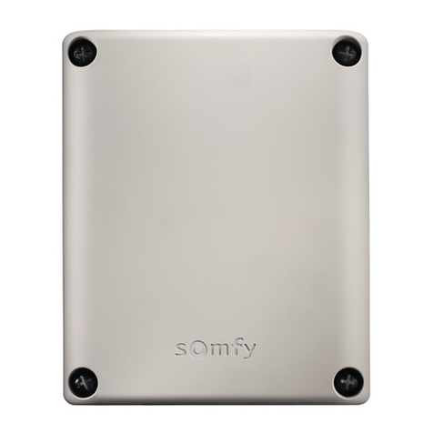
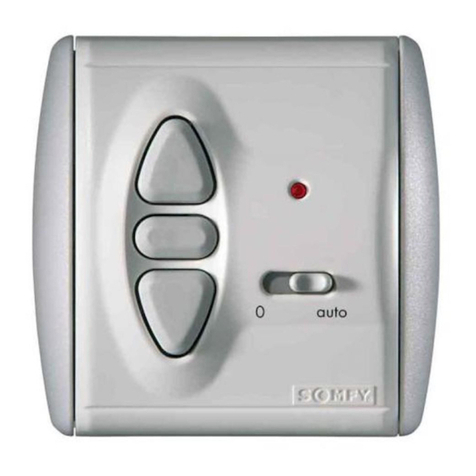
  9. SOMFY animeo KNX Master Control W8 User manual

SOMFY animeo KNX Master Control W8 User manual

www.somfy.com/DFS/manuals/
i
AUSTRIA
SOMFY GesmbH
www.somfy.at
Tel.: +43 (0) 662 625 308
AUSTRALIA
SOMFY Pty Limited
www.somfy.com.au
Tel.: +61 (0) 296 380 744
BELGIUM
SOMFY NV SA
www.somfy.be
Tel.: +32 (0) 27 120 770
BRASIL
SOMFY BRASIL Ltda
www.somfy.com.br
Tel.: +55 (0) 1 136 953 585
CANADA
SOMFY ULC
www.somfysystems.com
Tel.: +1 (0) 9 055 646 446
CHINA
SOMFY China Co Ltd.
www.somfy.com.cn
Tel.: +86 (0) 2 162 809 660
CYPRUS
SOMFY Middle East Co. Ltd.
www.somfy.com
Tel.: +357 (0) 25 345 540
CZECH REPUBLIC
SOMFY Spol s.r.o
www.somfy.cz
Tel.: +420 (0) 2 963 724 867
DENMARK
SOMFY Nordic AB
www.somfy.dk
Tel.: +45 (0) 65 325 793
FINLAND
SOMFY Nordic AB
www.somfy.fi
Tel.: +358 (0) 957 130 230
FRANCE
SOMFY France
www.somfy.fr
Tel.: +33 (0) 450 967 096
GERMANY
SOMFY GmbH
www.somfy.de
Tel.: +49 (0) 74 729 300
GREECE
SOMFY Hellas SA
www.somfy.com
Tel.: +30 (0) 2 106 146 768
HONG KONG
SOMFY Co. Ltd.
www.somfy.cn
Tel.: +852 (0) 25 236 339
HUNGARY
SOMFY Kft
www.somfy.hu
Tel.: +36 (0) 18 145 120
INDIA
SOMFY India Private Limited
www.somfy.co.in
Tel.: +91 (0) 1 146 111 555
ISRAEL
SISA HOME AUTOMATION LTD
www.somfy.co.il
Tel.: +972 (0) 39 525 554
ITALY
SOMFY Italia S.R.L
www.somfy.it
Tel.: +39 (0) 24 847 181
JAPAN
SOMFY K.K
www.somfy.co.jp
Tel.: +81 (0) 454 750 732
KOREA
SOMFY JOO
www.somfy.co.kr
Tel.: +82 (0) 316 005 250
KUWAIT
SOMFY Kuwait
www.somfy.com
Tel.: +965 (0) 9 889 467
LEBANON
SOMFY Lebanon
www.somfy.com.lb
Tel.: +961 (0) 1 427 888
MEXICO
SOMFY MEXICO SA de CD
www.somfy.mx
Tel.: +52 (0) 55 477 777 701
NETHERLANDS
SOMFY Nederland B.V
www.somfy.nl
Tel.: +31 (0) 235 544 900
NORWAY
SOMFY Nordic AB
www.somfy.no
Tel.: +47 (0) 41 576 639
POLAND
SOMFY SP Z.O.O
www.somfy.pl
Tel.: +48 (0) 225 095 300
PORTUGAL
SOMFY Portugal
www.somfy.pt
Tel.: +351 (0) 229 396 840
RUSSIA
SOMFY LLC
www.somfy.ru
Tel.: +7 (0) 953 604 186
SINGAPORE
SOMFY PTE LTD
www.somfy.com.sg
Tel.: +65 (0) 63 833 855
SPAIN
SOMFY Espana SA
www.somfy.es
Tel.: +34 (0) 934 800 900
SWEDEN
SOMFY Nordic AB
www.somfy.se
Tel.: +46 (0) 40 165 900
SWITZERLAND
SOMFY AG
www.somfy.ch
Tel.: +41 (0) 18 384 030
TAIWAN
SOMFY Development
Taiwan Branch
www.somfy.com.tw
Tel.: +886 (0) 285 098 934
TURKEY
SOMFY Turkiye
www.somfy.com.tr
Tel.: +90 (0) 2 166 513 015
UNITED KINGDOM
SOMFY Ltd.
www.somfy.co.uk
Tel.: +44 (0) 1 133 913 030
USA
SOMFY Systems Inc.
www.somfysystems.com
Tel.: +1 (0) 6 093 951 300
© 2010-2011, SOMFY SAS. ALL RIGHTS RESERVED . REF. 5067390 B - 2011/07/31
somfy.com
KNX Master Control W8
Ref. 1860193
KNX Master Control W2
Ref. 1860187
KNX Master Control W8
KNX Master Control W2
animeo®
Gebrauchsanweisung
Installation guide
animeo KNX MASTER CONTROL . REF. 5067390 B animeo KNX MASTER CONTROL . REF. 5067390 B
GB
A PICTURES
[1] KNX Master Control W8
[2] KNX Master Control W2
B MOUNTING
Choose the optimal location: flat and large surface.
[1] Installation and distance measures
C WIRING
[1] Keep the minimum distance
[2] Tool for all terminals
D WIRING DIAGRAM
[1] KNX Master Control W8
[2] KNX Master Control W2
[4] KNX/EIB/TP1 Terminal 750-646
LED Name State Function
A green Router mode off Operating mode router not active
on Operating mode router active
flashing Synchronization
B red KNX program-
ming mode
off KNX programming mode not active
on KNX programming mode active
flashing Checksum error
C green Data transfer
module bus
off Internal data bus data transfer not
active
flashing Internal data bus data transfer active
D yellow Data transfer
KNX
off KNX data transfer not active
flashing KNX data transfer active
E green Device mode on Device mode active
off Device mode not active
flashing Synchronization
F red Buffer
overflow
off No buffer overflow
on Overflow
G red Internal fault off No fault
on • Checksum error
• Device not configured
H green KNX bus
voltage
off KNX bus voltage not available
on KNX bus voltage available
E STATUS INDICATION
[1] Fieldbus controller TCP/IP 750-841
LED Color Meaning
LINK green Link to a physical network exists
MS red/green The „MS“ LED indicates the state of the node
(module state)
NS red/green The „NS“ LED indicates the state of the network
(module state)
TxD/
RxD green Data exchange taking place
IO red/green/
orange The „I/O“ LED indicates the operation of the
node and signal faults encountered
USR red/green/
orange The „USR“ LED can be controlled by a user
program in a Controller
A green Status of the operating voltage system
B or C green Status of the operating voltage power jumper
contacts (LED position is manufacturing
dependant)
[2] 2 Channel Up/Down Counter 750-638
LED Chan-
nel
Desig-
nation State Function
A green 1 Function
DI 1
off Counter 1: no communication with
coupler/controller
on Counter 1: communication with
coupler/controller
B green Status
DI 1
off Counter 1: csignal input off
on Counter 1: DC 24 V signal input on
C green 2 Function
DI 2
off Counter 2: no communication with
coupler/controller
on Counter 2: no communication with
coupler/controller
D green Status
DI 2
off Counter 2: signal input off
on Counter 2: DC 24 V signal input on
[3] RS485 Interface 750-653
LED Channel State Function
A green Function off No operational readiness or the internal
data bus communication is interrupted
on Operational readiness and troublefree
internal data bus communication
B green T x D off 1) Signal transmission TxD running
on No signal transmission TxD
D green R x D off 1) Signal transmission RxD running
on No signal transmission RxD
1) The pulses are very short and therefore the off status is difficult to recognise.
m For further information please follow our detailed
installation guide (www.somfy.com)
DE
A ABBIlDUNG
[1] KNX Master Control W8
[2] KNX Master Control W2
B MONTAGE
Wahl des richtigen Montageorts: ebene Oberfläche mit
ausreichendem Platz.
[1] Installations- und Abstandsmaße
C vERDRAHTUNG
[1] Mindestabstand einhalten
[2] Werkzeug für alle Klemmen
D ANSCHlUSSPlAN
[1] KNX Master Control W8
[2] KNX Master Control W2
[3] RS485 Schnittstelle 750-653
LED Be-
nennung
Zu-
stand Funktion
A grün Funktion Aus Keine Betriebsbereitschaft oder keine bzw.
gestörte Klemmenbus-Kommunikation
Ein Betriebsbereitschaft und unge störte
Klemmenbus-Kommunikation
B grün T x D Aus 1) Signalübertragung TxD vorhanden
Ein Keine Signalübertrgung TxD
D grün R x D Aus 1) Signalübertragung TxD vorhanden
Ein Keine Signalübertrgung TxD
1) Die Pulse sind so kurz, dass der Aus-Zustand mit bloßem Auge nicht oder kaum erkannt werden kann.
[4] KNX/EIB/TP1 Klemme 750-646
LED Benennung Zustand Funktion
A grün Router modus Aus Betriebsart Router nicht aktiv
Ein Betriebsart Router aktiv
Blinken Synchronisation
B rot KNX Program-
miermodus
Aus KNX Programmiermodus nicht aktiv
Ein KNX Programmiermodus aktiv
Blinken Prüfsummenfehler
C grün Datentransfer
Klemmenbus
Aus Klemmenbus-Datentransfer nicht aktiv
Blinken Klemmenbus-Datentransfer aktiv
D gelb Datentransfer
KNX
Aus KNX Datentransfer nicht aktiv
Blinken KNX Datentransfer zur eigenen Klemme
aktiv
E grün Gerätemodus Aus Betriebsart Gerät nicht aktiv
Ein Betriebsart Gerät aktiv
Blinken Synchronisation
F rot Buffer Overflow Aus Kein Buffer-Overflow
Ein Buffer-Overflow
G rot Interner Fehler Aus Kein Fehler
Ein • Prüfsummenfehler
• Unkonfiguriertes Gerät
H grün KNX
Busspannung
Aus KNX Busspannung nicht vorhanden
Ein KNX Busspannung vorhanden
E STATUSANzEIGE
[1] Feldbuskoppler TCP/IP 750-841
LED Farbe Bedeutung
LINK grün Verbindung zu physikalischem Netzwerk ist
vorhanden
MS rot/grün Die „MS“-LED zeigt den Knoten- (Module) Status
an
NS rot/grün Die „NS“-LED zeigt den Netzwerk-Status an
TxD/RxD grün Datenaustausch findet statt
IO rot/grün/
orange Die „I/O“-LED zeigt den Betrieb des Knotens an
und signalisiert auftretende Fehler
USR rot/grün/
orange Die „USR“-LED kann von einem Anwenderpro-
gramm im programmierbaren Feldbus-Controller
angesteuert werden
A grün Status der Betriebsspannung-System
B oder
Cgrün Status der Betriebsspannung - Leistungskontakte
(LED-Position ist fertigungsabhängig)
[2] 2 Kanal Vorwärtszähler 750-638
LED Kanal Benen-
nung
Zu-
stand Funktion
A grün 1 Funktion
DI 1
Aus Zähler 1: Keine Kommunikation mit
dem Koppler/Controller
Ein Zähler 1: Kommunikation mit dem
Koppler/Controller
B grün Status
DI 1
Aus Zähler 1: Kein Zählimpuls
Ein Zähler 1: DC 24 V Zählimpuls liegt an
C grün 2 Funktion
DI 2
Aus Zähler 2: Keine Kommunikation mit
dem Koppler/Controller
Ein Zähler 2: Kommunikation mit dem
Koppler/Controller
D grün Status
DI 2
Aus Zähler 2: Kein Zählimpuls
Ein Zähler 2: DC 24 V Zählimpuls liegt an
m Für weitere Informationen beachten Sie bitte unsere
erweiterte Gebrauchsanweisung (www.somfy.com)
animeo KNX MASTER CONTROL . REF. 5067390 B animeo KNX MASTER CONTROL . REF. 5067390 B
A
B
C
[1]
[1]
[1] [2]
Bus
40 mm
100 mm
110 mm
W2
182 mm
W8
254 mm
180 mm
W 2W 8
40 mm
100 mm
110 mm
W2
182 mm
W8
254 mm
180 mm
W 2W 8
0.4 mm
max:
2.5 mm
KNX Master Control W8
Ref. 1860193
KNX Master Control W2
Ref. 1860187
Supply voltage 24 V DC 24 V DC
Max. operating current 500 mA @24 V DC 500 mA @24 V DC
Stand-by power 2,4 W @24 V DC 2,2 W @24 V DC
Operating temperature 0
°C to 55
°C 0
°C to 55
°C
Relative humidity 85 % 85 %
Material of housing polystyrene polystyrene
Housing dimensions (W x H x D) 180 x 254 x 110 mm 180 x 182 x 110 mm
Degree of protection IP 20 IP 20
Protection class III III
Conformity www.somfy.com/CE www.somfy.com/CE
Connection to ... Cable Twisted pair Max. distance
24 V DC Min.: 2 x 1.5 mm²/16 AWG
Max.: 2 x 2.5 mm²/13 AWG
— —
Outside Sensor Box Min.: 2 x 0.6 mm/22 AWG
Max.: 2 x 0.8 mm/20 AWG
Required 500 m/1650 ft
Ethernet Cat. 5/100 Mbit/s — 100 m/330 ft
KNX bus 2 x 2 x 0.8 mm Required, see KNX topology
instructions
Wind sensor Min.: 4 x 1.5 mm²/16 AWG
Max.: 4 x 2.5 mm²/13 AWG
— 500 m/1650 ft
Before installation, please read and follow these instructions
carefully. An incorrect installation could lead to serious injury.
The product must be installed by a qualified electrician. SOMFY’s
liability for defects and damages is excluded if they were caused
by disregard of the instructions. Keep these instructions for future
reference.
Vor Inbetriebnahme unbedingt die Sicherheits anwei sungen in
dieser Anleitung beachten. Die Haftung von SOMFY für Mängel und
Schäden ist ausgeschlossen, wenn diese auf Nichtbeachten der
Gebrauchs anweisung (falsche In stallation, Fehlbedienung, etc.)
beruhen. Errichten, Prüfen und Inbetriebsetzen der Anlage darf
nur von einer Fachkraft (lt. VDE 0100) durchgeführt werden!
Schalten Sie alle zu montierenden Anschlussleitungen spannungslos!
Treffen Sie Vor kehrungen gegen unbeab sichtigtes Einschalten!
DE GB
CHARACTERISTICS
WIRING
Notes
[2]
animeo KNX MASTER CONTROL . REF. 5067390 B animeo KNX MASTER CONTROL . REF. 5067390 B
A B
PE
PE
0 V
0 V
+ 24 V
+ 24 V
0 V
+ 24 V
0 V
0 V
+ 24 V
+ 24 V
1 5 2 6
+ 24 V
+ 24 V
0 V
0 V
1 2 3 4
N
N
L
L
1 2 3 4
37 4 8
TCP/IP
750-841
animeo Power DC
1860093
OSB
9001608
0 V
0 V
RxD
TxD
1 5 2 6
1 2 3 4 A B A B
3748
RS 485
750-653
+ KNX BUS
+ KNX BUS
+ KNX BUS
+ KNX BUS
Prog.button
Prog. button
15263748
KNX/EIB TP1
750-646
TxD
RxD
0 V
- DI 1
- DI 2
0 V
+ 24 V
+ DI 1
15263748
2 channel up/down counter
750-638
+ DI 2
+ 24 V
0 V
- DI 1
- DI 2
0 V
+ 24 V
+ DI 1
15263748
2 channel up/down counter
750-638
+ DI 2
+ 24 V
0 V
- DI 1
- DI 2
0 V
+ 24 V
+ DI 1
15263748
2 channel up/down counter
750-638
End clamp
750-600
+ DI 2
+ 24 V
0 V
0 V
+ 24 V
+ 24 V
N
N
L
L
1 2 3 4
animeo Power DC
1860093
1 2 3 4
Wind 3 Wind 4 Wind 5 Wind 6 Wind 7 Wind 8
Wind 3-8 Wind Sensor heated, Ref. 9140180
black, schwarz
brown, braun
blue, blau
11 1 1 1 1
23
3
2
2
3
23
23
23
23
1
120 Ω
-mains
230 V
50 Hz
L 1
N
+ red
- black
2 x 2 x 0.8° (green)
D
[1]
PE
PE
0 V
0 V
+ 24 V
+ 24 V
0 V
+ 24 V
0 V
0 V
+ 24 V
+ 24 V
1 5 2 6
N
N
L
L
1 2 3 4
3748
TCP/IP
750-841
animeo Power DC
1860093
1 2 3 4
+ 24 V
+ 24 V
0 V
0 V
1 2 3 4
OSB
9001608
0 V
0 V
RxD
TxD
1 5 2 6
A B A B
3748
RS 485
750-653
+ KNX BUS
+ KNX BUS
+ KNX BUS
+ KNX BUS
Prog. button
Prog. button
15263748
KNX/EIB TP1
750-646
TxD
RxD
End clamp
750-600
+ red
- black
2 x 2 x 0.8° (green)
A B
-mains
230 V
50 Hz
L1
N
120 Ω
D E
Link
MS
NS
TxD/RxD
I/O
USR
A
B
C
D
A
B
C
D
A
B
C
D
E
F
G
H
A
B
C
D
[2] [1]
[2]
[3]
[4]

This manual suits for next models

4

Other SOMFY Control Unit manuals

SOMFY CD 1 x 4 P6 User manual

SOMFY

SOMFY CD 1 x 4 P6 User manual

SOMFY Ondeis 24 V DC User manual

SOMFY

SOMFY Ondeis 24 V DC User manual

SOMFY Pergola Instruction manual

SOMFY

SOMFY Pergola Instruction manual

SOMFY Animeo Solo 1860143 User manual

SOMFY

SOMFY Animeo Solo 1860143 User manual

SOMFY CONTROL BOX 3S RTS User manual

SOMFY

SOMFY CONTROL BOX 3S RTS User manual

SOMFY Control Box 3S io User manual

SOMFY

SOMFY Control Box 3S io User manual

SOMFY animeo IB + User manual

SOMFY

SOMFY animeo IB + User manual

SOMFY N1841014 V2 User manual

SOMFY

SOMFY N1841014 V2 User manual

SOMFY P.TILT RTS M+L User manual

SOMFY

SOMFY P.TILT RTS M+L User manual

SOMFY QuickCopy User manual

SOMFY

SOMFY QuickCopy User manual

SOMFY CONTROL BOX 3S RTS User manual

SOMFY

SOMFY CONTROL BOX 3S RTS User manual

SOMFY Oximo 40 Solar io User manual

SOMFY

SOMFY Oximo 40 Solar io User manual

SOMFY Control Box 3S io User manual

SOMFY

SOMFY Control Box 3S io User manual

SOMFY CONTROL BOX 3S RTS User manual

SOMFY

SOMFY CONTROL BOX 3S RTS User manual

SOMFY EOLIS Inteo Wind Control User manual

SOMFY

SOMFY EOLIS Inteo Wind Control User manual

SOMFY Scenario Player for TaHoma Assembly instructions

SOMFY

SOMFY Scenario Player for TaHoma Assembly instructions

SOMFY EOLIS RECEIVER User manual

SOMFY

SOMFY EOLIS RECEIVER User manual

SOMFY animeo 1860114 User manual

SOMFY

SOMFY animeo 1860114 User manual

SOMFY Animeo IB+ Flush Mounting Box TouchBuco User manual

SOMFY

SOMFY Animeo IB+ Flush Mounting Box TouchBuco User manual

SOMFY Control Box 3S io User manual

SOMFY

SOMFY Control Box 3S io User manual

SOMFY inteo CENTRALIS UNO IB VB User manual

SOMFY

SOMFY inteo CENTRALIS UNO IB VB User manual

SOMFY Control Box 3S io User manual

SOMFY

SOMFY Control Box 3S io User manual

SOMFY SLIDYMOOVE User manual

SOMFY

SOMFY SLIDYMOOVE User manual

SOMFY inteo CHRONIS UNO User manual

SOMFY

SOMFY inteo CHRONIS UNO User manual

Popular Control Unit manuals by other brands

Directed Perception PTU-D46 Series user manual

Directed Perception

Directed Perception PTU-D46 Series user manual

Digi XBee 868LP user guide

Digi

Digi XBee 868LP user guide

GE MiCOM P40 Agile Technical manual

GE

GE MiCOM P40 Agile Technical manual

GF 565 instruction manual

GF

GF 565 instruction manual

Kontron COMe-cBT6 user guide

Kontron

Kontron COMe-cBT6 user guide

Keithley 7054 instruction manual

Keithley

Keithley 7054 instruction manual

Toshiba IK-TF5U instruction manual

Toshiba

Toshiba IK-TF5U instruction manual

Woodward TecJet 52 Gen II Installation and operation manual

Woodward

Woodward TecJet 52 Gen II Installation and operation manual

Reliance electric AutoMax 57C430A instruction manual

Reliance electric

Reliance electric AutoMax 57C430A instruction manual

Pilz PNOZ m EF 16DI operating manual

Pilz

Pilz PNOZ m EF 16DI operating manual

Eaton EP Control manual

Eaton

Eaton EP Control manual

Sony RYZ-CU164 operating instructions

Sony

Sony RYZ-CU164 operating instructions

T&S B-0504 Installation and maintenance instructions

T&S

T&S B-0504 Installation and maintenance instructions

RFM 2VCO manual

RFM

RFM 2VCO manual

Nibe ACS 45 Installer manual

Nibe

Nibe ACS 45 Installer manual

Advantech WISE-1510 user manual

Advantech

Advantech WISE-1510 user manual

DOEPFER A-100 Series Assembly and Wiring Manual

DOEPFER

DOEPFER A-100 Series Assembly and Wiring Manual

TECHMOR AC-1-4 user manual

TECHMOR

TECHMOR AC-1-4 user manual

manuals.online logo
manuals.online logoBrands
  • About & Mission
  • Contact us
  • Privacy Policy
  • Terms and Conditions

Copyright 2025 Manuals.Online. All Rights Reserved.